Force on rear axle for FEA on a custom full suspension cargo bike

Hello all!

Aspiring bike builder here and I’m currently working on fabricating a new rear swingarm for my custom electric full suspension cargo bike. The old swingarm snapped after 2 years and I’m trying to make sure that never happens again since that was SCARY af!

My question is regarding static FEA analysis. What maximum force should I design my swingarm to tolerate? Is there a way to estimate the upward force acting on the rear axle when I bottom out hitting a bump at 25mph? The bike weighs 60lbs and fully loaded with me + 2 kids would be around 340lbs.

Also given the force - what displacement / stress is tolerable? Are there any back of the hand rules like “never go more than half the yeild strength etc?”

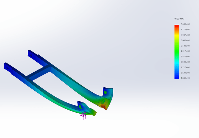
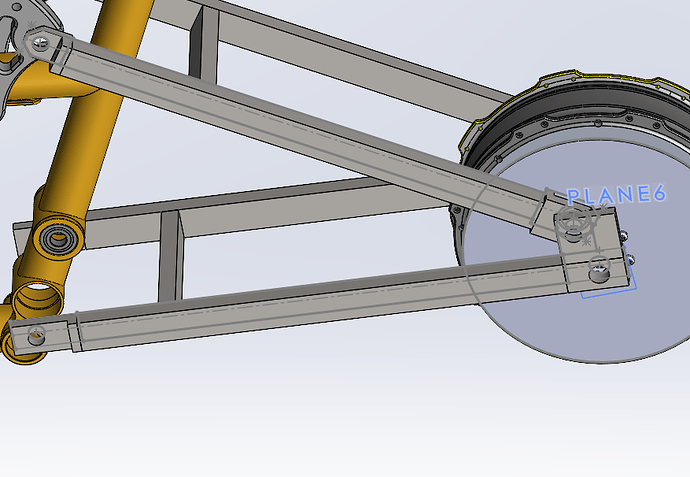
Here’s my design so far. Its not pretty but its going to be easy for me to fabricate and iterate on:


This is a 4-bar suspension design using rectangular tubes since its easier for me to weld and machine parts for and since I’ve done this on a motorcycle frame successfully. These are 1"x0.5"x0.089" carbon steel tubes - so hoping thats strong enough. All the joints are machined 8mm or thicker carbon steel pieces. I’m only building the swingarm right now - the suspension rocker / frame was built earlier.

FEA was done by using fixed geometry for the pivots and applying a vertically upwards force on the axle hole. I just need to know if this thing will break on a bottom out, so my thinking is that at bottom out the spring is not involved and the whole thing becomes one rigid swingarm. Let me know if that assumption is incorrect.

Thank you! Am new to this so any input is appreciated!
2 Likes

Stoked to see more full suspension questions here! Would love to see photos of the full bike - sounds like an interesting design.

The old swing arm, do you know exactly what material it was? If I had to guess, the failure was more likely due to fatigue stresses instead of pure ultimate strength. Although possible, fatigue stress is notoriously complex to simulate in FEA. Because of this, many larger brands have dedicated test labs to cycle test their designs in real life.
Knowing material, shapes, wall thickness, etc of the failed parts should help give a lower level baseline for the new robust design.

From the screen shot, I see some non-standard components acting on the suspension.
How much does that hub motor weigh? Since the motor is mounted to the end of the moving linkage, your sprung/unsprung mass ratio (and pivot forces accordingly) will be much different than ‘standard’ full suspension bike for trails.

Instead of ‘what is the max load’ question, a better question to ask is what suspension events are you expecting this vehicle to encounter? Are you planning for fully loaded dropping off a curb? Or sweet loading dock sends to flat? Each scenario will require different strengths in the design. A free body diagram would be helpful to start.

I’ve used this calculator in the past to run gut-check numbers for loading: Energy of falling object

“What displacement/stress tolerable” is dependent on exact material choice. This is a much broader engineering question - I would suggest researching material mechanics, material data sheets, and beam bending problems. Here’s a good starting point to dive into: Mechanics of Materials - Engineer4Free: The #1 Source for Free Engineering Tutorials

The FEA simulation does not look representative of the real system and will give an incorrect result. Here’s an excellent write up of the mechanics of FEA and how we can approach it in framebuilding: FEA for Framebuilding

Specifically, there should be an axle of fixed length preventing the swingarm from caving in. Hubs are a significant strength member in the overall system.
A distance or slip constraint should be enough. You could also model in a dummy axle and leave it rigid.

For fixed geometry, I would only fix the main pivot location, not the Horst. The Horst pivot will have a reaction force in the linkage that is dependent on your wheel load at bottom out. Linkage Pro software can calculate this, but this is also where the free body diagram of the whole system is helpful.

FEA is not a be-all-end-all and is only as accurate as your constraint system is to real life.

Hope this helps!

2 Likes

Thanks for the interest!

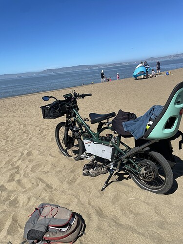
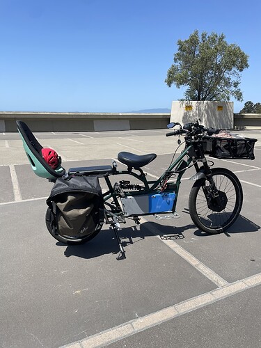
Here’s the bike:


Full suspension, dual motor, big battery and no pedals. No pedals allow the seat to be significantly lower and frees up the frame space for a giant battery. Legally not a bicycle but a electric scooter in California. I realized after years of owning a cargo bike that I was mostly pedaling for optics anyways. Going up 10% grade on a 80lb bike with 100lb of cargo means the motor is basically doing 95% of the pulling :joy:

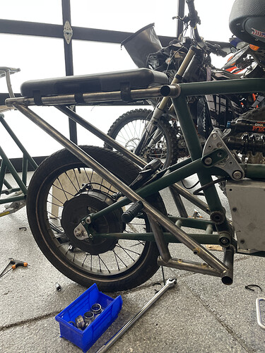
This frame was done by some amazing students out of CalPoly. I’ve since then been iterating on the design myself. Swapped out the rear subframe for something lighter and with mounts for a swing out wide stand and with foot pegs since kids demanded it:

I’m actually working on a v2 with 20" tires front/back and slightly beefier front forks (possibly a motorcycle front fork), making the frame a bit more rigid and having smarter features (electronically locking brakes, traction control, turn signals etc) - mostly safety features I think such bikes should have when carrying kids in urban areas.

Regarding your earlier questions:

  • The chainstay was a 12mm x 1mm wall butted 4130 tubes from bikefab. The tubes themselves didn’t shatter but sheared around the weld.
  • Definitely a hub motor. Great idea to model that as well - will add a dummy axle!
  • Definitely dropping off 6-10inch curbs. Potholes in the SF Bay area can be just as deep :smile:.
  • Falling vertically is one scenario which I feel is easier to model but I also want to figure out the force of hitting a sharp vertical climb right after a pothole (which broke the last swingarm). Any idea how this could be done or what the thought process would be? Is this something that MTB folks do?
  • I totally agree my question is super vague - was more looking for back of the hand rules for stress given chromoly 4130.

Good point on not fixing the horst link. I have changed both to ‘hinges’ in solidworks to allow rotation. Are you suggesting model it as a 2D dynamic system instead of static? My assumption was that instead of getting into suspension dynamics (which is complex) can’t I just try running FEA at bottom out? This way I should be able to model the chainstay + link/clevis as rigid and all I need to figure out is the force on the axle? I’m trying to not spend TOO much time with FEA since like you said - its not a be-all-end-all. I’m just trying to make sure my basic assumptions about tube and machined part design/thickness are correct.

Thanks for the links! The writeup by luniz82 looks super informative. Will check it out.

2 Likes

I seem to remember walt recommending using fork blades for chainstays on tandem bikes/heavy loads. Would probably be a bit beefier than a standard chainstay. Good luck with the repairs!

1 Like