Yes indeed. I definitely could use the practice. But so far I have spent all my (limited) time for this hobby planning, and not actually building, my first frame, so I am hoping to cut a few corners so I can get to the tools sooner! ![]()
Paragon had STEP files for most of their dropouts. Can you use their dropout as a proxy (or just order their dropout)?
I’ve also played with modeling a parametric frame in Fusion and just didn’t model the dropouts. That is a detail that I can figure out at build time.
3 Likes
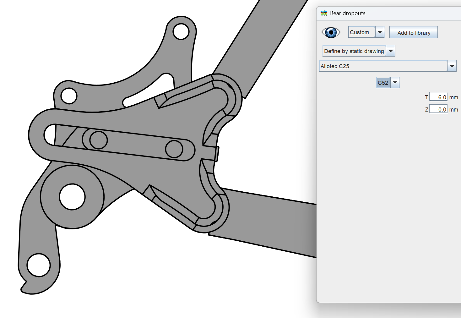
Does BIKECAD has this dropout?
Good call.
When I first checked, I couldn’t find it, but then I realised that C52 is the insert, not the dropout.
So BikeCAD does indeed have it.
Pick Allotec C25 plus C52 in the insert selector.
2 Likes
Good point. I think in the end I am just going to print what I have and muddle my way through the dropouts as I get there. Thanks!
Miter bevel question here:
I have a tube that was mitered to match another one, creating a miter and the related bevel.
The laser cutting service I am using has a bug on their software and when they detect a bevel that is less than 45 degrees they replace the whole cut with a bevel of 90 degrees (no bevel at all).
This means that if my miter bevel goes from 70 to 30 degrees along it’s path, it’s turned into a straight 90 degree cut instead.
Now, long story short, I talked to their support and they do acknowledge that their conversion software has a bug, however, they don’t think it’s fixable so:
Is there a way I can modify the bevel of a miter cut afterwards?
I am thinking that if I modify to stay within their limits, I may have less material to file away (as it seems that I am 1 degree over the limit!!)
Looking for post processing, scripts on STEP etc or clever solutions via F360
Several months later, so it might not be useful anymore, but I just figured out how to get the STEP files via BikeCAD and FreeCAD.
ALLOTEC_C25.step (799.2 KB)
ALLOTEC_C52R.step (1.3 MB)
ALLOTEC_C52L.step (1.9 MB)
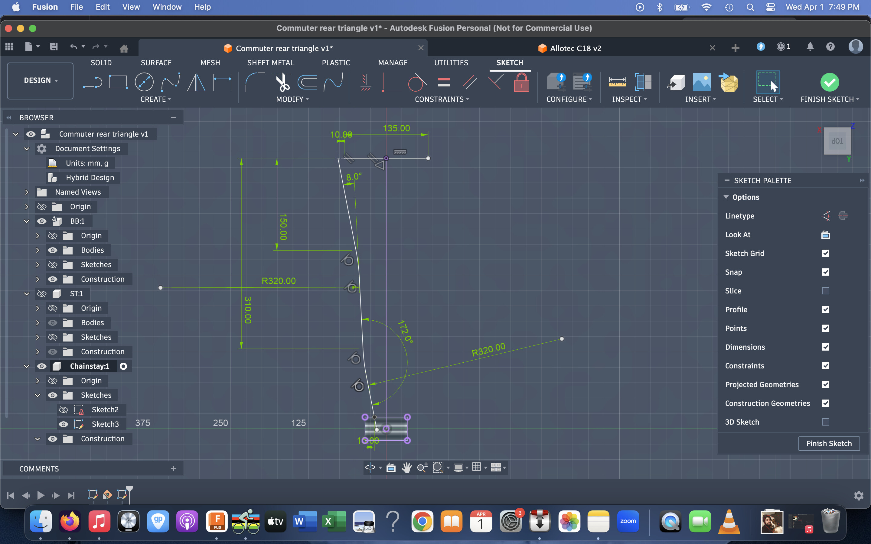
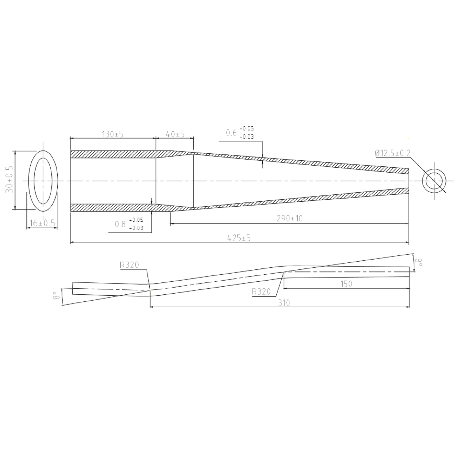
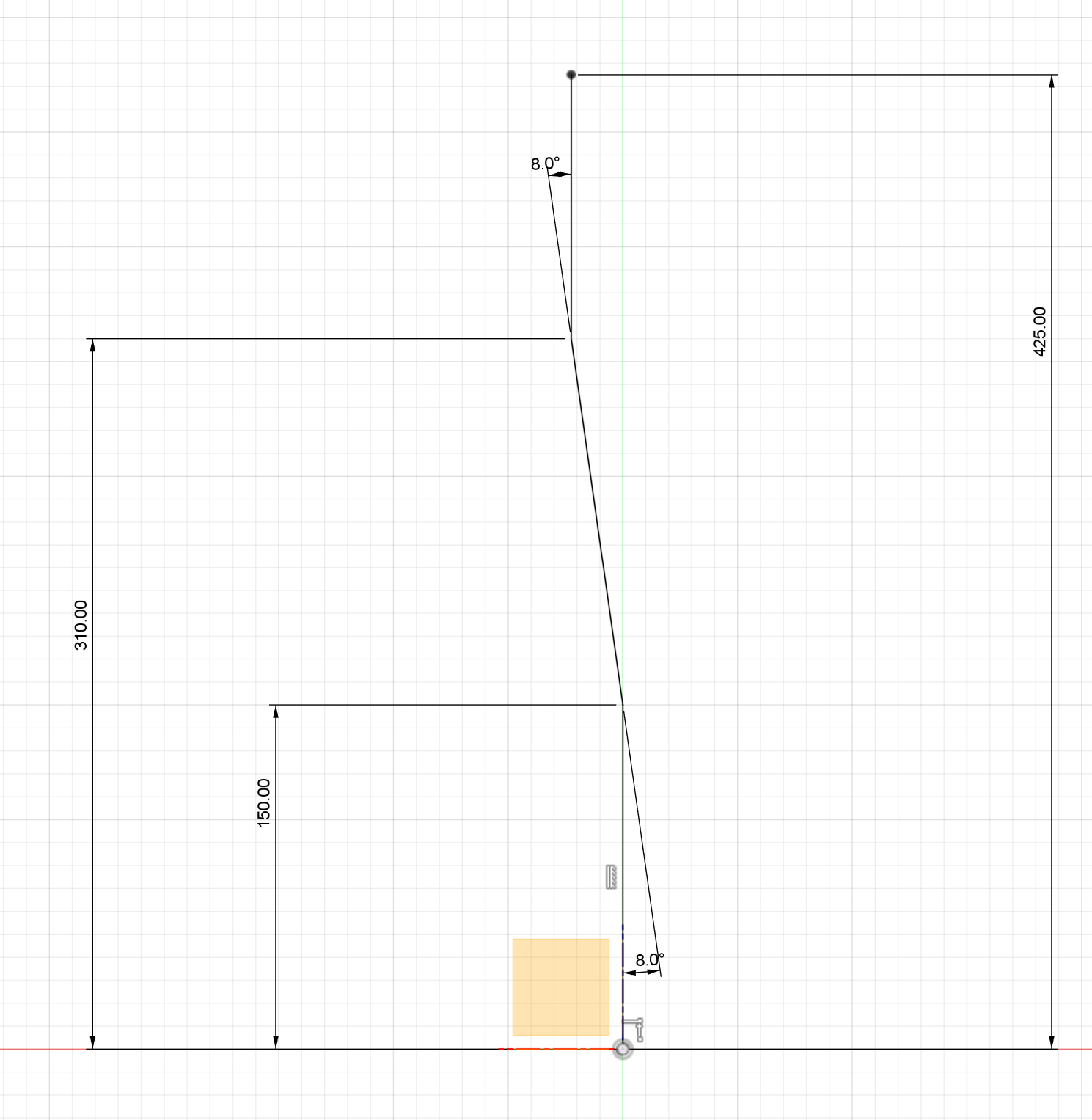
I’m trying to model the chainstay below to check for clearance, but I’m not sure what’s the easiest way to input the distance from tip to first and second bend? Right now I dimensioned them from tip to beginning of bend, which I know is wrong, but I can’t figure how to find the center of the bend
Here’s how I dimension these:
It looks like from the supplier drawing that the 150mm measure is horizontal. From there, the 8deg are measured from the center section.
It appears all of the linear dimensions are marked to the center of each bend, so you can ignore the tube radii until you’re ready to sweep the profile along this simplified path.
1 Like
Right that does make more sense. I never used the sketch fillet tool before so I didn’t think of using it to add the radii to existing sketch line, I tried it and it work perfectly. Thanks for the tip!
2 Likes
Incredible! Thank you!
Finally my slow pace on this project pays off….
1 Like
Hi everyone! First of all, I’ve been following this forum for a few weeks and have learned a lot — thank you!
I’m pretty new to surface modeling, and one of the things I struggle with most is visible transitions between smooth surfaces (see pic 3).
I’m currently following @colinreay approach from the Designing elegant 3D-printed dropouts in fusion360 - #12 by colinreay
Here is an example I’m working on right now:
What I did was extrude my sketch silhouette (pic 1). Then I have created two additional shapes (pic 6) to have more control over the form. I used the Patch tool to create smooth shapes between edges of the ‘tool’ extrusions.
The issue is that, with this approach, the tangency doesn’t work as I would expect it to for the two additional edges. (see pics 4 and 5 — edge #2).
I’m glad you posted your solution. Because it’s exactly what I was going to recommend. That part is looking nice.