Ask questions, get answers
I’ve been picking away at designing a chain stay yoke with fusion360. I’ve created a 2d sketch with clearance dimensions along with the profile for the yoke itself. I was able to accomplish this from following along with @Daniel_Y fusion mtb tutorial. I learned from @swood how to utilize the sweep command with a path/guide rail to create a 3d shape from the 2d sketch.
I am now at a stage where I want to add some sort of internal structure to the yoke and would also like to further manipulate the 3d form (ie. create clearance for the seat tube/thin out the bridge between the L/R yoke plugs and aesthetics). I am well beyond where I would have got on my own and would like to further lean on folks for more direction. Ultimately, I want to get a yoke printed, and I’m sure to not be alone in this desire. My hope is to have a general outline for folks to follow while picking their way through the process.
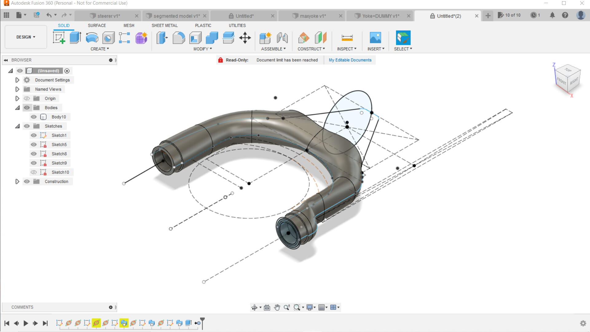
Here are my sketches and where the 3d form sits currently. I have no clue on where to go from this point. Thoughts, directions, criticism welcome
2 Likes
This is a great first try, and pretty much the same workflow I use.
A few tips:
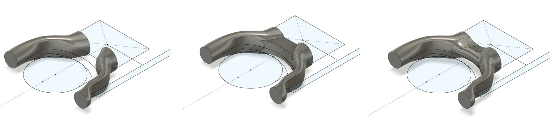
I start with two legs, then join them together with a simple extruded bridge and some liberal use of fillets:
I get by with the tools that I have, but this is actually beyond my scope of understanding. Making something look fancy is part of industrial design, where they will generally use surface modeling techniques rather than parametric design (driven by geometry equations) that engineers use. Surface modeling is on the list of things I need to learn.
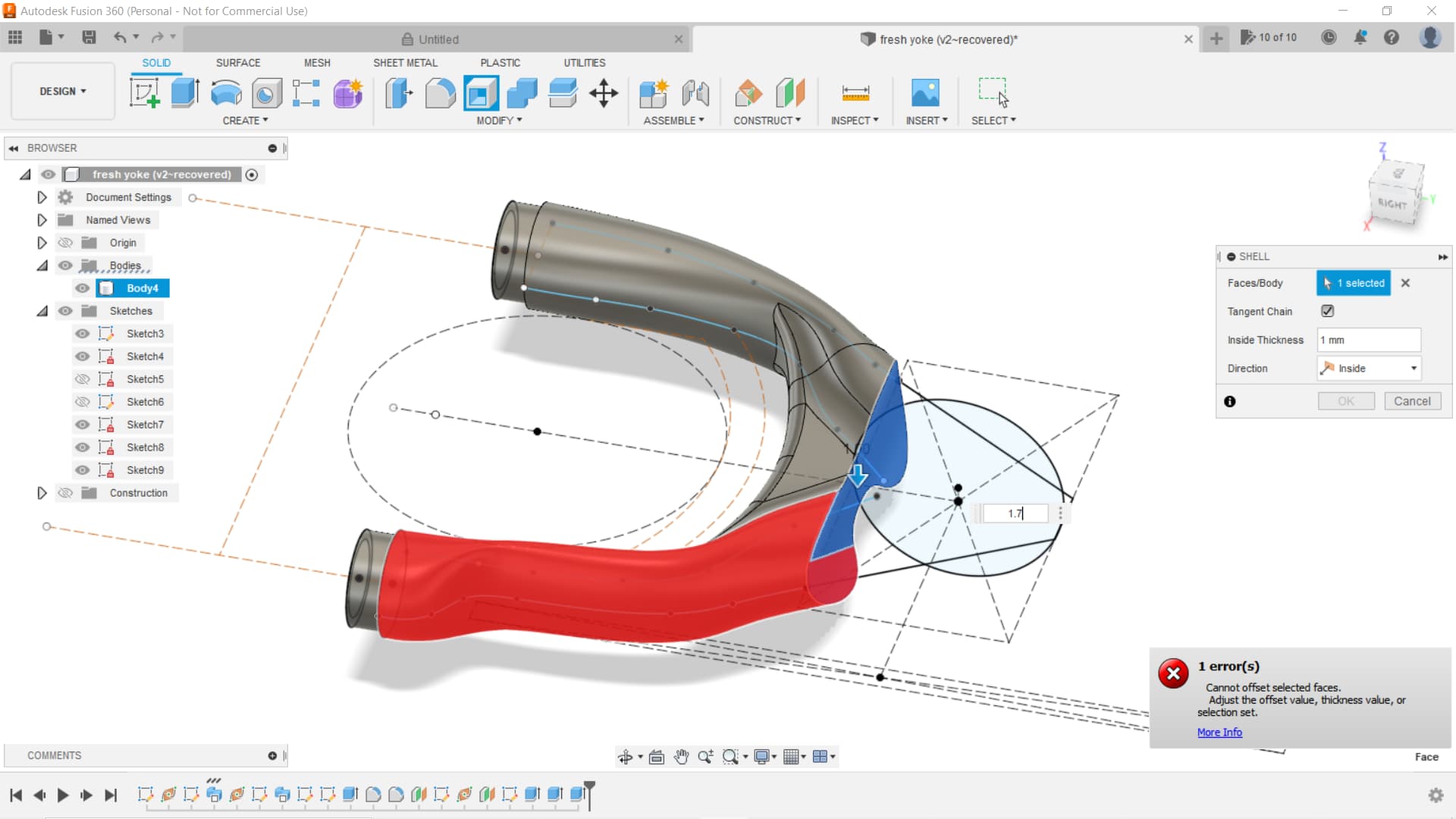
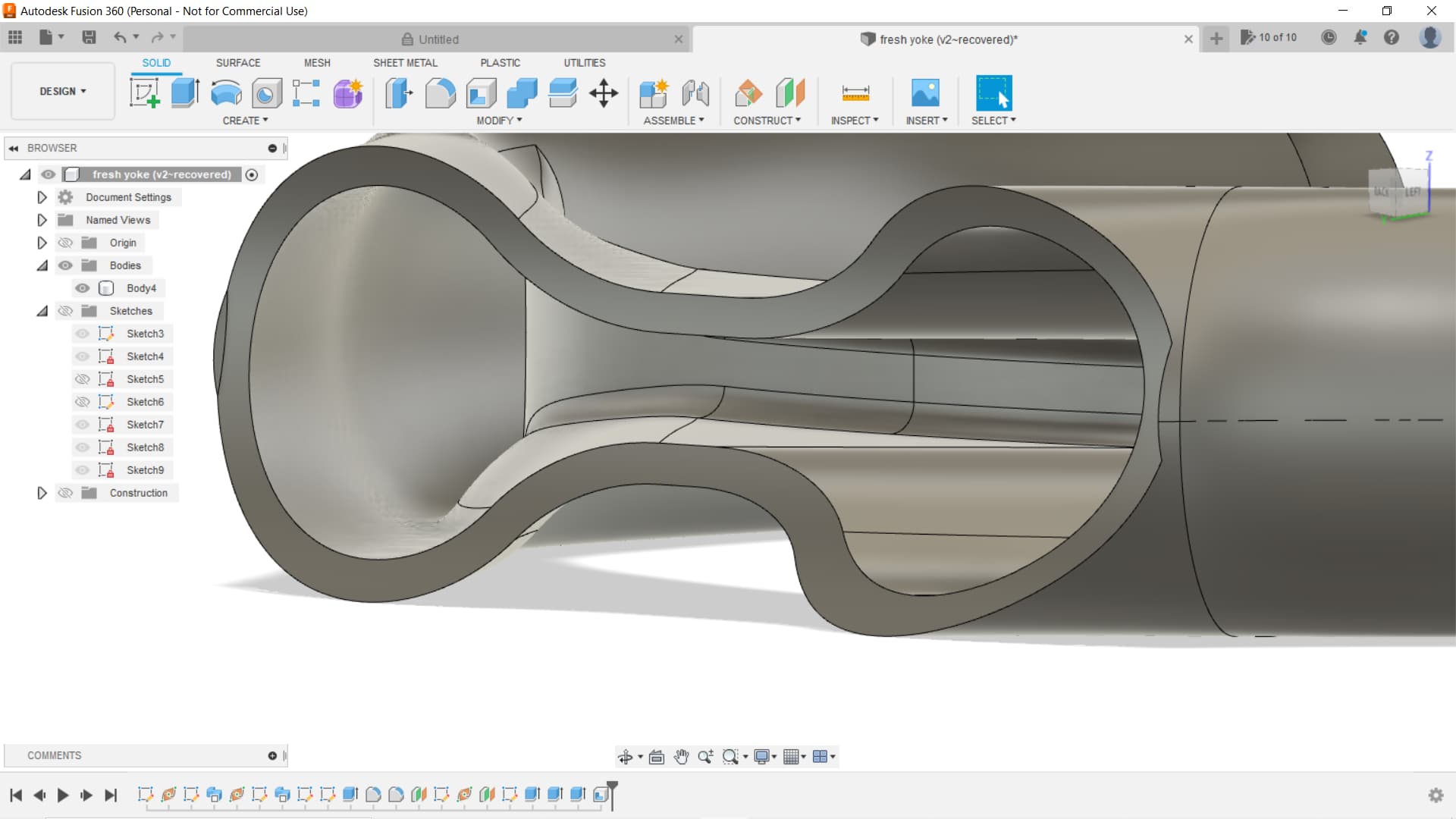
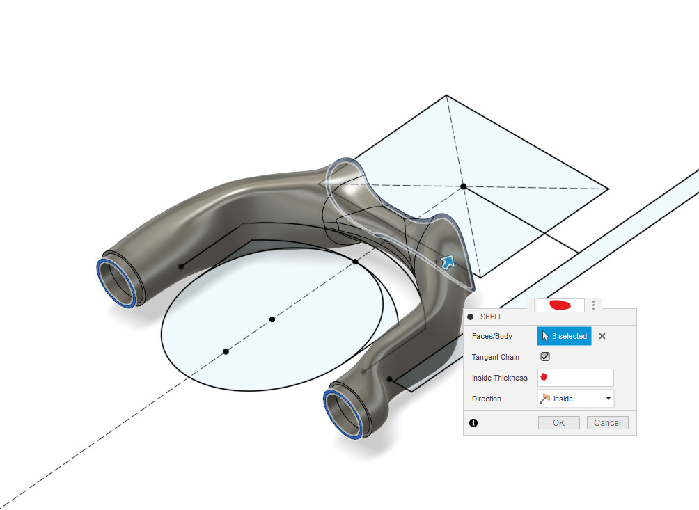
I suggest you use the shell tool instead of sweeping a tube. (I redacted the wall thickness to give the opportunity to think critically ![]()
Another recommendation: add the nubs at the very last step as a simple extrude. Don’t include them in your rail sketch.

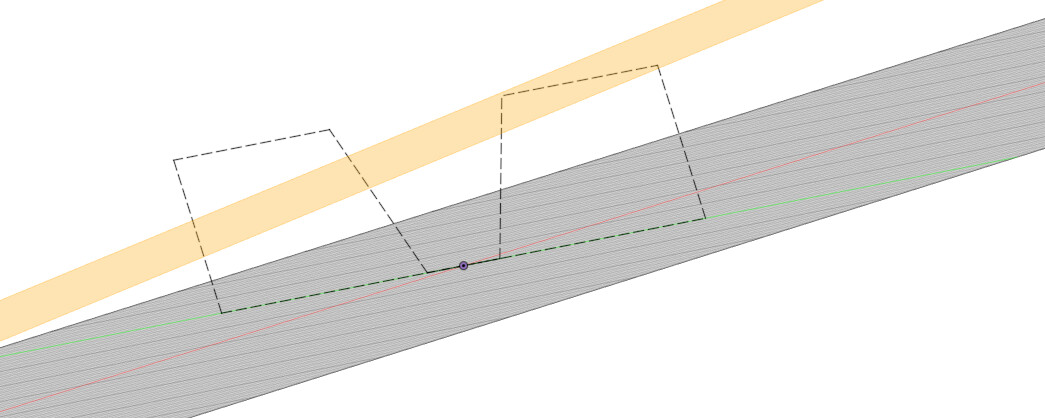
I think you need more clearance here:
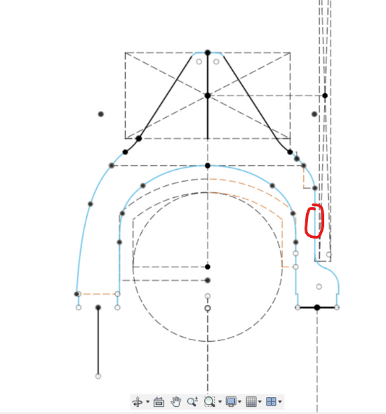
Shimano cranks have a rivet at that location that will rub. You have to be 3mm away from the chainring box to clear that rivet.
![]() opinion alert: I don’t think the internal structures people manually generate in yokes are doing anything except creating stress risers and increasing the chance of a print defect.
opinion alert: I don’t think the internal structures people manually generate in yokes are doing anything except creating stress risers and increasing the chance of a print defect.
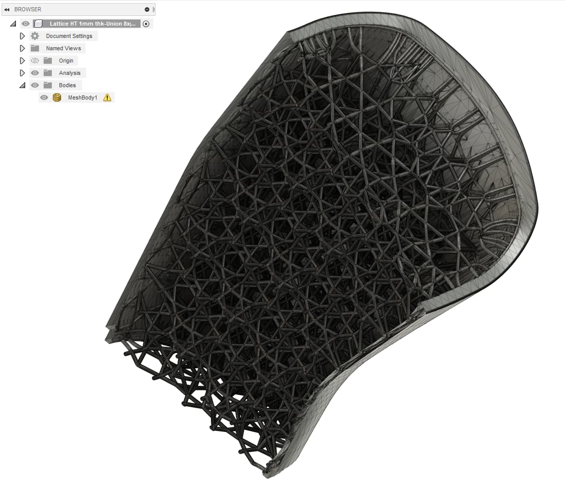
To do lattices properly you need two things:
- a $20k/yr license of nTopology
- nTop used to give out 30day licenses if you want to try
- people also use Grasshopper plugins, but I think that workflow is less common
- A printing fab to agree to print your lattice
- printing fabs need to be careful what they print. If one of the lattice’s wires pops up, it can ruin the entire print
OR, you can pay a printing fab with nTop an engineering fee to generate your lattice and print it for you.
Bigger picture, I think people need to step back and ask what is the purpose of the lattice in the yoke That is one of the dangers of 3D printing: You can get carried away with the power ![]()
The good news is, if you want an internal lattice, you need a good model of a yoke to start, and you are 80% there
2 Likes
Do you have any opinions on the new(ish) “Volumetric Lattice” feature in the Product Design extension for Fusion? I haven’t messed with it yet, but you can use Autodesk extensions pay-as-you-go.
1 Like
Wow, that is news to me! Great call out! I’ll look into it.
Being able to lattice things in the CAD program has been a big missing piece in the additive workflow. At the moment, you had to jump through several hoops:
- 3D CAD > Export STEP > Import to Ntop > Lattice > combine
If you changed your CAD you have to go through that process again.
Hello Sharks,
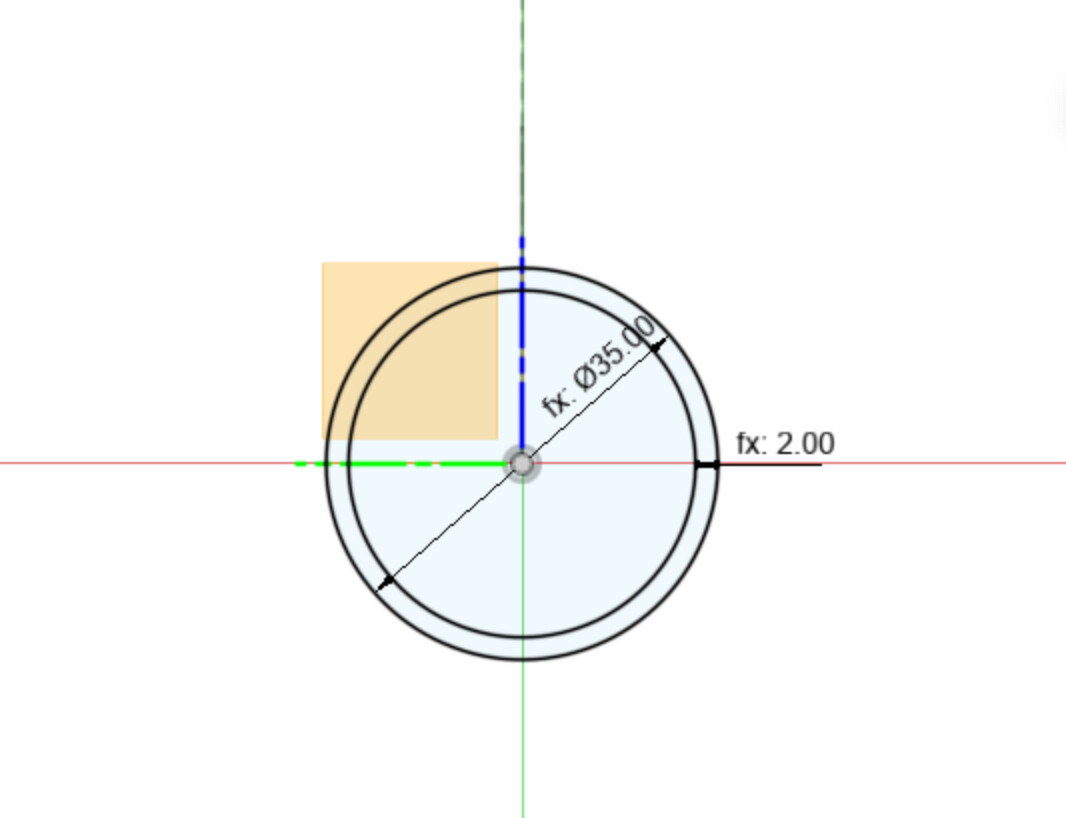
Today I am looking for advice on how to quickly get a .dxf file from an somewhat involved sketch, for a 0% stake in wzrd. bikes.
Projecting into a new sketch seems to work, but is slow when you there are so many silly little lines - especially when the lines are stacked. Is there a way to easily export a highlighted face into a send cut send friendly file type?
Thank you for your time and consideration.
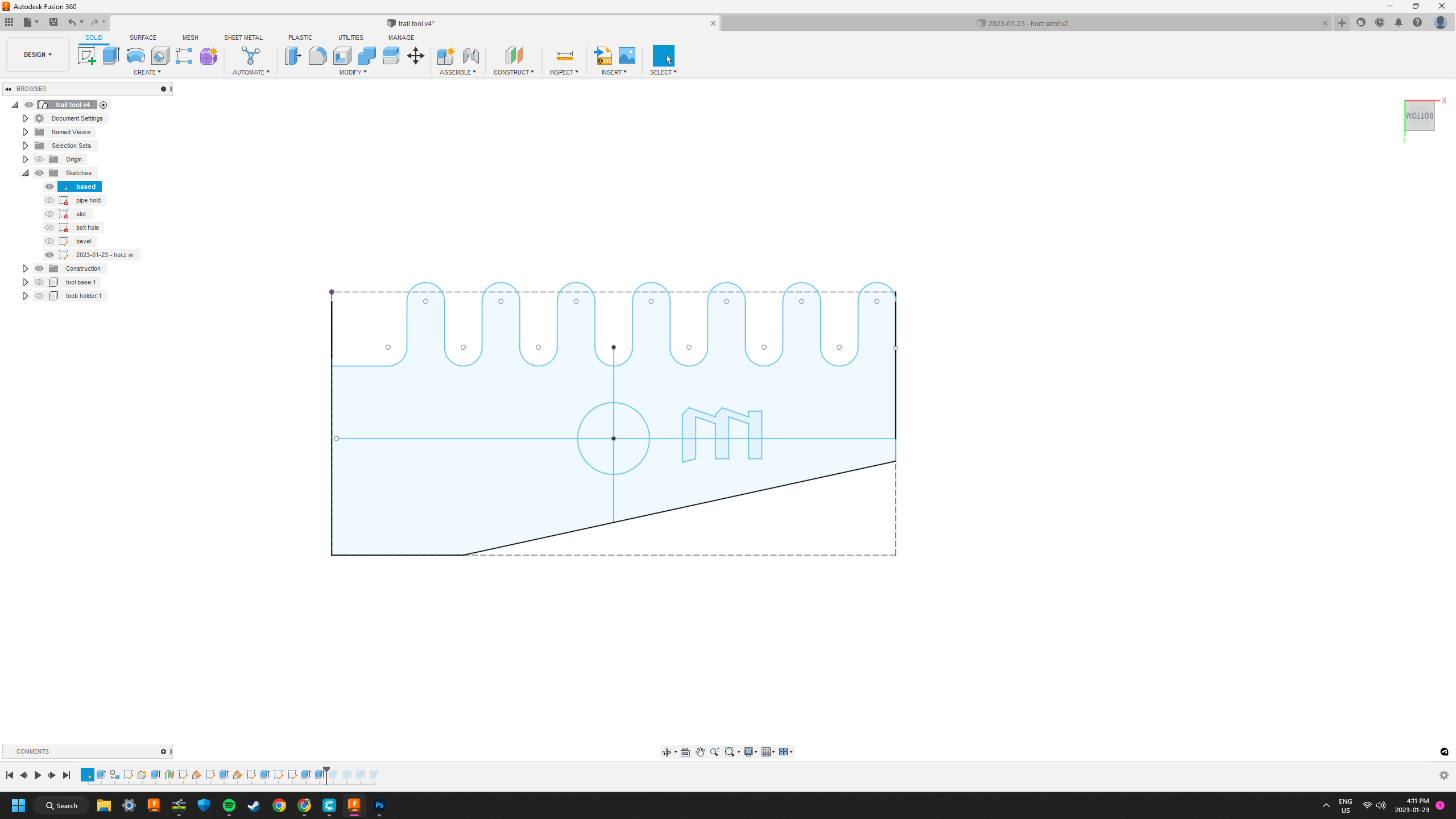

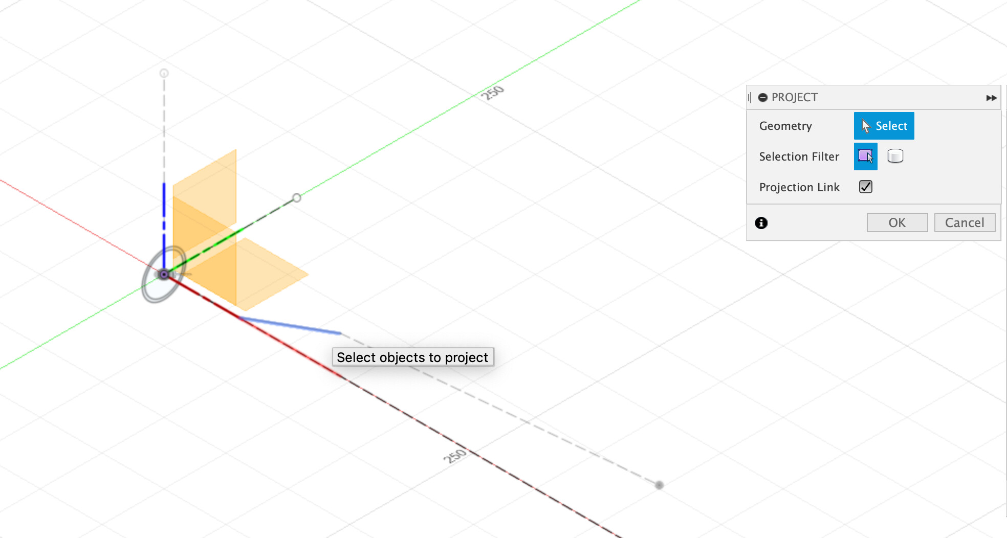
I think this “Exporting to DXF” covers it

If you select the entire face and project it, it will grab all your features automatically. I haven’t come across a geometry that breaks it, but I’m sure there will be.
2 Likes
The one video I didn’t watch! Thanks.
1 Like

1 Like
@maxwellkeegan @Daniel_Y Industrial designer here to talk about surface modeling and editing 3d forms!
Good surface modeling should be somewhat parametric, and often combines a lot of solids and surfaces in the model tree. If I were approaching this part, I’d build it in many smaller sections using the loft tool more than the sweep tool. A master sketch typically drives each sketch, and editing dimensions in the master will automatically update the affected surfaces.
There are pretty powerful surfacing tools in Fusion, and I’d be happy to take a shot at specific questions!
3 Likes
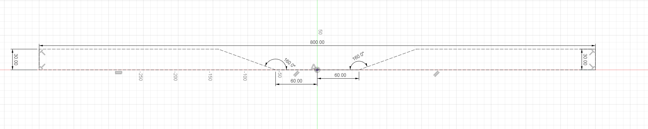
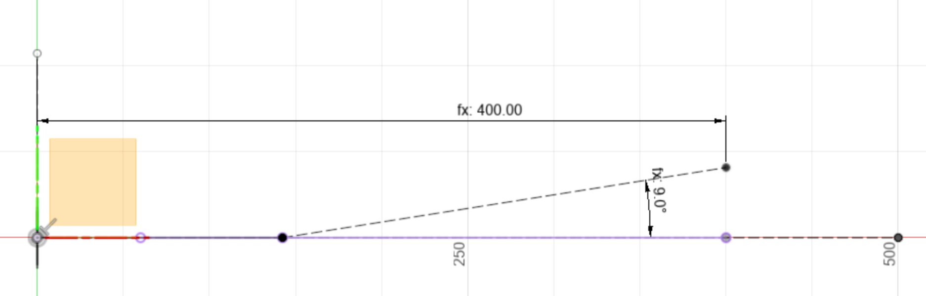
I’ve been playing with modeling some handlebars(800mm width, 30mm rise, 9* back, 5* up), looking for some critique on my approach. I’m also unsure if i’m correctly drawing the up-sweep (if that’s a real thing… PVD).
I started with a 2d sketch of the front profile of the bars, which would define overall width, rise and bend positions.
Then I created an offset construction plane at the rise height, and draw another 2d sketch on it representing the back sweep, with the tops of the bends projected from the first sketch.
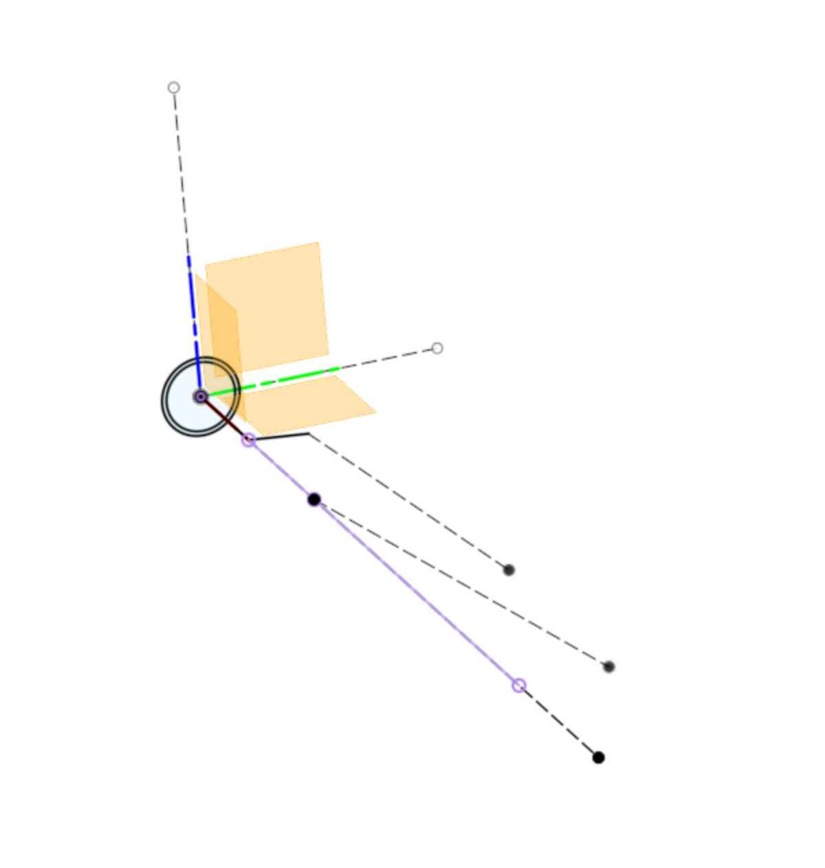
Next a construction plane at an angle around the front profile of the bar.
And another 2d sketch on it connecting the top of the bends(projected) to the tip of the back sweep(projected).
And finally a 3d sketch representing the bar centerline, connecting the lower bends, the upper bends, and the tip of the up sweep. And we wind up with this…

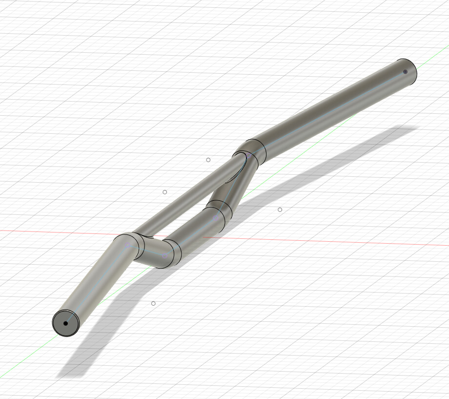
Does this seem right? Am I representing the upsweep in the correct plane? Easier way to do this?
Thanks!
Hey @Swood! I’m a huge fan of your work!
I’m gonna take a shot at rebuilding these bars with the dimensions you gave. I think I can offer a few tips to make it easier/faster/more robust.
Step 1:
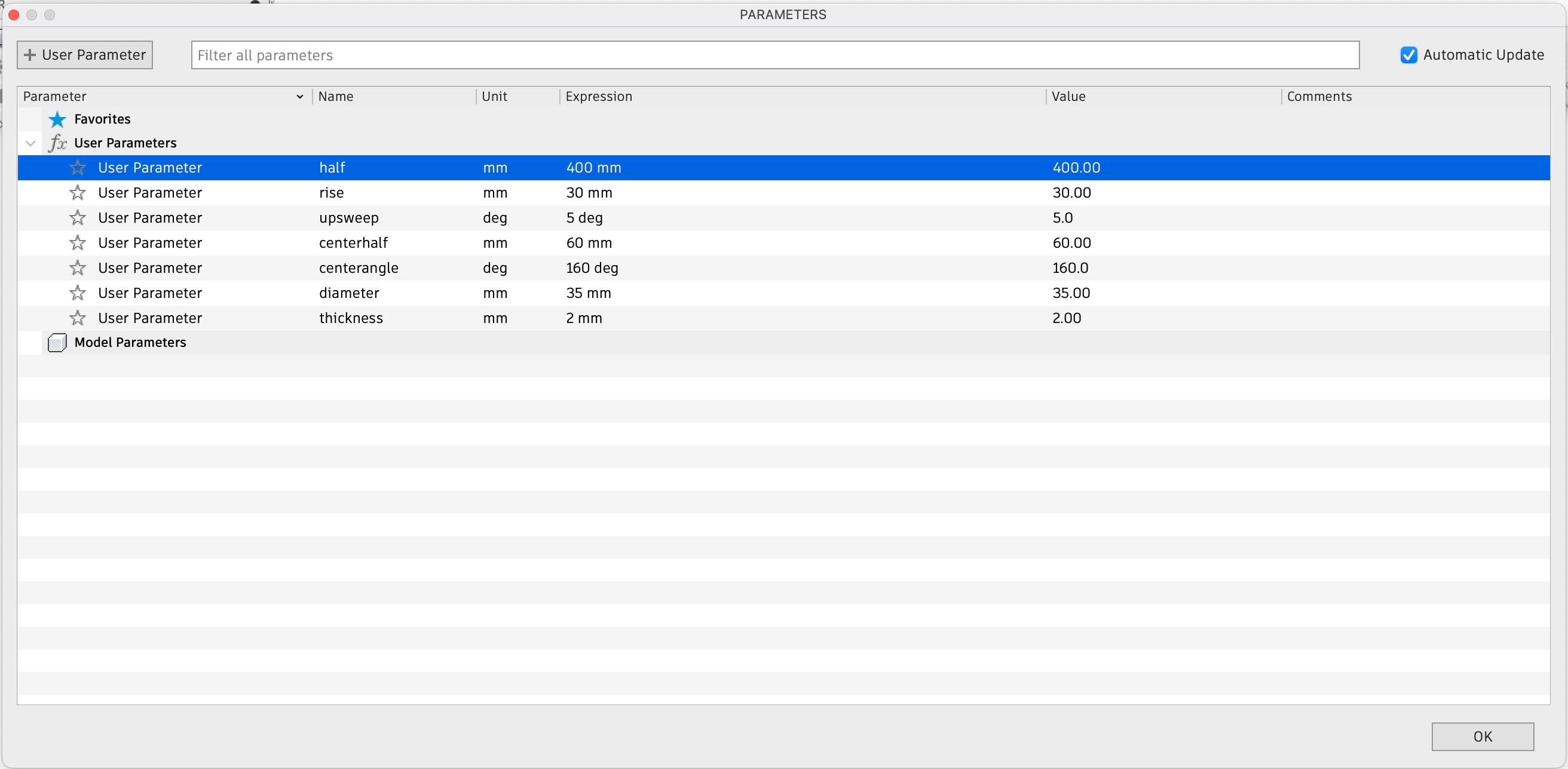
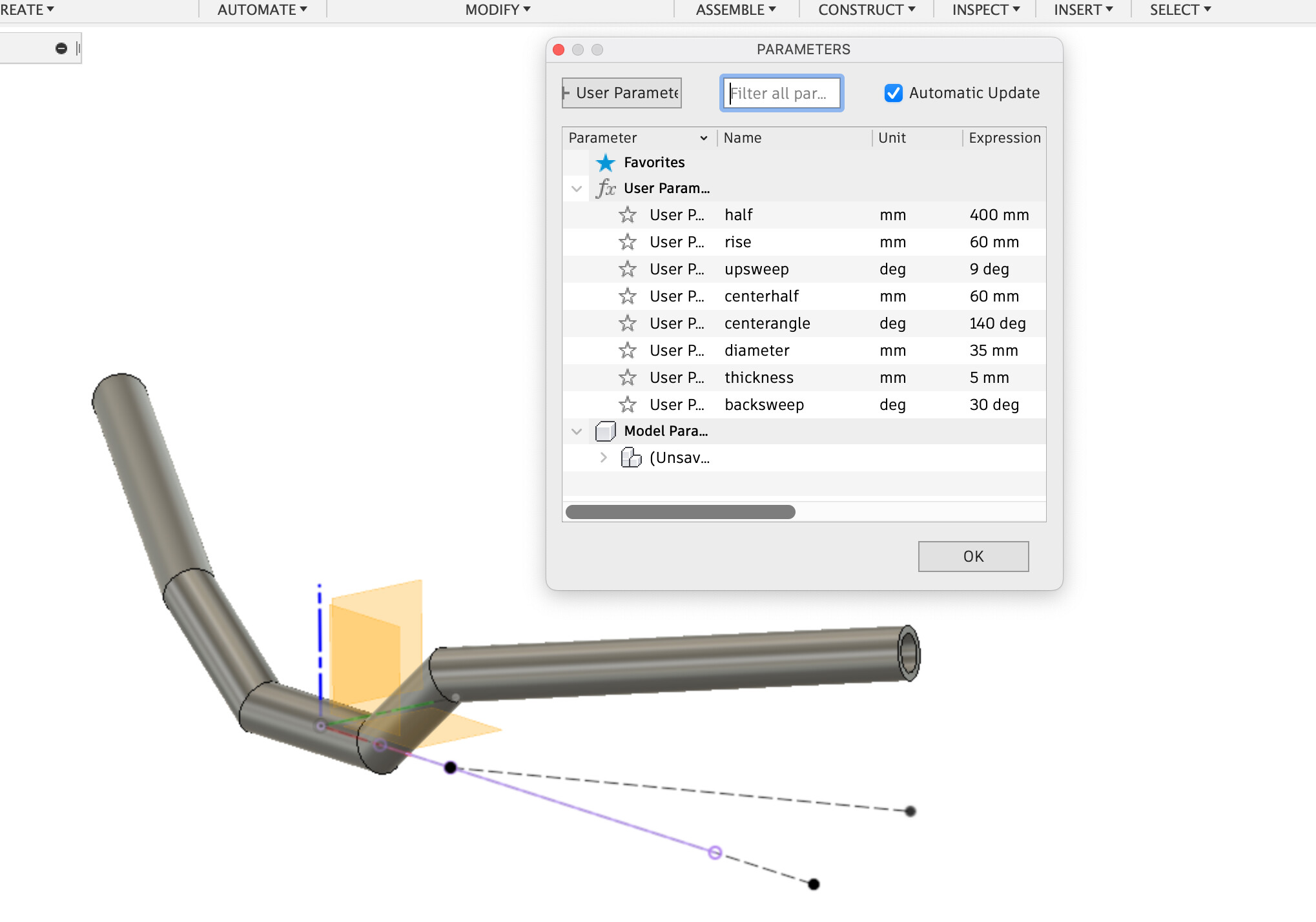
Functions: We know all the dimensions for this set of bars, so we may as well put all those values into the software at the beginning. In the future, we can then just change those values, and the model will rebuild itself for us. This is done in the Modify → Change Parameters tab:
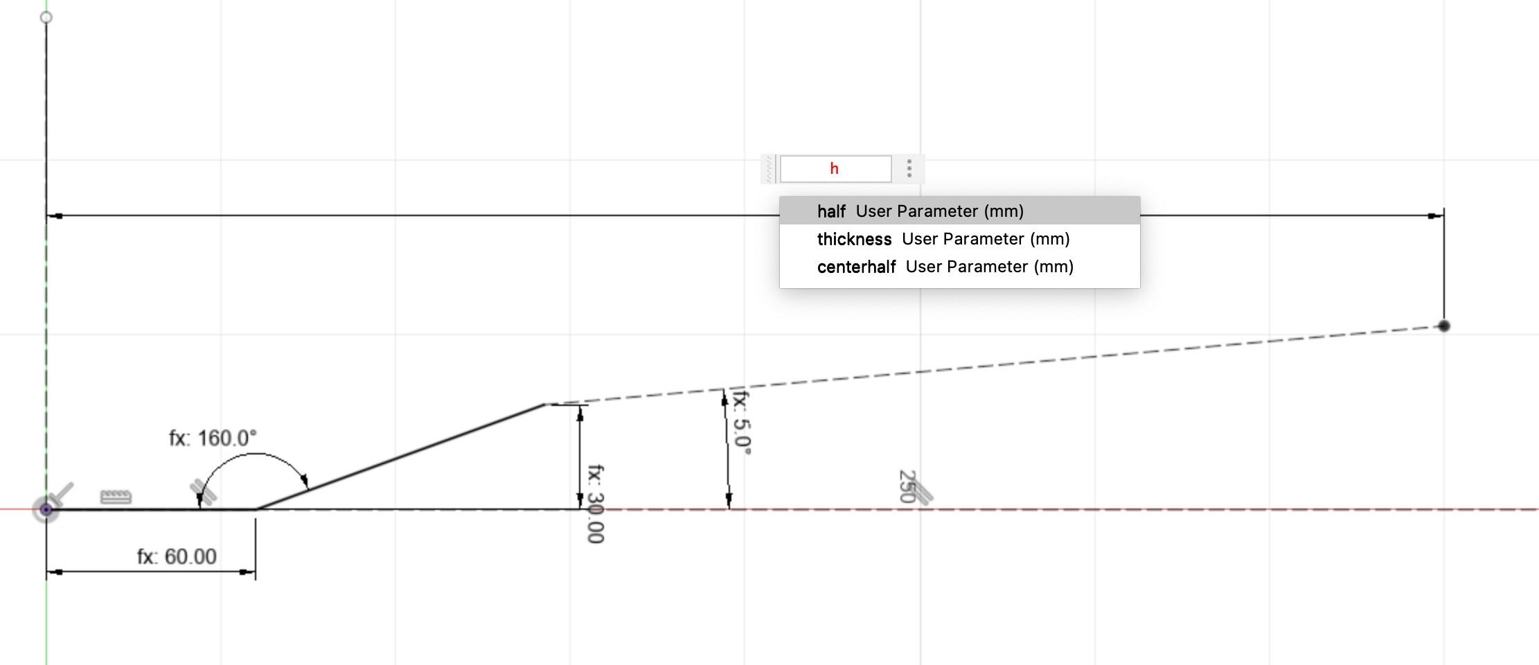
Next, I’ll do the front plane sketch. Start with horizontal and vertically constrained construction lines. Rather than typing in the dimensions of everything, I’ll type in the name of the parameter that we came up with earlier. Note that I’m only making half the bars, and what part of the bar I have drawn is not horizontal, but has the upsweep parameter applied. I’ve also made this section a construction line.
Next, I’ll do a sketch on the right plane to make the tube profile centered on the origin. Same deal with the functions rather than dimensions:
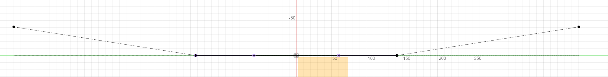
Now the fun part. Make a sketch on the top plane, and draw in your vertical and horizontal construction lines. Then, we’ll project this line down from the front plane to the top plane:
Back in the top view, we’ll draw in our “backsweep” line, with the end terminating at the rightmost pink point from our projection. Then add in the dimensions. Everything in this sketch can be construction lines.
We should be left with something like this:
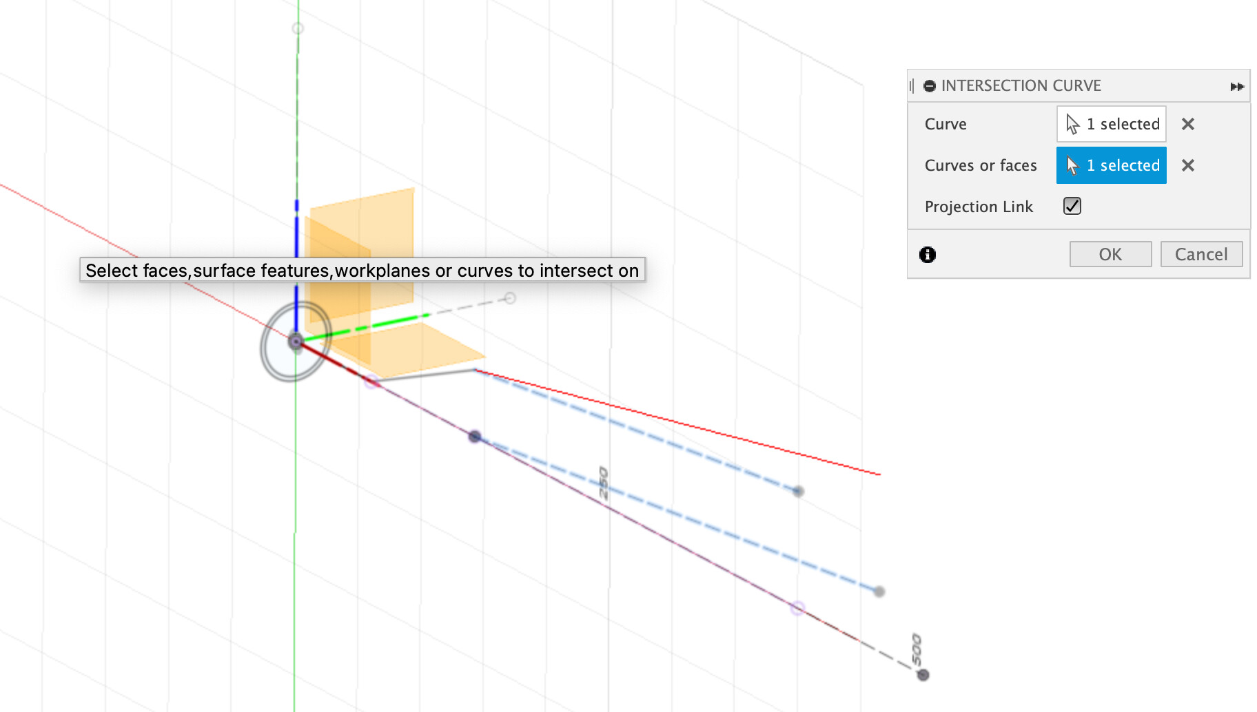
If that all looks right, we can do the projected curve. Start a new sketch, and go to Create> Project/Include> Intersection Curve. Select both of the angled construction lines from earlier, and you’ll see a red preview curve show up. Command basically projects each towards each other as a plane. The intersection of the two virtual planes becomes your new line- so we just captured both the upsweep and the backsweep. (Sorry PVD)
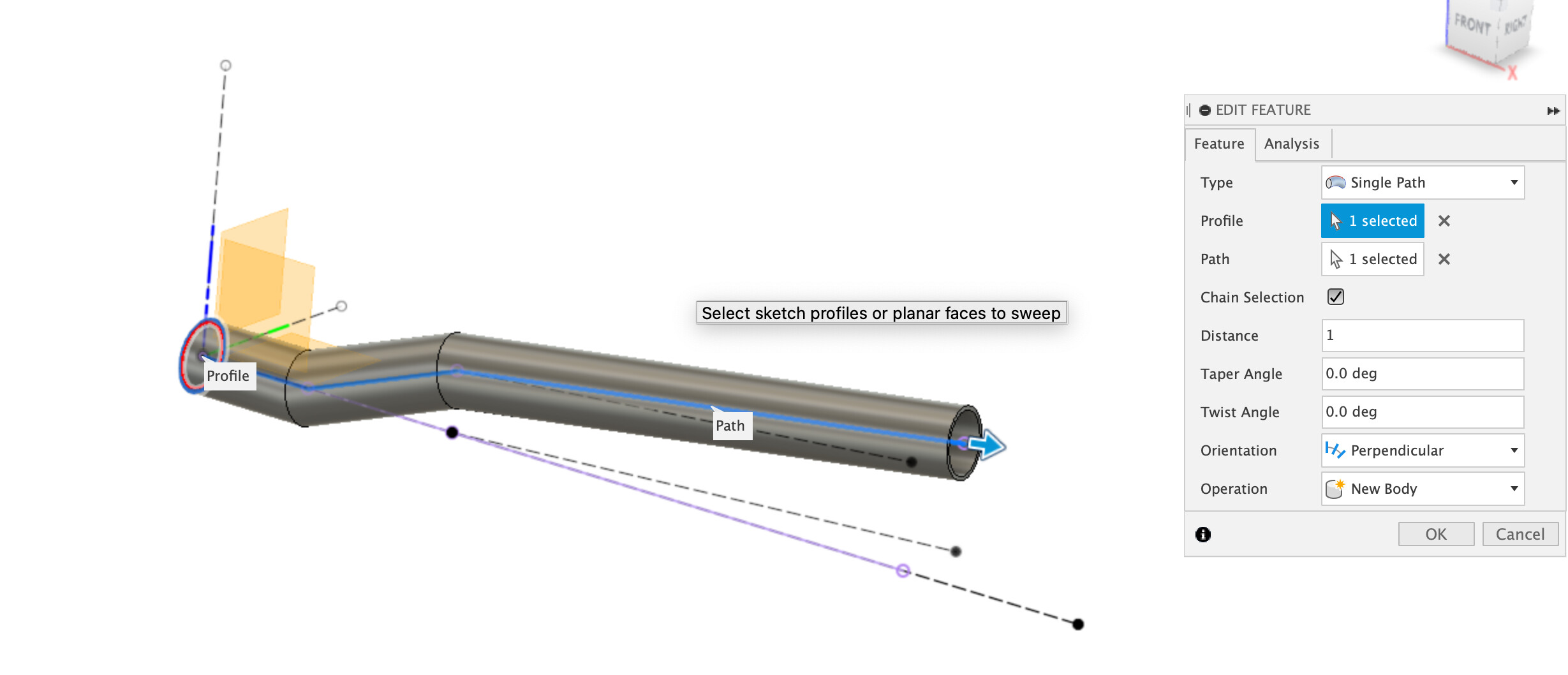
Finally, we can sweep our profile along all of the lines that aren’t construction lines.
Then we can add fillets and a joined Mirror to clean things up.

My apologies for making this so long- that wasn’t my intention going in. Hopefully, some others who are less experienced can find this modeling workflow useful. There’s a lot of stuff in here that I wish I was taught in school.
Projecting curves is super useful when you want to avoid building a lot of extraneous planes and weird angles. Using Fusion’s functions for modeling is insanely powerful. I’d highly encourage using this process in your modeling, especially when you think you’ll be making edits in the future. It’s really slept on but can save so much time and ensure accuracy through changes.
8 Likes
Thanks for the detailed instructions @nickhiti1! That basically covers my workflow as well
This is my handlebar CAD, feel free to download and reverse engineer the feature tree: Fusion

@Swood a quick tip, its good practice to use the symmetry constraint or mirroring when design intent is to be symmetric

1 Like
Glad to know I’m thinking like a genius lol
1 Like
A quick little thing I do to keep myself sane: you can group things together in the timeline on fusion.
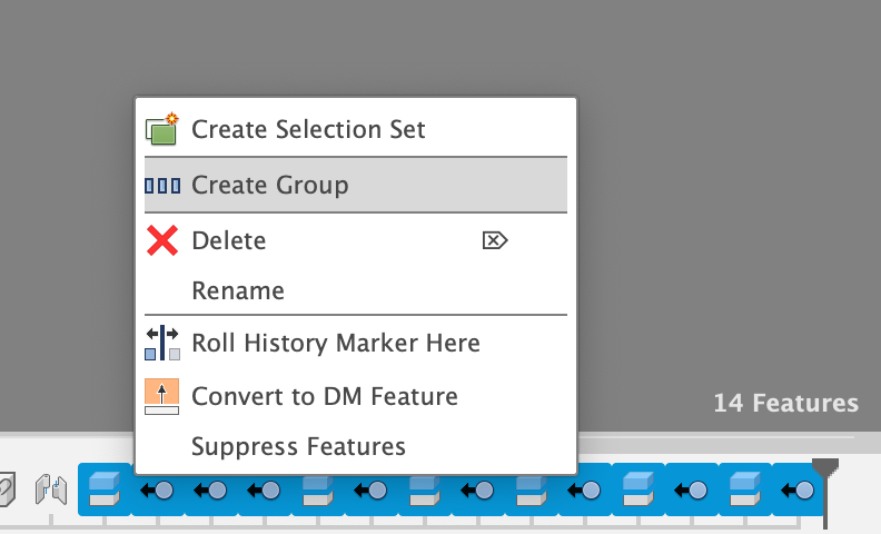
I tend to put all the operations for each part of the frame into their own group, and then I can go back and open those groups later when I need to make edits. Otherwise that timeline gets really long really fast, and it stresses me out. I hope that can help someone else out too!
11 Likes
YOU CAN DO WHAT?!? Such a good tip, thank you!!

2 Likes
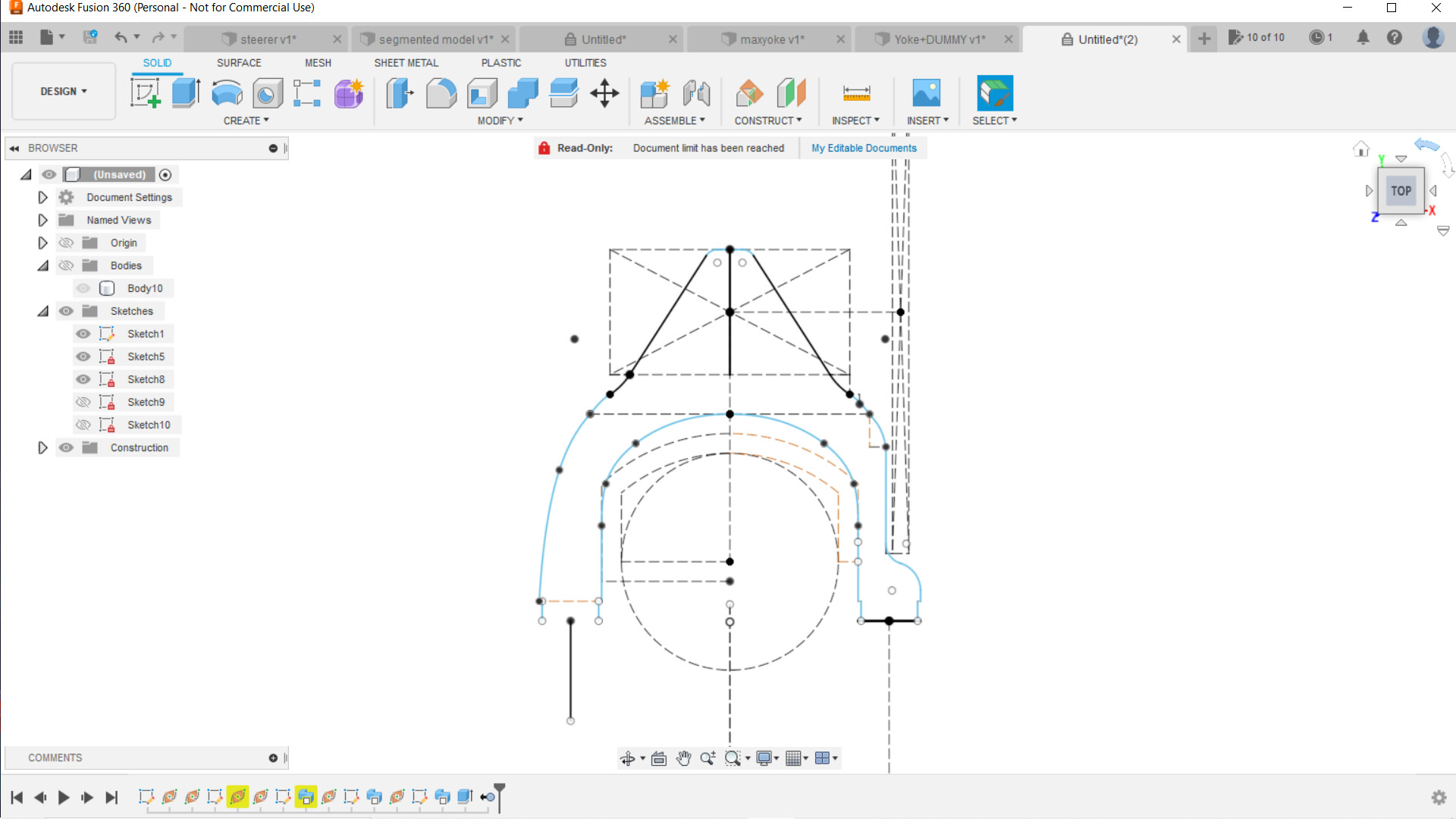
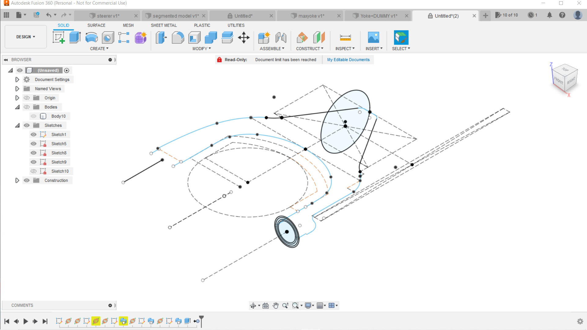
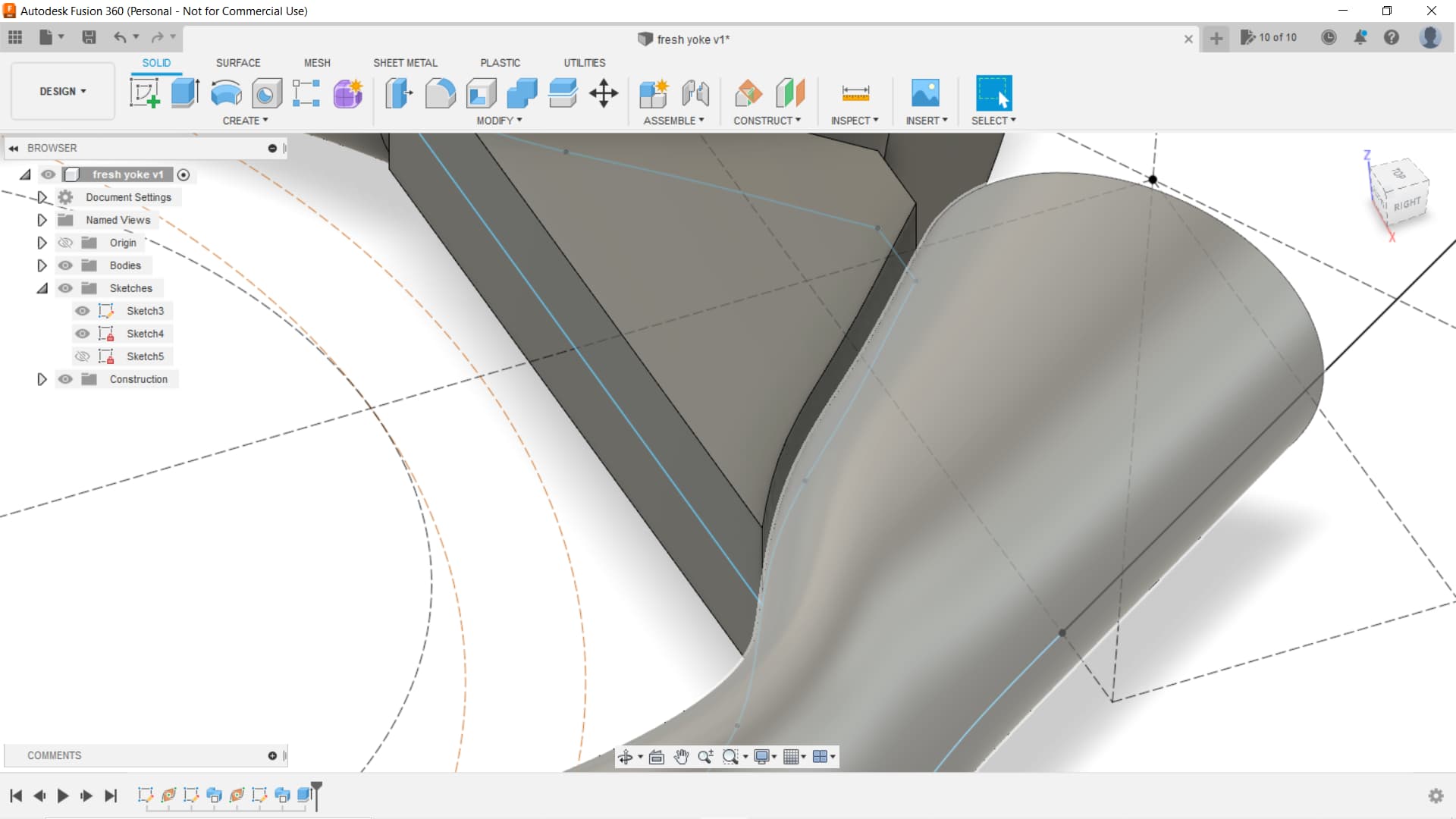
Started fresh, used the fit point spline tool to create my path and guide rail lines. I believe this gives the sweep a smoother path. Sketching the bridge between the two “legs” I cannot figure out how to join the bridge to the legs and maintain a line from which I can create fillets. I’ve tried press/pull but this joins the two and leaves no option for a fillet. When I try to extrude the bridge face to the leg body it won’t let me. Messed about with this for the last couple of evenings and have now resigned to asking for help.
@nickhiti1 I’d be interested to see the workflow using the loft command. I watched a few videos on the loft feature and can imagine how much one would be able to manipulate the form. I think this would entail creating a few different planes along the path of each leg and sketching different profiles on each plane and then lofting between them. The workflow I use now is great for my remedial proficiencies within fusion but, if you’re inclined to share, I’d surely try to absorb.
Also, what does the black ring around the left leg represent? When I used a combination of the line tool and the fit spline tool I had many more. I noticed @Daniel_Y model is entirely smooth and free of those lines other than where the fillets are. Thanks!

1 Like
@maxwellkeegan When sketching the joining bridge, the easiest way to do it is to draw a separate sketch that overlaps the left and right leg. Putting the edges of the bridge along the rough center of each leg will ensure you will have two overlapping bodies that can be merged into one, then filleted.
To answer the black ring question- that is typically used to denote a change in surface continuity. I imagine one of your guide rails there has such a change. Given the scale of this part, and the materials it’s made out of, it would be unnoticeable in a production version.
As for the loft method- I’d be happy to make another guide showing my approach. I may try making a video for this one. I’m a little swamped with school but will hopefully have some time over the weekend. Maybe you can upload your file so I can pull dimensions?
3 Likes
those “line” or “edge” artifacts appear with the loft tool once in a while. Sometimes they indicate something is wrong, but most of the time they are benign.
This is correct, your bridge needs to overlap your swept body. When you extrude, you will combine the two legs. If you zoom into the photo I posted, it shows the overlapped bodies.
To generalize, I would say your workflow is 90% there. All the little hiccups and minor tweaks you are doing are part of the process with this style of yoke design. Using parametric CAD for these swoopy shapes is not the best tool for this job, which is why it’s a bit buggy and hacky.
2 Likes