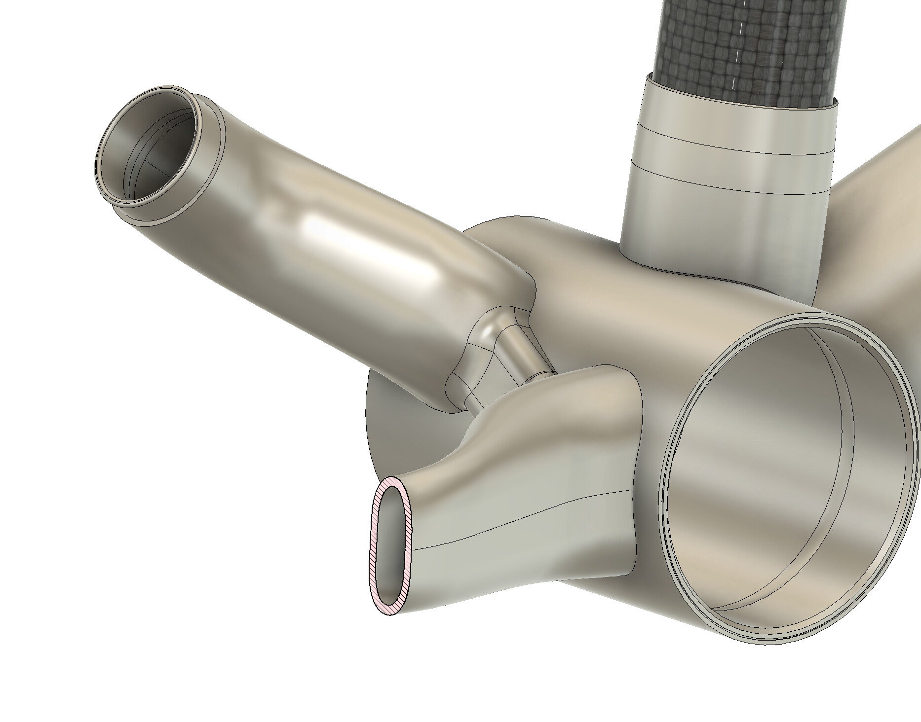
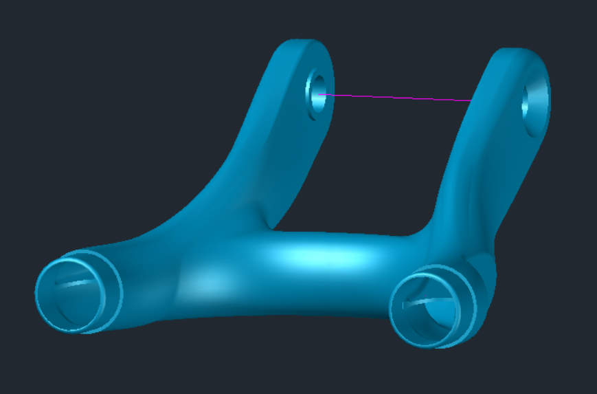
On the most recent gravel bike I made, I’ve noticed that the lateral stiffness in the rear end leaves something to be desired. It’s not awful, but I’d like to stiffen it up a hair for V2 which will be going to a customer. The obvious weak link in the stiffness chain is the drive side of the chainstay yoke.
At its narrowest, this is a 9.6mm wide oval with a 1.2mm wall thickness. Compared to the rest of the chainstays at Ø22.2 x 0.9mm wall, that’s a pretty huge reduction in stiffness. I’ve managed to eke out another 0.7mm of width for V2 but even if I bumped the wall thickness to 1.5mm, it would still be pretty noodly.
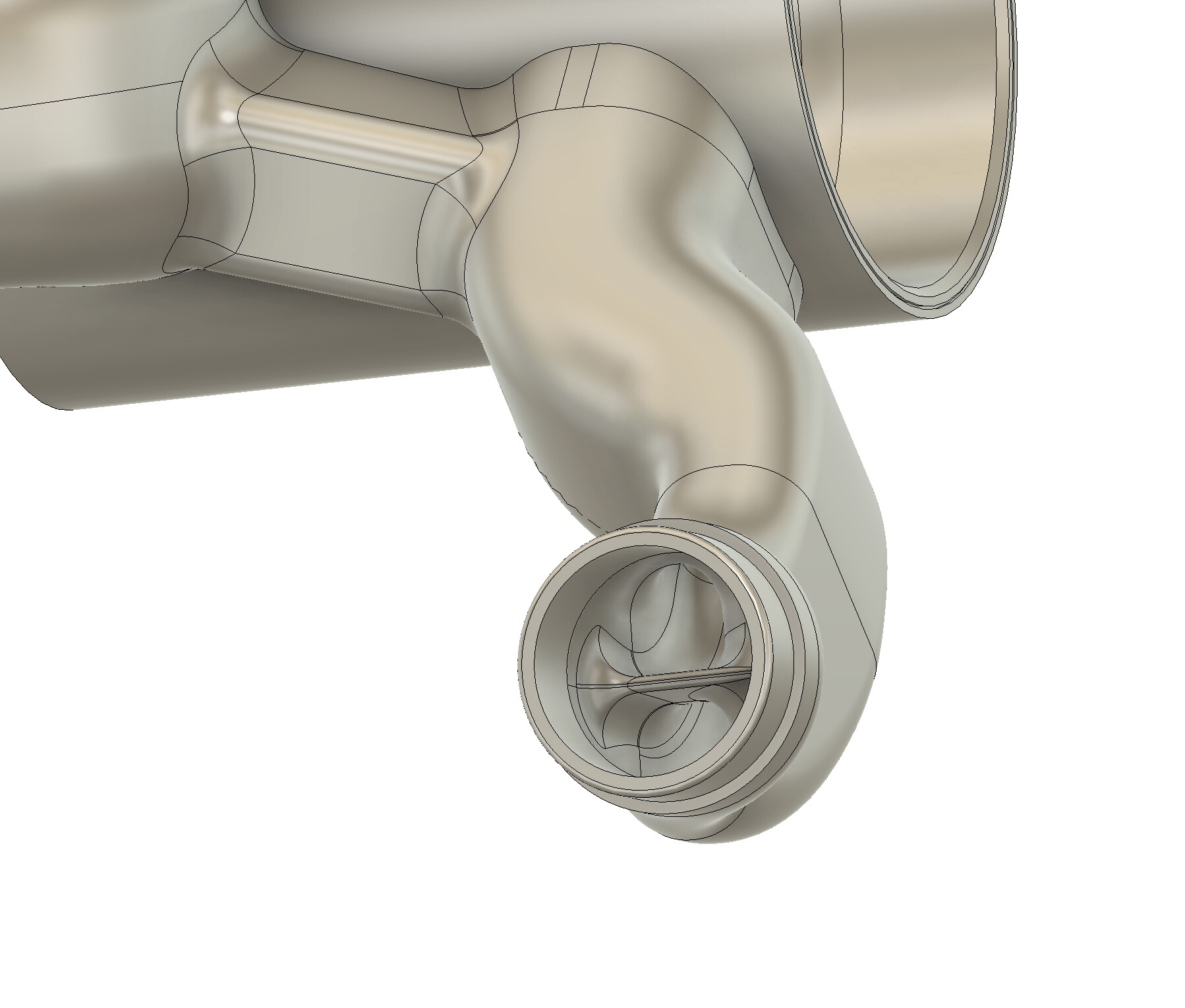
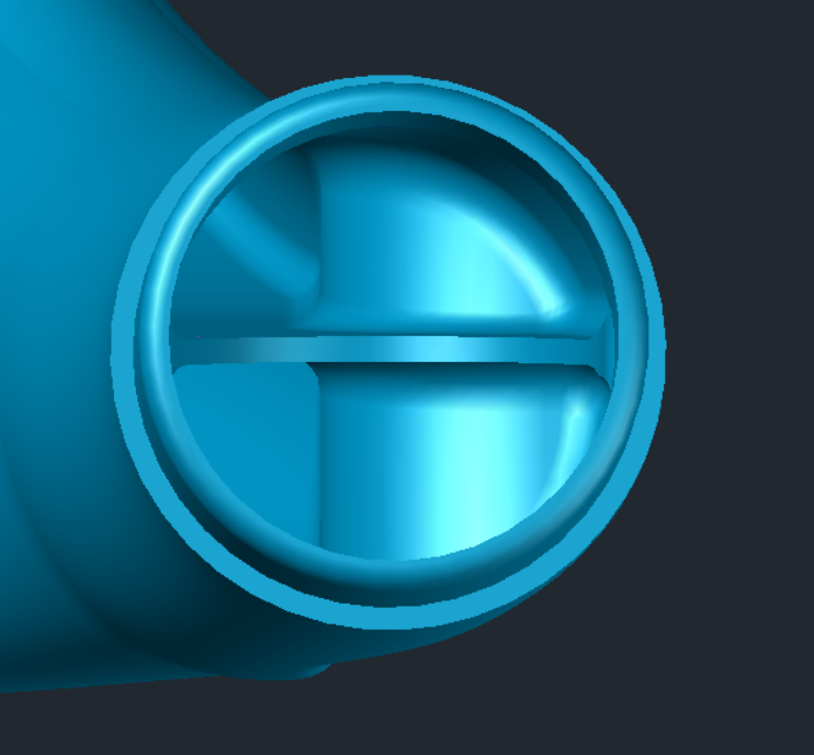
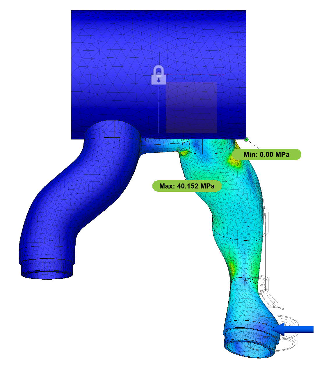
I’ve considered adding a horizontal rib through the narrowest section of the yoke but am worried that would create a pronounced stress riser even with the large fillet:
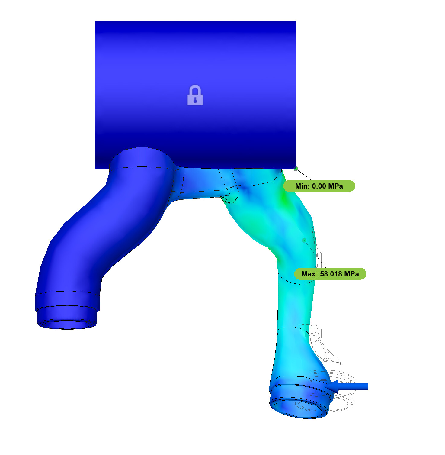
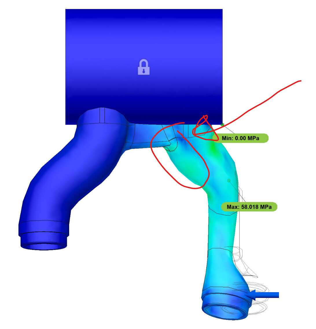
The numbers there are truly made up! This is my first time using FEA with Fusion. I think I had it set up as a force of 100N horizontally applied to the chainstay-facing end of the yoke. I’m more interested in relative stiffness (which I think is proportional to displacement if the force stays the same?).
What I would do is:
Complete the fusion chainstay+seatstay design
Have the rear axle as a fixed point and apply lateral pressure on the BB center (if you want to be precise you could design a lever to mimic a crank and put pressure at the end of the crank)
My feeling is that 58MPa are too many and that in reality your sensed flex is more distributed along the chainstay - that said - you may be right that the yoke is the weak point.
The amount of force doesn’t matter as long as you are comparing shape A to shape B. Linear elastic FEA is linear, as the name implies…
I wouldn’t trust the stress distribution on the surface though, unless I have seen the mesh density and element edges, don’t know if you can see that in fusion. Usually, the automatic mesh generation produces quite coarse tetrahydal elements which tends to smooth the stress display across more radical changes in wall thickness or curvature so that can be misleading.
If you want to use FEA to identify stress risers, you’ll want to ensure that you have a sufficiently refined mesh – typically this is done by evaluating increasingly fine mesh densities until your peak stress converges or you identify a singularity. Fusion does allow you to control some mesh size/shape parameters and introduce local mesh refinement, but the control is nowhere near as good as pro software. If you experiment with refining the mesh, make sure you select the entire body when adjusting the size. Sometimes Fusion will grab faces or edges and this can result in a wonky mesh. Honestly, with the fillets, I’m not sure if that rib is any worse a stress riser than the transition from the printed yoke to the chain stay tube. Like @Luniz82 says, as long as you’re making a relative comparison having well defined loads and boundary conditions is not too important as long as they’re somewhat representative. Also, with these comparisons it’s important to keep the magnitude of the change in mind. 30% of 10mm is probably noticeable, 30% of 1mm is probably not. This is where a somewhat representative model is more useful.
I think I’ve mentioned this before, but I’m skeptical that internal ribs are better at increasing stiffness than just adding extra material to the wall. A while back I did some simple hand calcs and it looked like for certain sizes/shapes you could get a similar increase in stiffness if you took the volume of rib material and just added it to the wall thickness instead. Increasing the wall thickness is probably better for fatigue, too.
Did you follow through with the 34.9mm DT for that bike? That’s a pretty small OD for titanium, and could also be the source of the flexiness you’re experiencing. In order for the BB to move, the DT also needs to move. A 9.6mm wide neck for your yoke doesn’t sound too extreme compared to what folks achieve with dimpled tubes.
A couple of napkin engineering thoughts. I added a rib to my swingarm yoke the same way as you have modelled. In my mind it seemed like the ideal way of adding more transverse material but as noted above sometimes just have a thicker wall can do the same thing. Also note that ‘rear end flex’ starts at teh head tube and ends at the rear axle. The whole frame flexes between those two points. So what feels like the rear waggling around from the BB back it could actually be the DT flexing. I would dive into the whole system that singling out one spot if you havent investigated that yet.
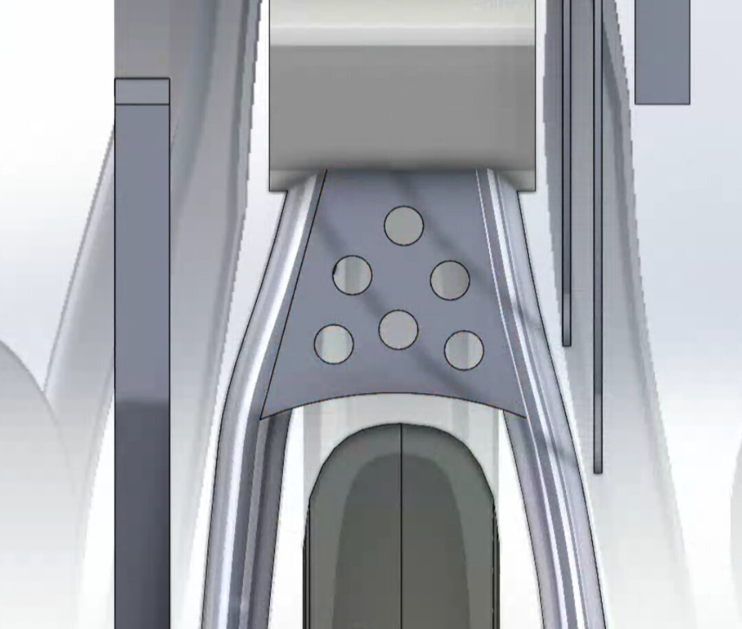
Below is how I did mine and they are definitely stiff enough. Though my cross section is a bit wider than you have.
I used a Ø38.1mm DT and the front triangle feels pretty stiff. But now you’ve got me curious and I’ll try to see if I can quantify the frame flex I’m perceiving. It might just be the Berd spokes + stupid light carbon rims flexing.
Thanks for the Fusion FEA tips! I’ll try to refine my model tomorrow and see if that illuminates anything.
@matt@Luniz82@photon are totally right, the mesh size makes FEA more complicated. That is why I don’t trust FEA with thin tubes, but blocky yokes (the one I posted is mostly solid) should yield more reliable results.
I would guess this is the likely culprit. I’m always surprised by how different wheels can feel.
If you put “plates (with holes)” (or the 3d print equivalent of that) at the top and bottom like in the picture above it creates box section that is very stiff laterally. The problem with that may be that lateral stiffness drops again where the tubes are ovalized the most (at the tire - chainstay choke point) because that’s where the plates end. This could concentrate the stress at this point. But what it would definitely do is bring a lot of lateral stiffness for relatively little weight gain (if you make holes or similar into the plates) and it would probably also lessen the stress at the chainstay - bottom bracket joint.
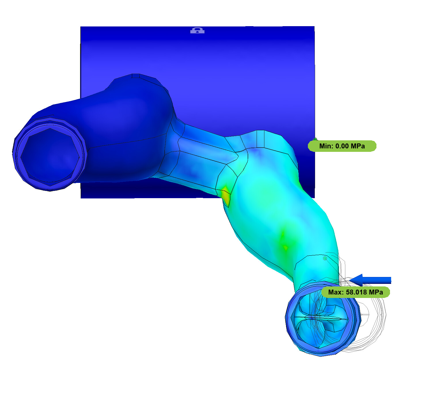
I increased the mesh resolution in the leg to hopefully yield more accurate results.
In playing around with various options, adding a rib certainly helps a ton (~30% stiffer), but the width of the rib doesn’t have a huge impact. Changing the overall wall thickness helps too, going from 1.2mm to 1.5mm was another 30% increase in stiffness.
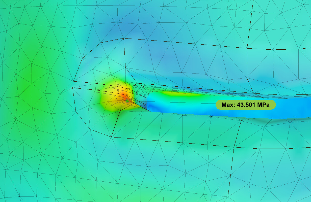
One thing I was not too thrilled with is the stress concentration at the start of the rib:
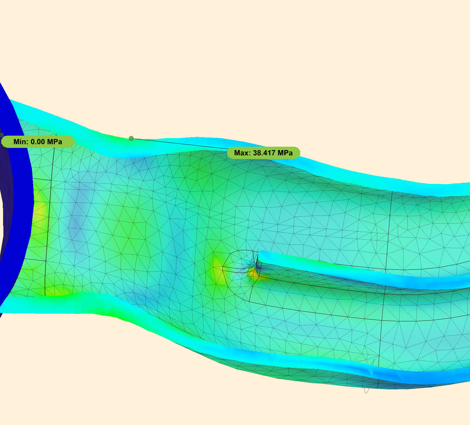
As one might expect, playing around with the various loft profiles has a big impact. I was able to increase the width of the middle profile a bit to eke out a bit more stiffness:
This incorporates a wider mid profile, a 1.3mm wall thickness (diminishing returns above this), and the single horizontal rib through the thin section. The stiffness based on these calculations is 2.14x the original which exceeds my goal and I only added 7g of extra material (an 8% increase). There aren’t any obvious stress risers other than the ones to be expected based on the shape and function of the yoke.
I ran about 20 FEA simulations for this that aren’t pictured but my free trial for Fusion’s simulation package has ended and so I gotta call this good enough!
What I did to remove that concentrated stress point you have on your rib is to not have the end perpendicular tp the wall of the yoke. I had teh end curve in and merge with teh wall at a low angle. Of not done FEA on it though to see what that does. Just gut feel engineering from experience.