Welcome to the Kitchen Party Build Log!
Intro:
I intend to use this space to share my experiences with bike/component design and fabrication in hopes that some of my successes and failures can be helpful for others. Since I currently do not intend to ever sell any frames I’m going to share all my Fusion 360 and any other applicable files. This will likely include an excess/overshare of information/images, but I just want to put it all out there. During my day job I rarely get to share any of my work, so sharing all these details is a refreshing exercise. If you have any questions please reach out and I'll do my best to answer them.The Range: 2021
Let’s start with the Kitchen Party Range build. Named after a kitchen range, you know, like a stove. For my first frame I wanted to get the basics down with a relatively straightforward allroad/gravel build. I’m definitely more of a mtb guy and really don’t have a great grasp of bike geo for this category so I loosely based the geo on the specialized diverge. Also I just want to get it out there that I am aware my welds are atrocious. This bike was the first thing I’ve ever welded beyond practice joints so there’s a lot of room for improvement.
Design Goals:
- 12 x 142 thru-axle compatibility
- UDH compatibility
- Aggressive amount of water storage
- Mounts for a strapless front triangle frame bag
- Flat mount for modern hydraulic brakes
- Rugged frame so I can huck curbs and fly down sketchy mtb trails
- Full internal cable routing
- Internal dropper post compatibility
- Frame weight is just a mindset
Frame Components Purchased
- 1.500 x 68.5mm BSA BB Shell
- Down Tube: (1) 1.50" x 36" x 0.035"WT 4130
- Top Tube: (1) 1.25" x 24" x 0.035"WT 4130
- Head Tube: (1) 1.625" x 12" x 0.120"WT 4130
- Seat Tube Collar: (1) 1.375" x 12" x 0.065"WT 4130
- Seat Tube: (1) 1.375" x 24" x 0.035"WT 4130
- Seat Stays: (2) 0.625" x 24" x 0.035"WT 4130
- Chain Stays: (2) 1.375" x 24" x 0.035"WT 4130
- Plate for Dropouts: 9" x 9" x 0.250" 4130
- “Ride Wrap” protective coating
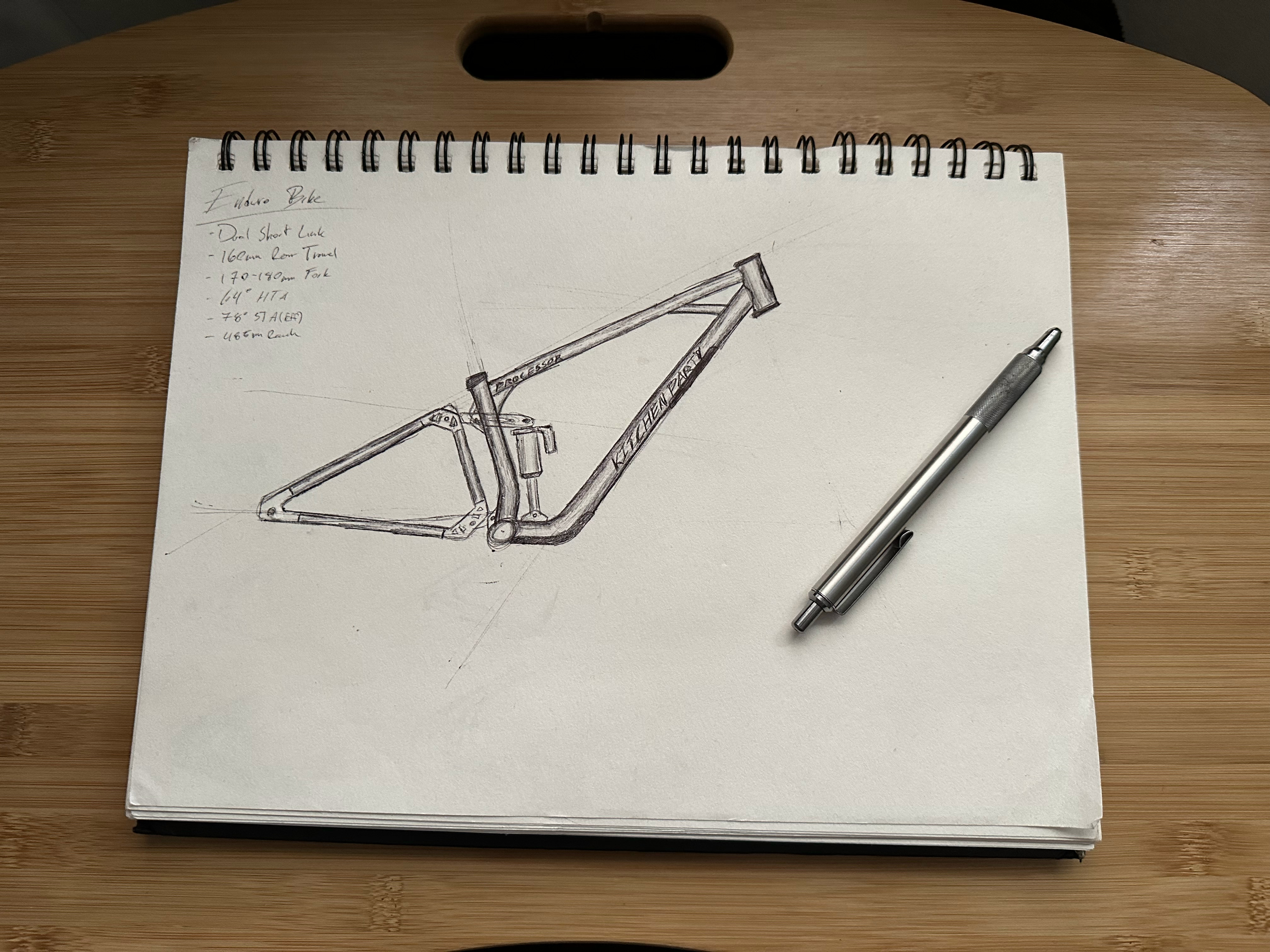
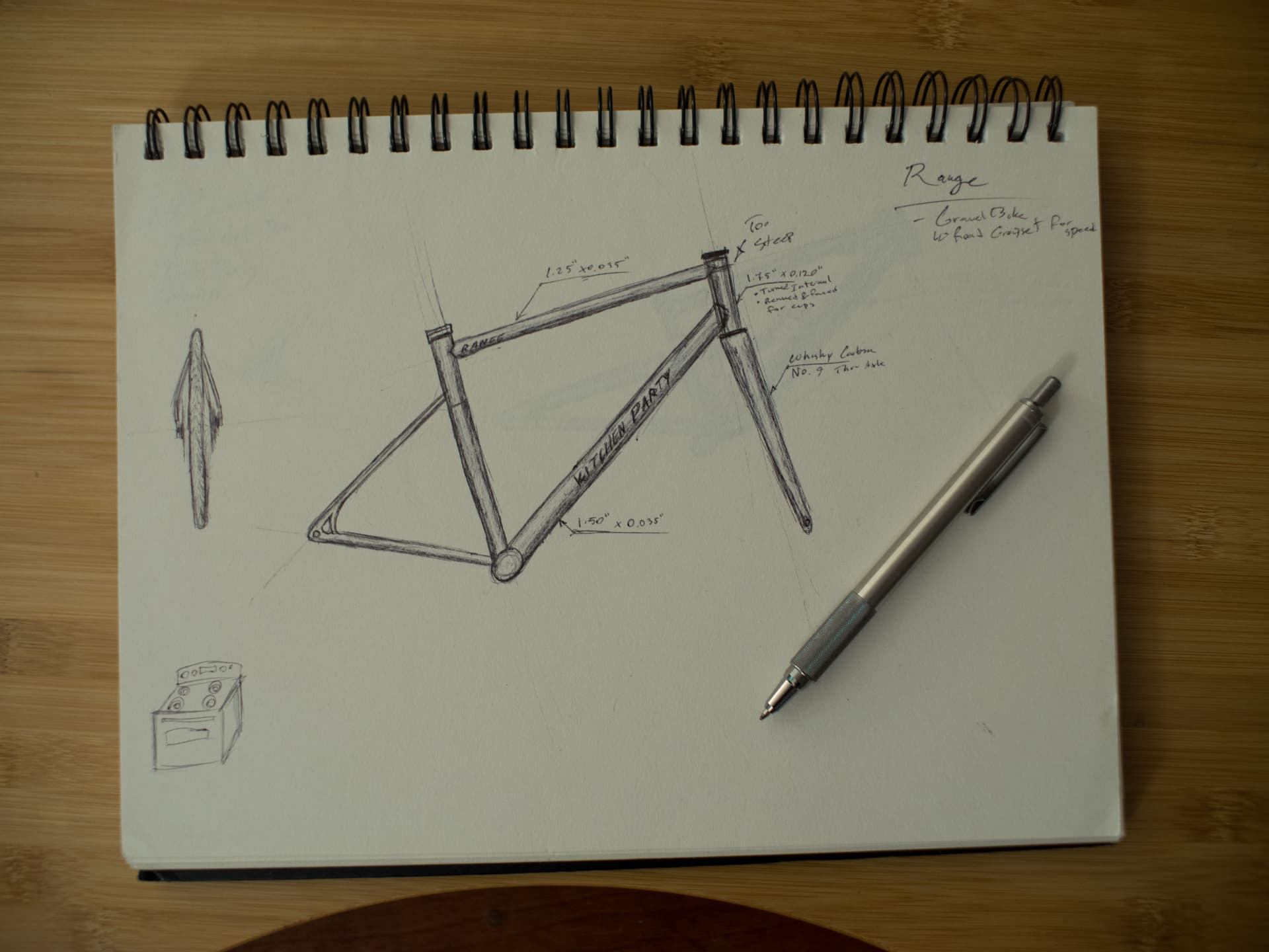
For the longest time I started all my designs in CAD software and felt like I would get too caught up in the details of sketch constraints and it really hindered any creativity. For this reason I’ve been trying to take the approach of starting all designs with iterative sketches to get the overall design form and all ideas out there. Industrial design is a bit of a passion of mine and an area in which I would like to improve.
To build this frame I had to first build a frame fixture. I chose to base this off the cobra frame fixture V1 and got about 90% through the build before I found his instagram and saw he was working through the V2 and planning to start selling them. For this reason I’m going to leave out any details regarding the fixture build, but will strongly recommend his tooling to anyone in the market. In hindsight, I wish I had just purchased a frame fixture from him as that would have saved me a ton of time, would have resulted in a much nicer product, and in the end building my own wasn’t as cost effective as I had anticipated.

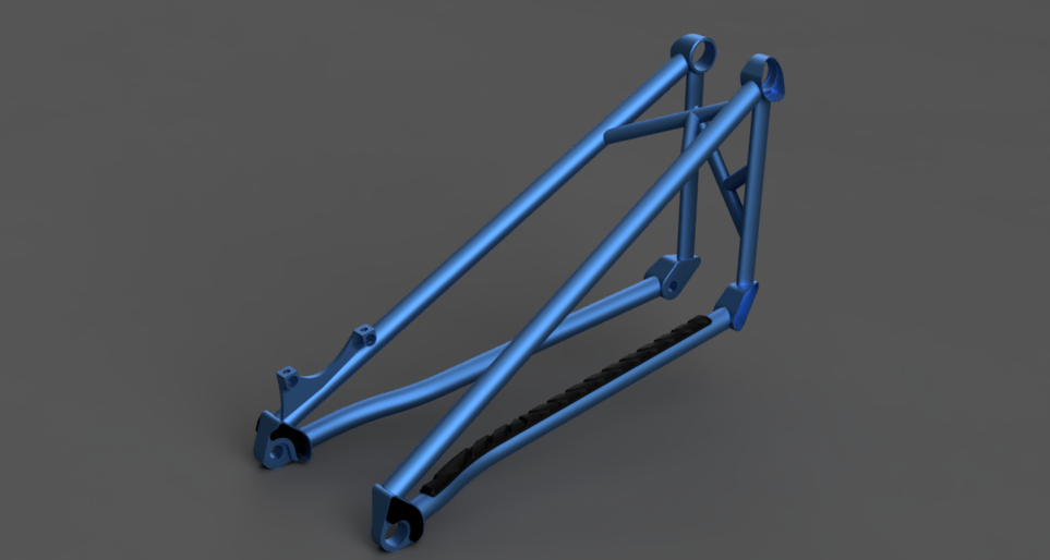
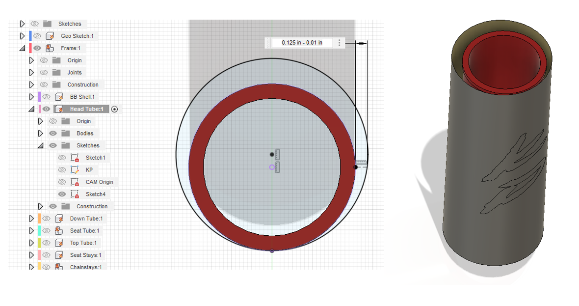
CAD model of the frame build. Take a look at the linked F360 file if you’re interested. I was also happy to see that my modelling process closely resembled what @Daniel_Y put together in his awesome tutorial!
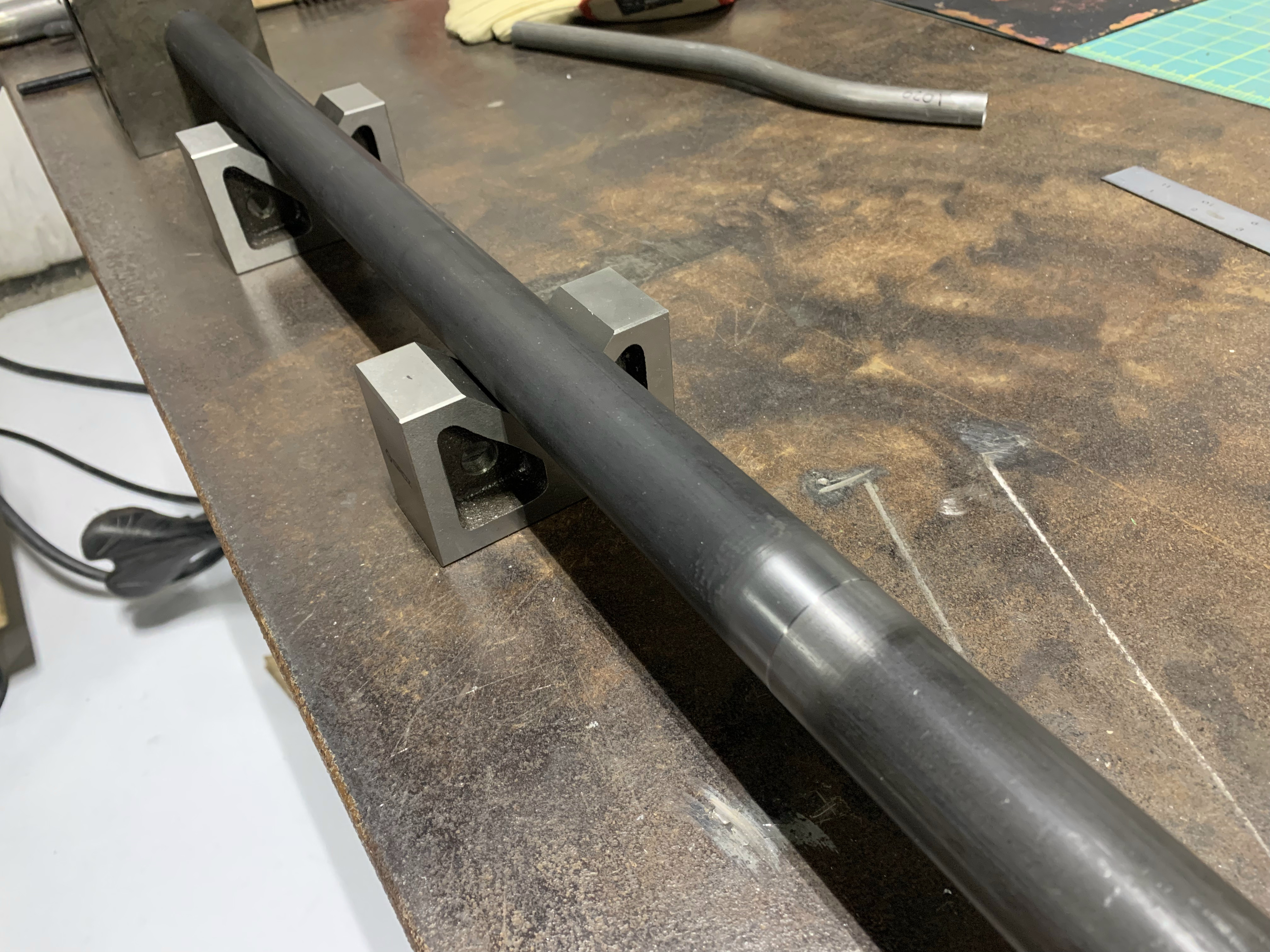
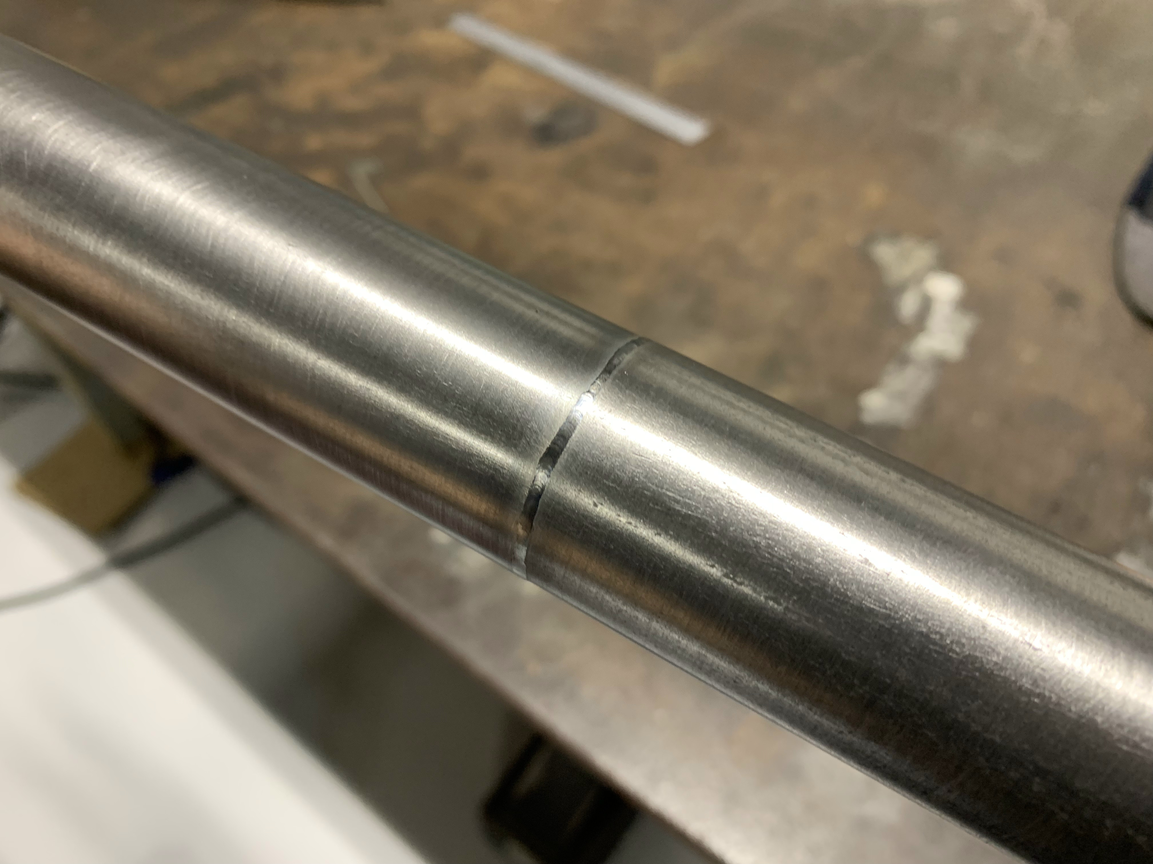
I turned a seat tube collar, aligned it with v-blocks and fusion welded it together.

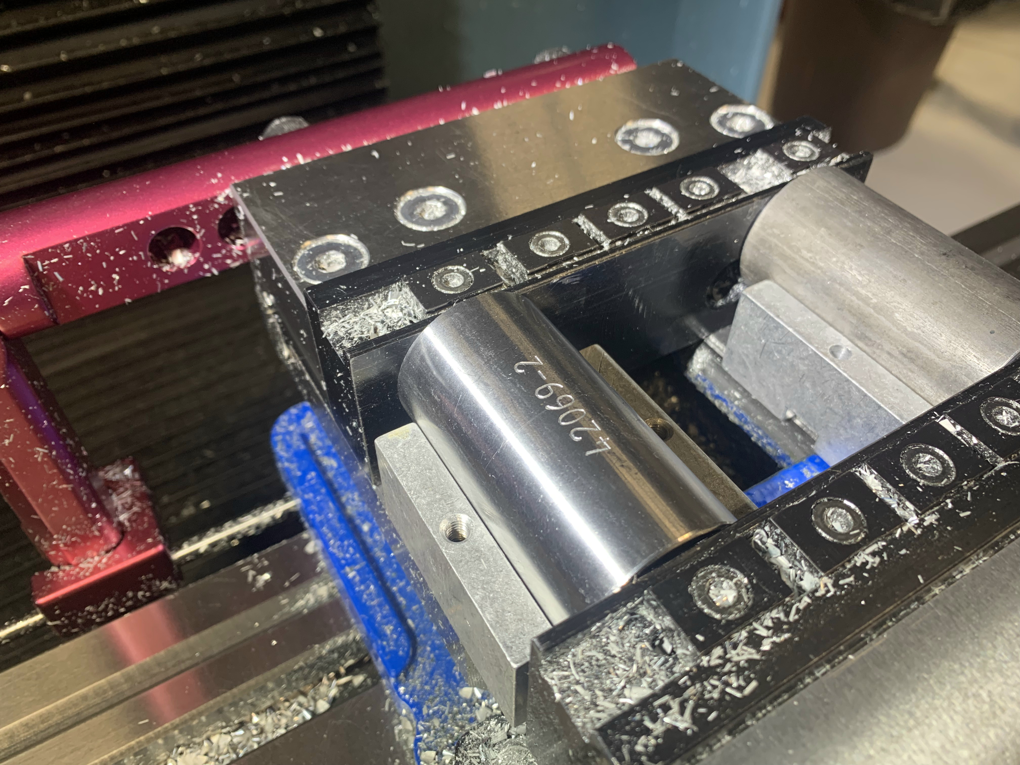
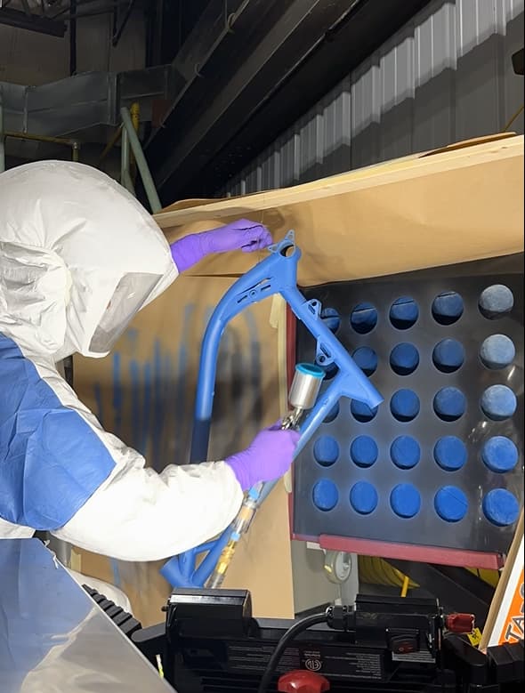
Serial number engraving on the BB. Number chosen for obvious reasons.
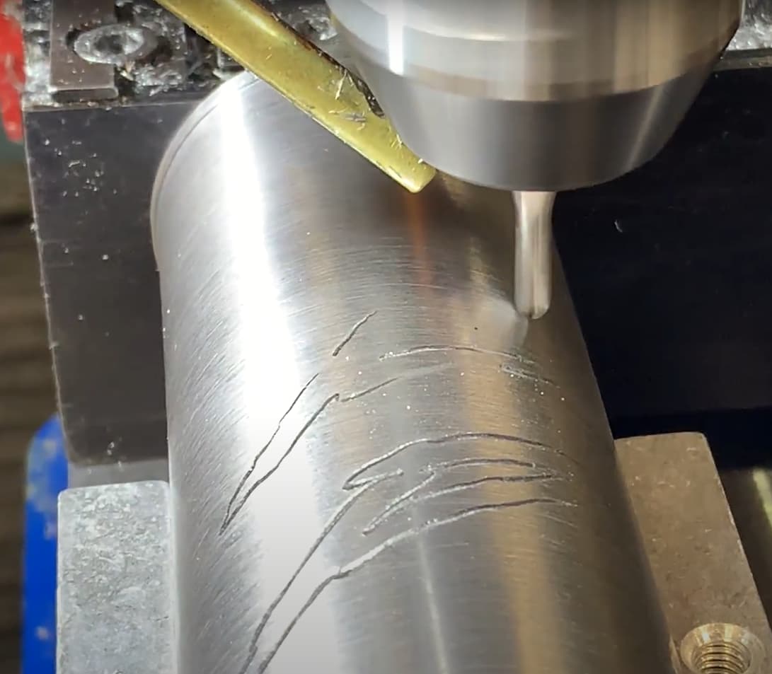
I turned a straight head tube on the lathe and engraved it on the 3-axis cnc mill. This was a bit of a tricky process to figure out to engrave a specified depth on the head tube. I ended up creating a surface tangent to the top of the HT at an offset equal to the tool radius minus the engraving depth. Then used a split surface to map the toolpath to the surface.
Cut and mitered tubes as you’re all familiar with.
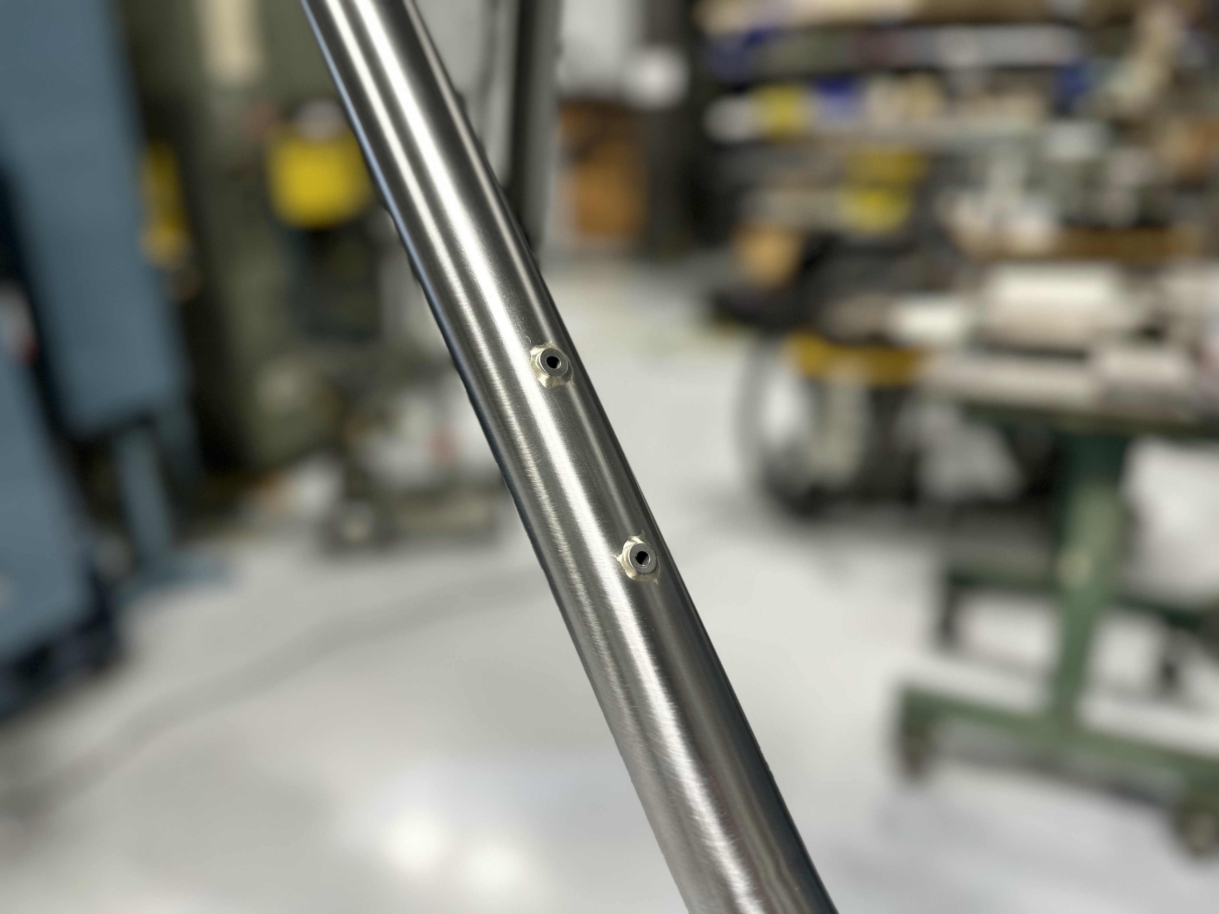
Drilled holes for bosses and milled slots for internal cable routing. Slots were milled at 0.25" width and 0.75" center to center distance. Slots were then hand filed at expected angles for internal tubing.
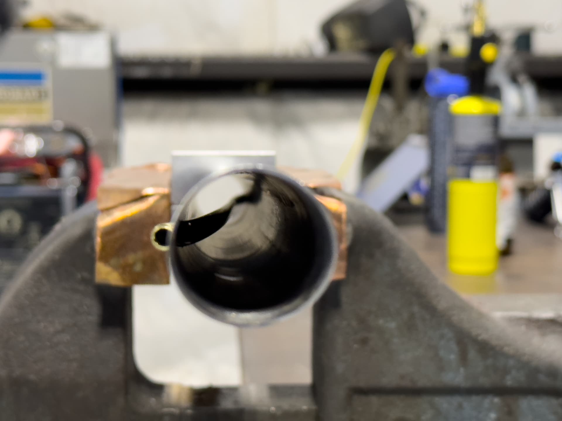
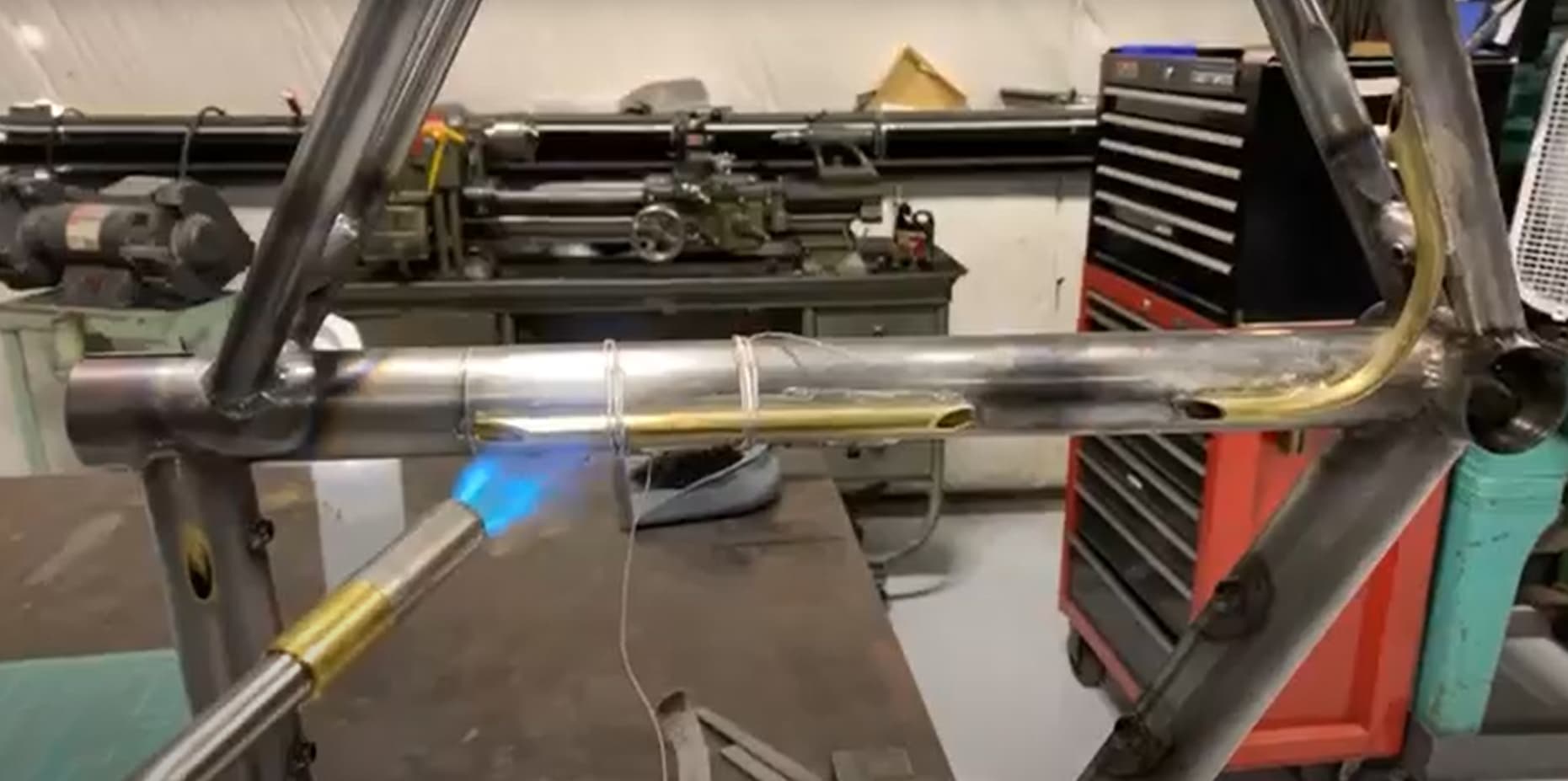
This photo always cracks me up. I can’t not see a surprised fish face. Anyway, internal brass tubing was fit and silver brazed in the top tube. This was brazed with the white flux purchased from framebuilder supply. I used a mapp torch for this process and kept cooking the flux to the point where it would no longer accept any filler. In a later build I found that this brown flux from McMaster Carr was far superior and I had zero issues with it.
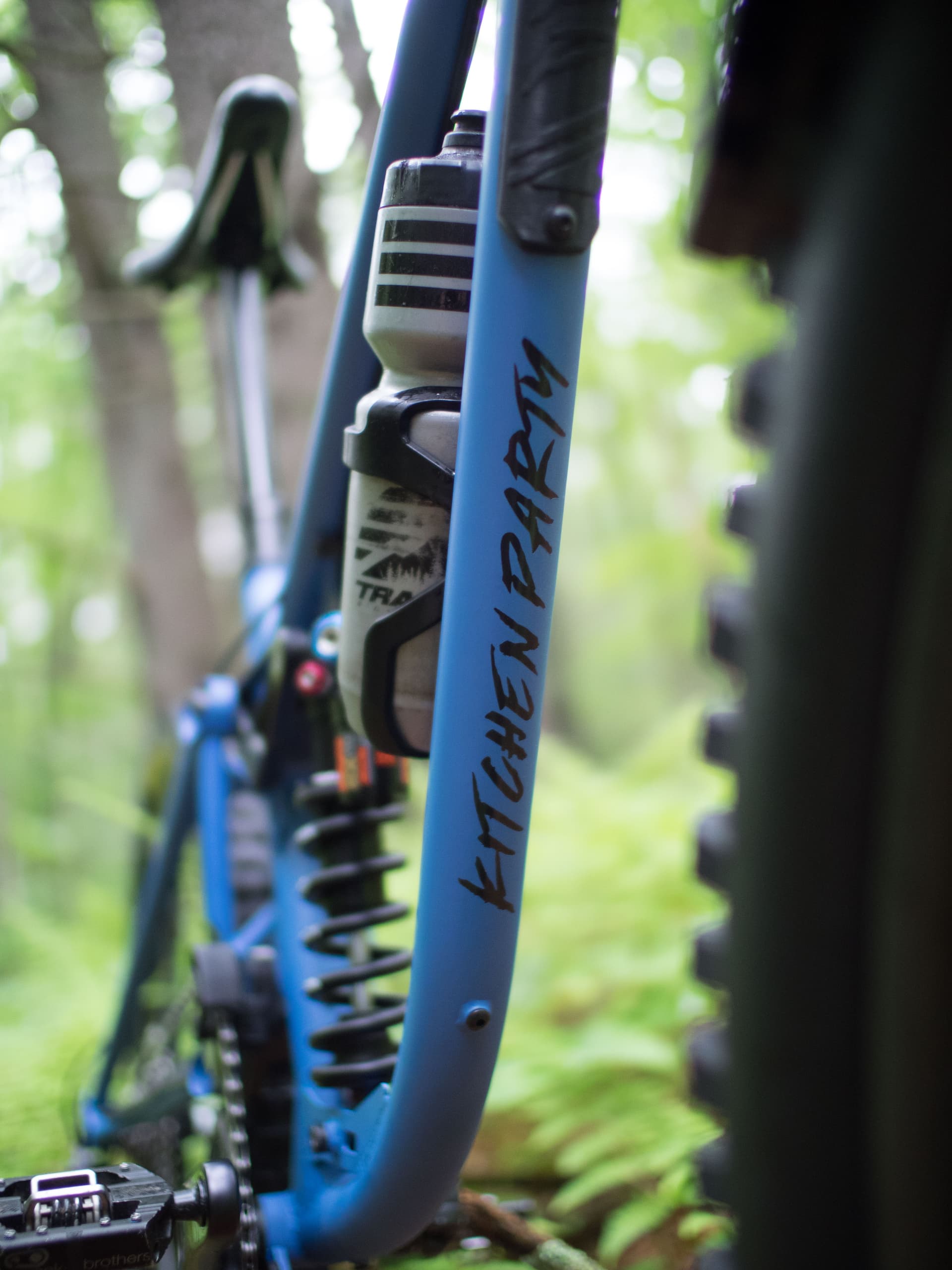
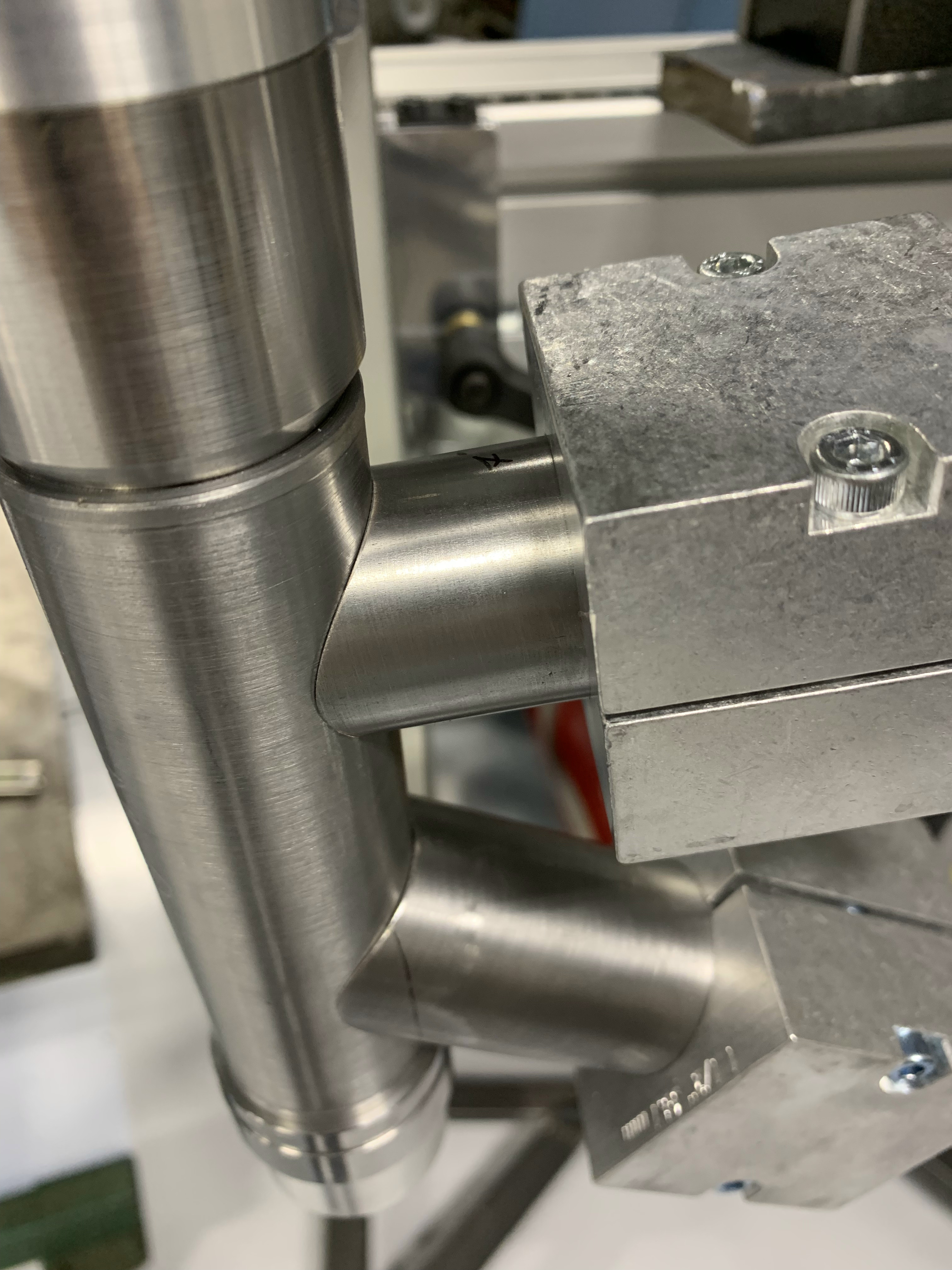
Test fitting water bottles to verify boss locations prior to welding.
Some of the miters were halfway decent!
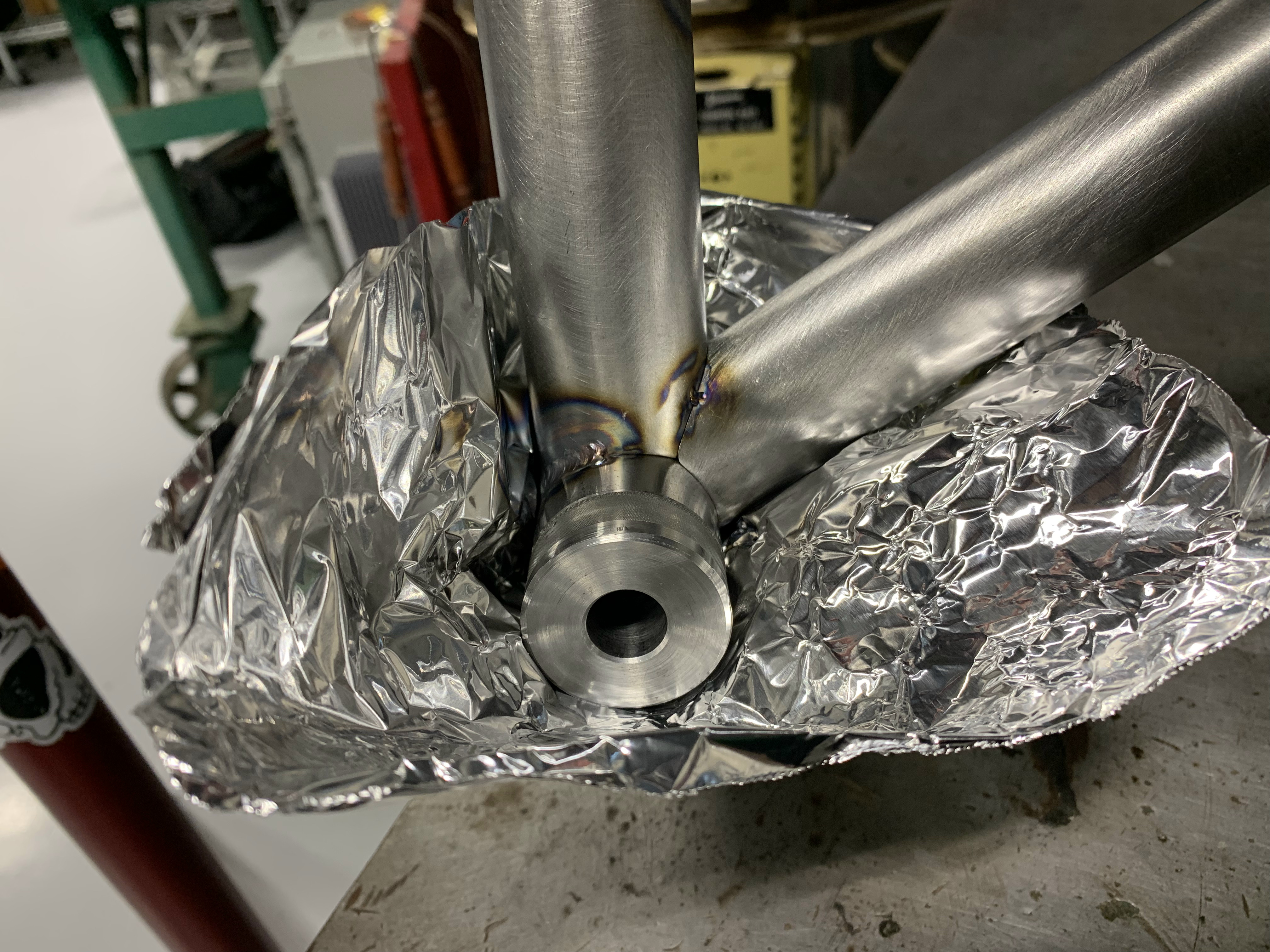
Welding BB junction with aluminum foil argon dam.
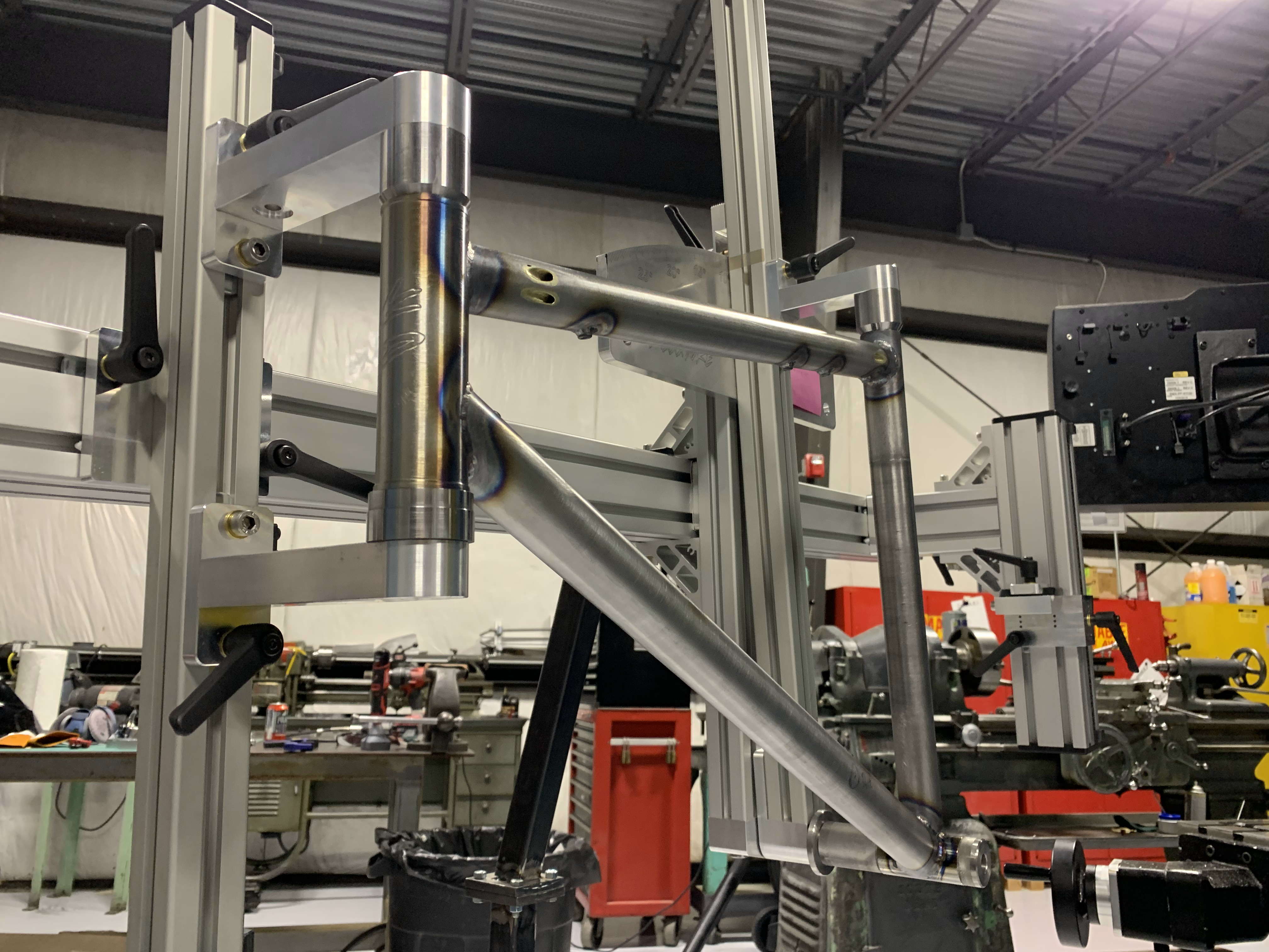
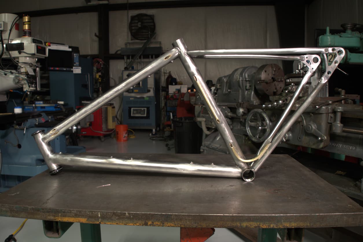
Fully welded front triangle.
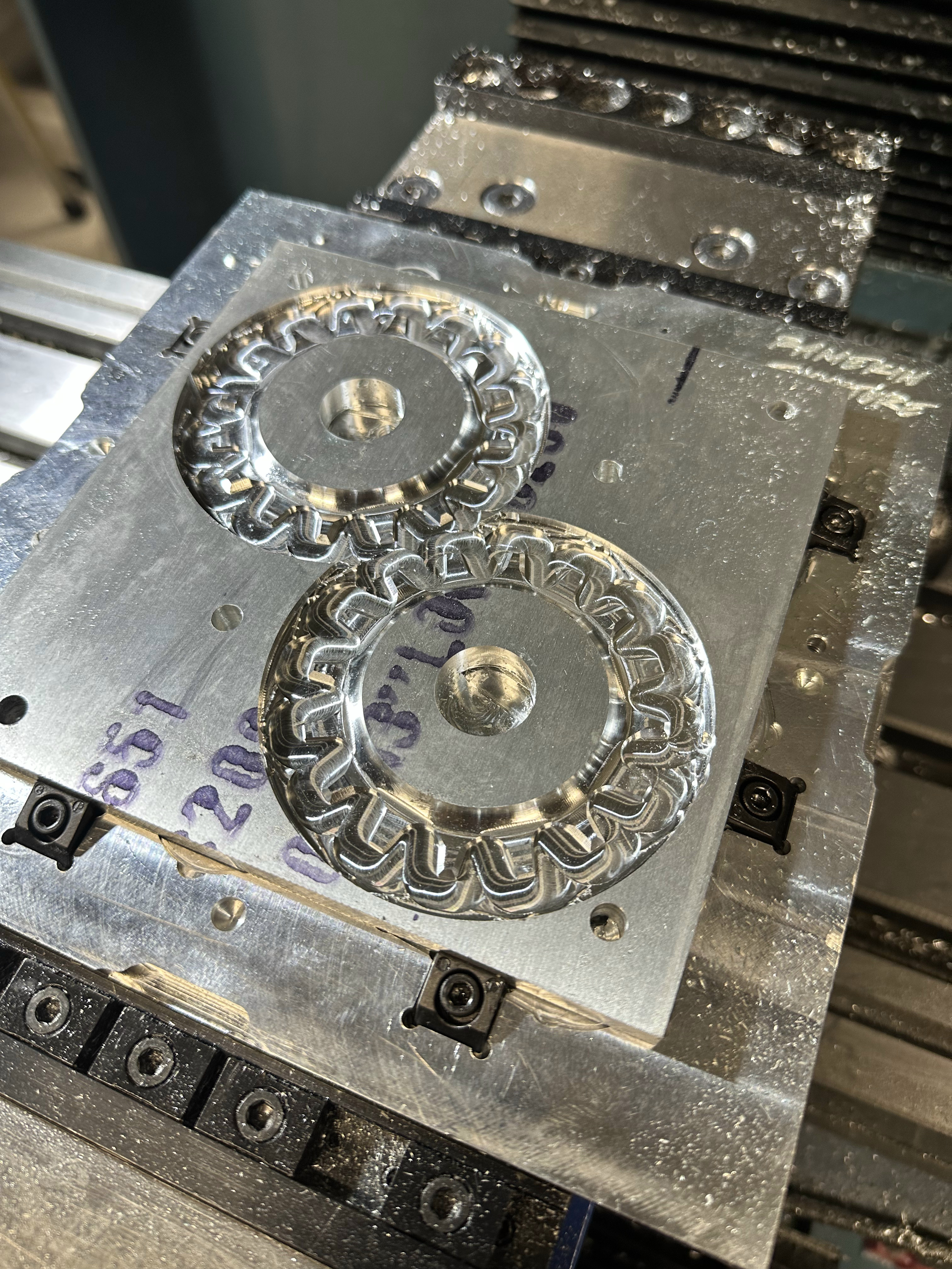
CNC machined rear dropout plates. First time CNC machining any steel.
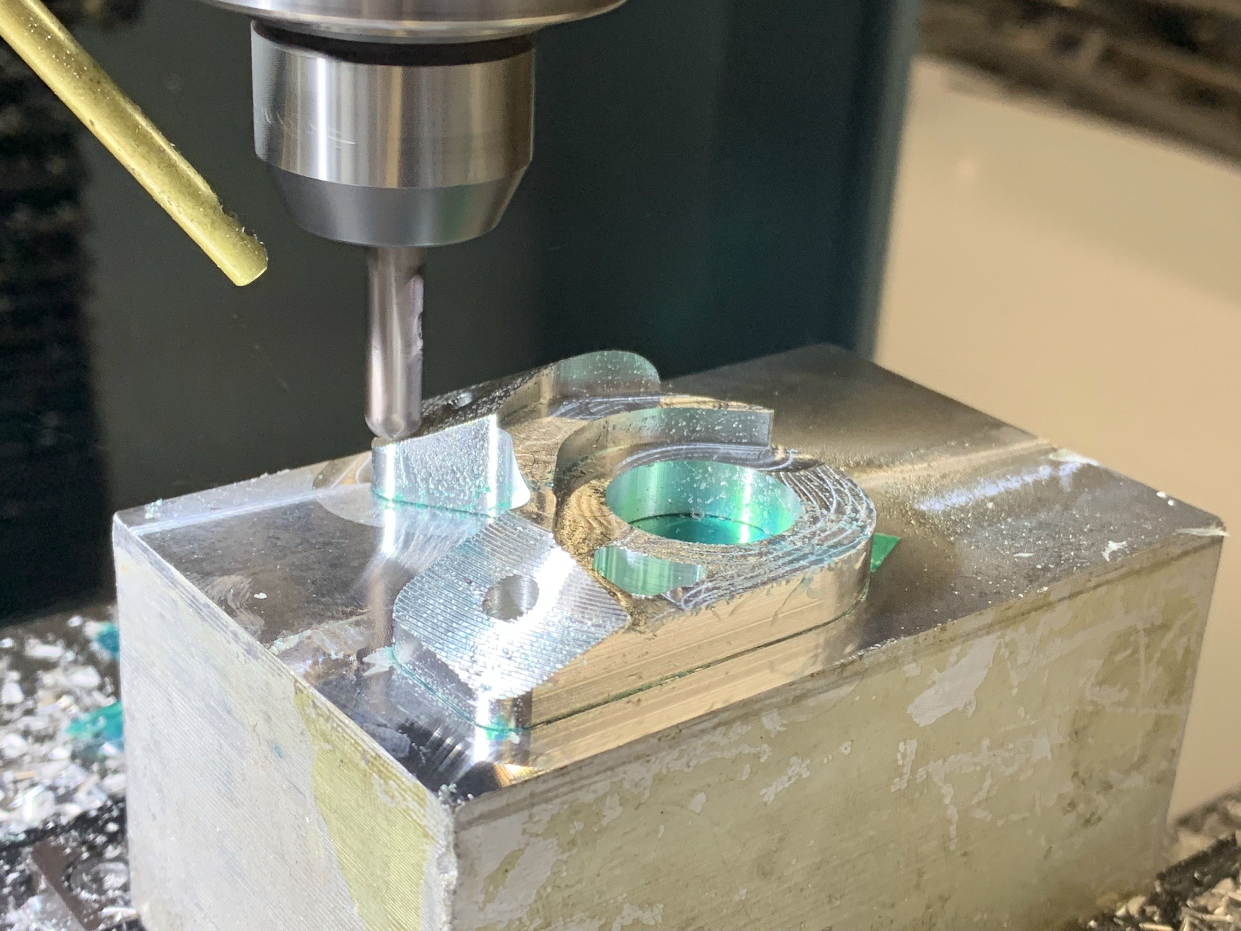
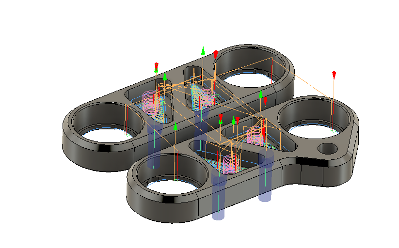
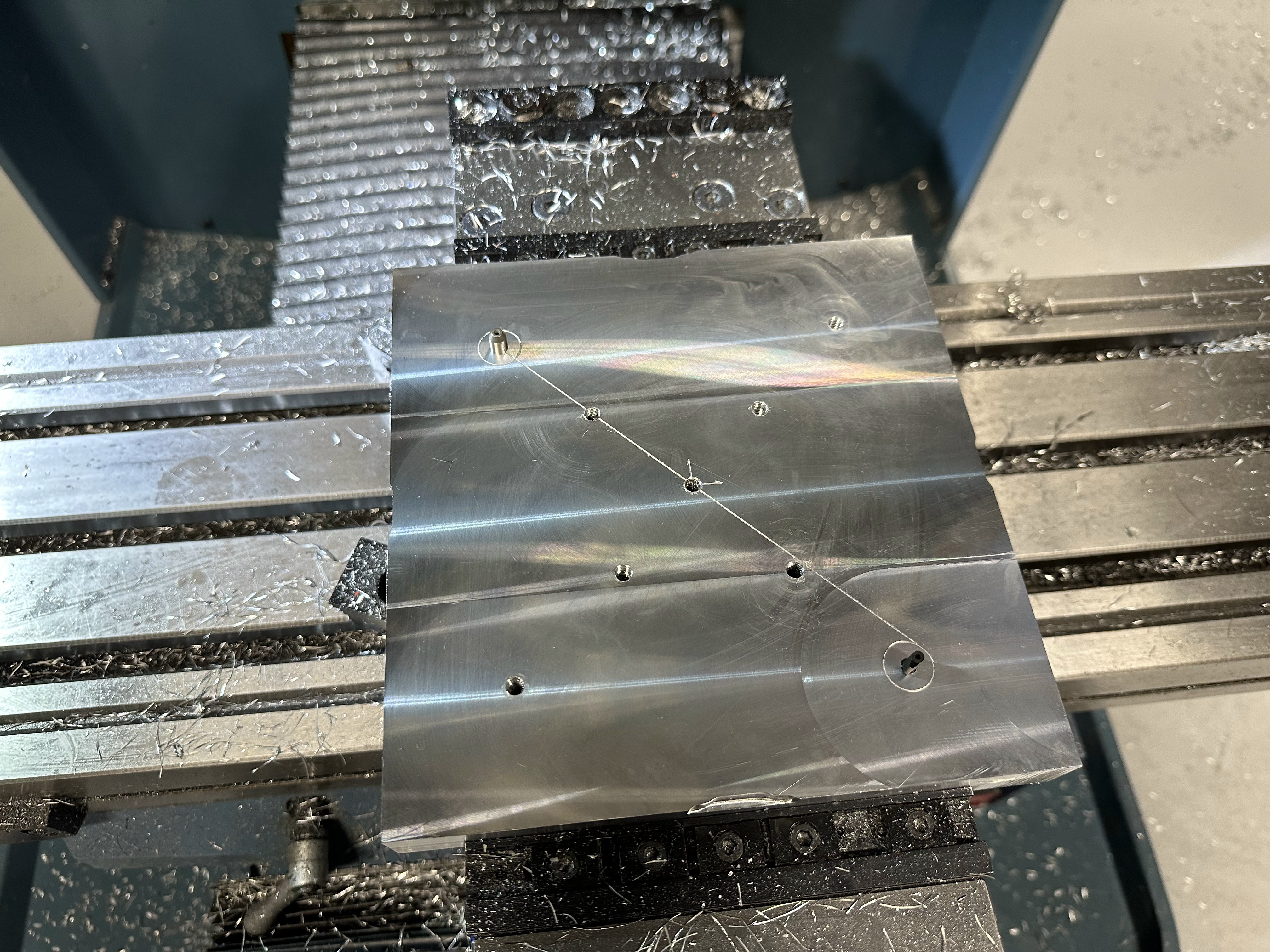
UDH adapter plate. Machined using tape and super glue fixturing method. I cannot recommend this method as I’ve violently thrown enough parts across the shop this way. Apparently I didn’t take any photos of the non-drive side adapter plate machining, but it was done in a similar fashion, but in two operations.
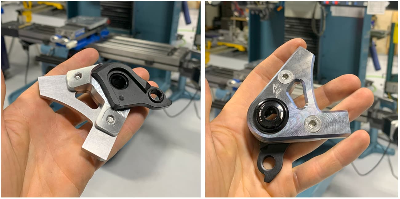
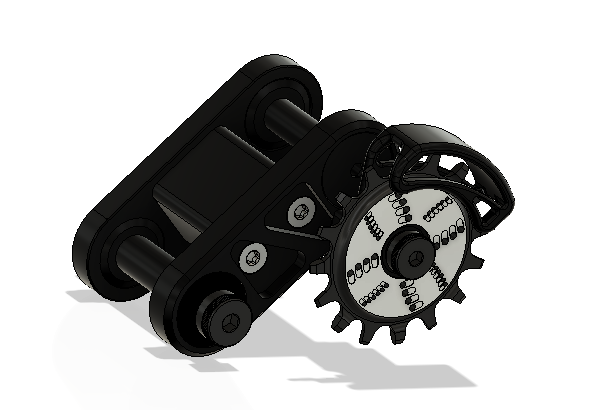
Complete UDH dropout assembly!
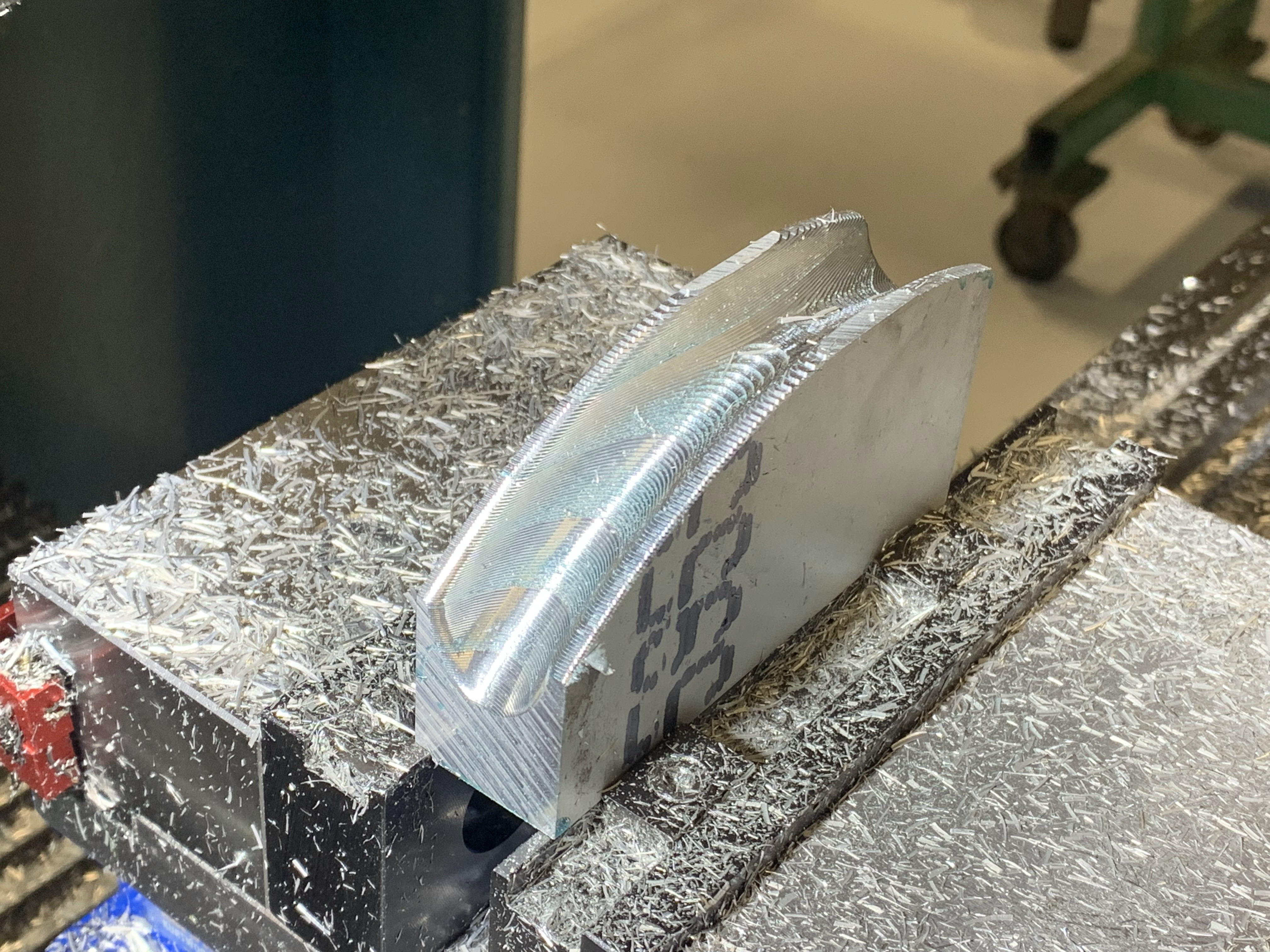
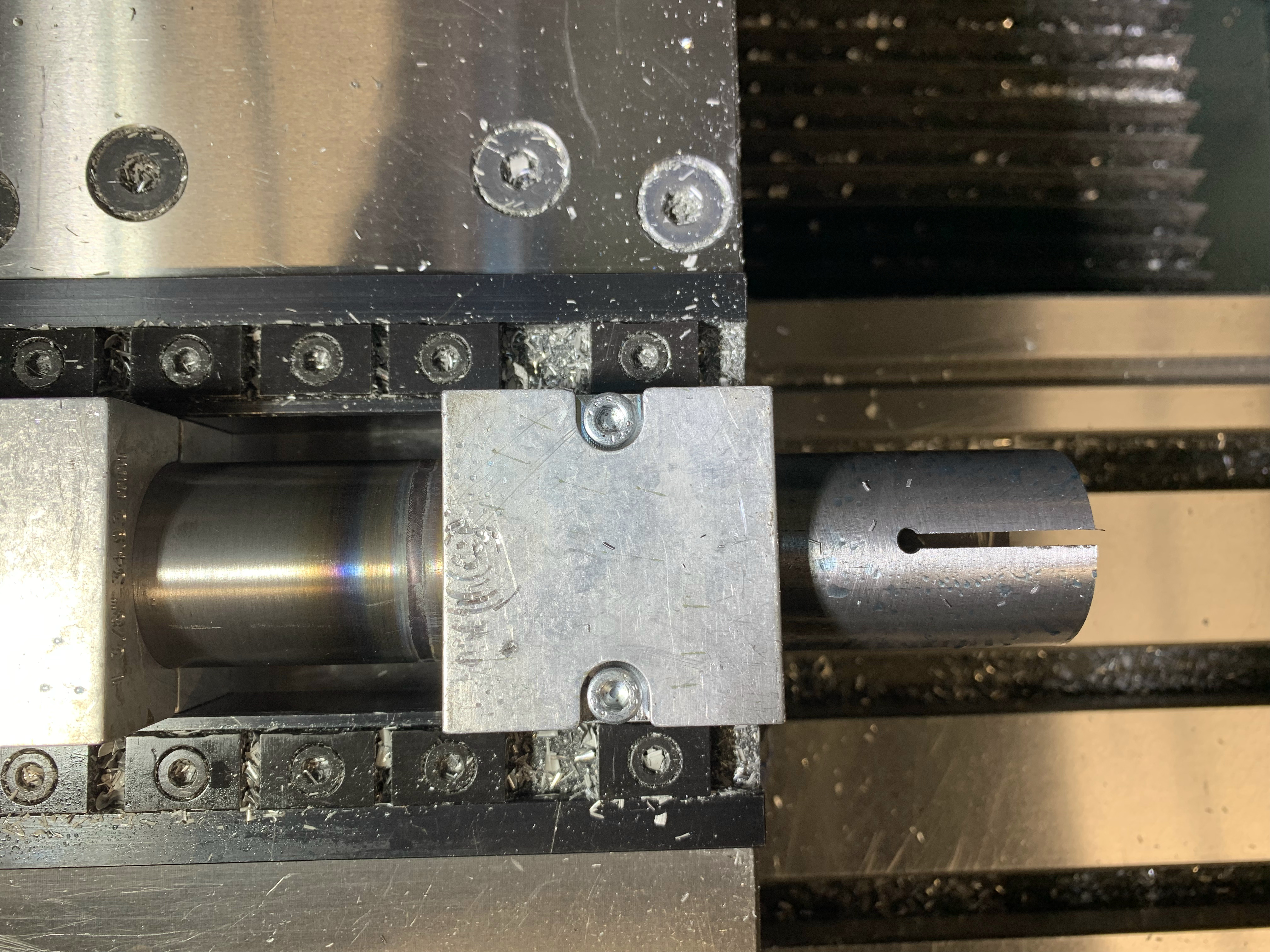
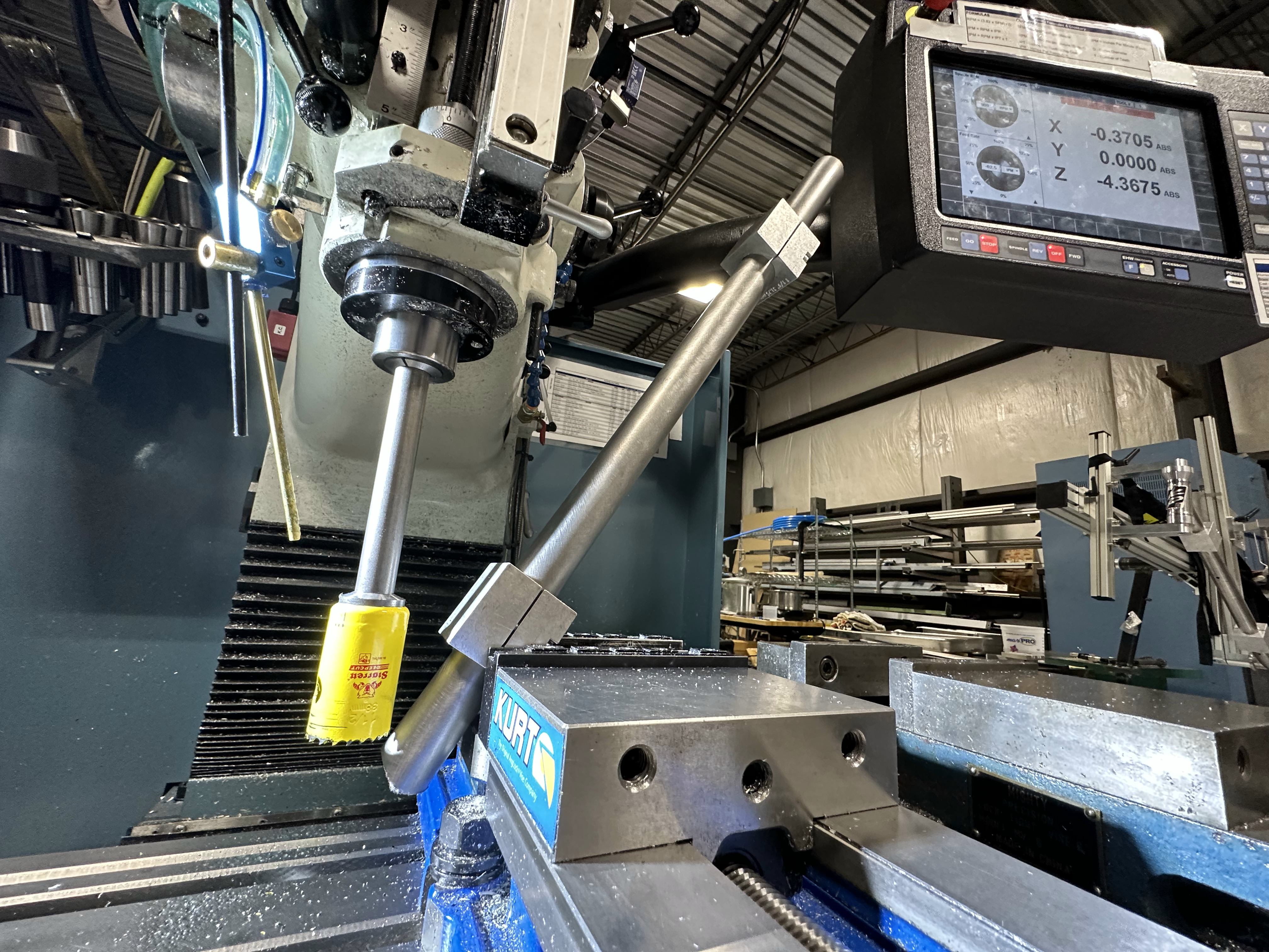
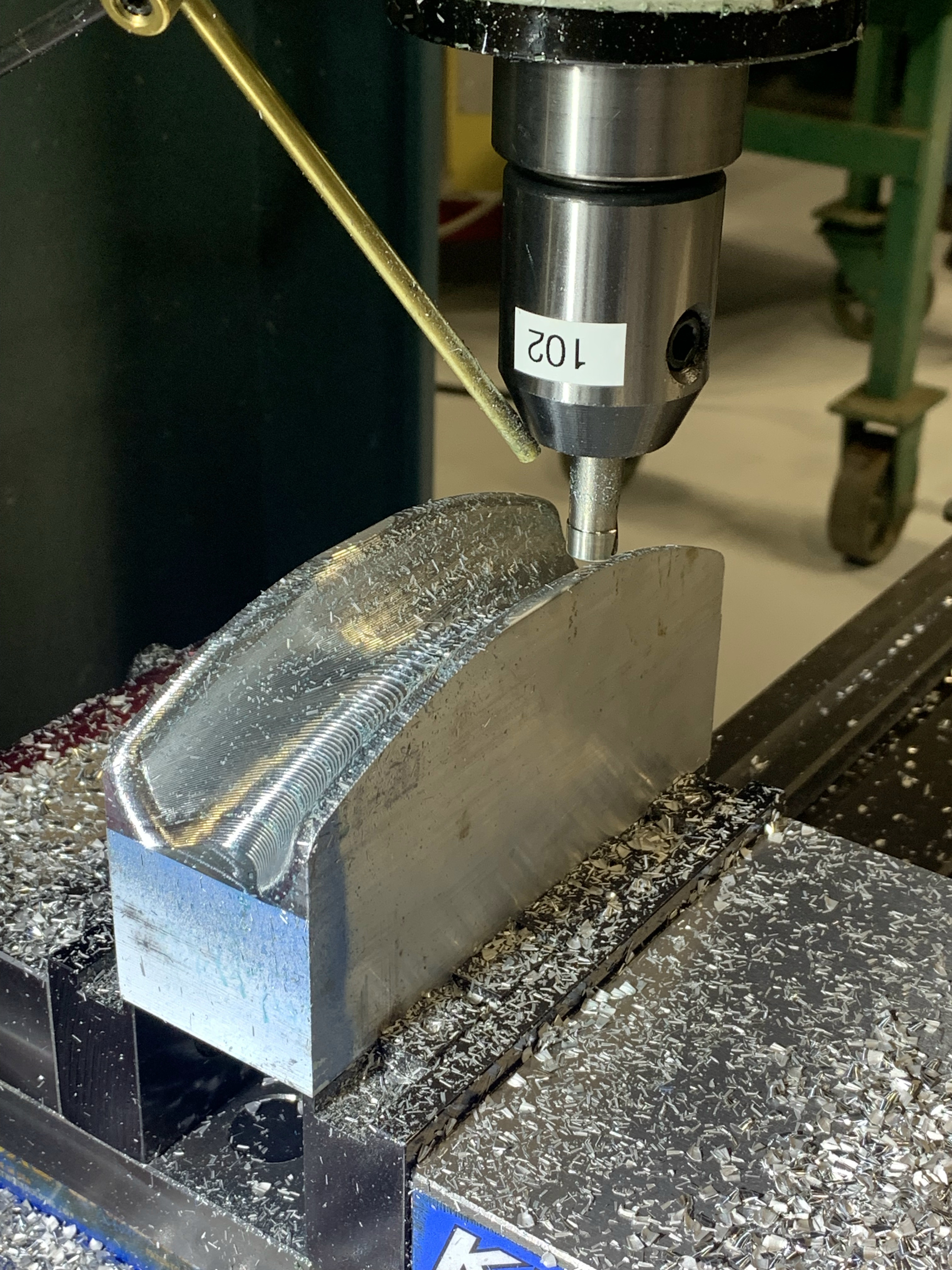
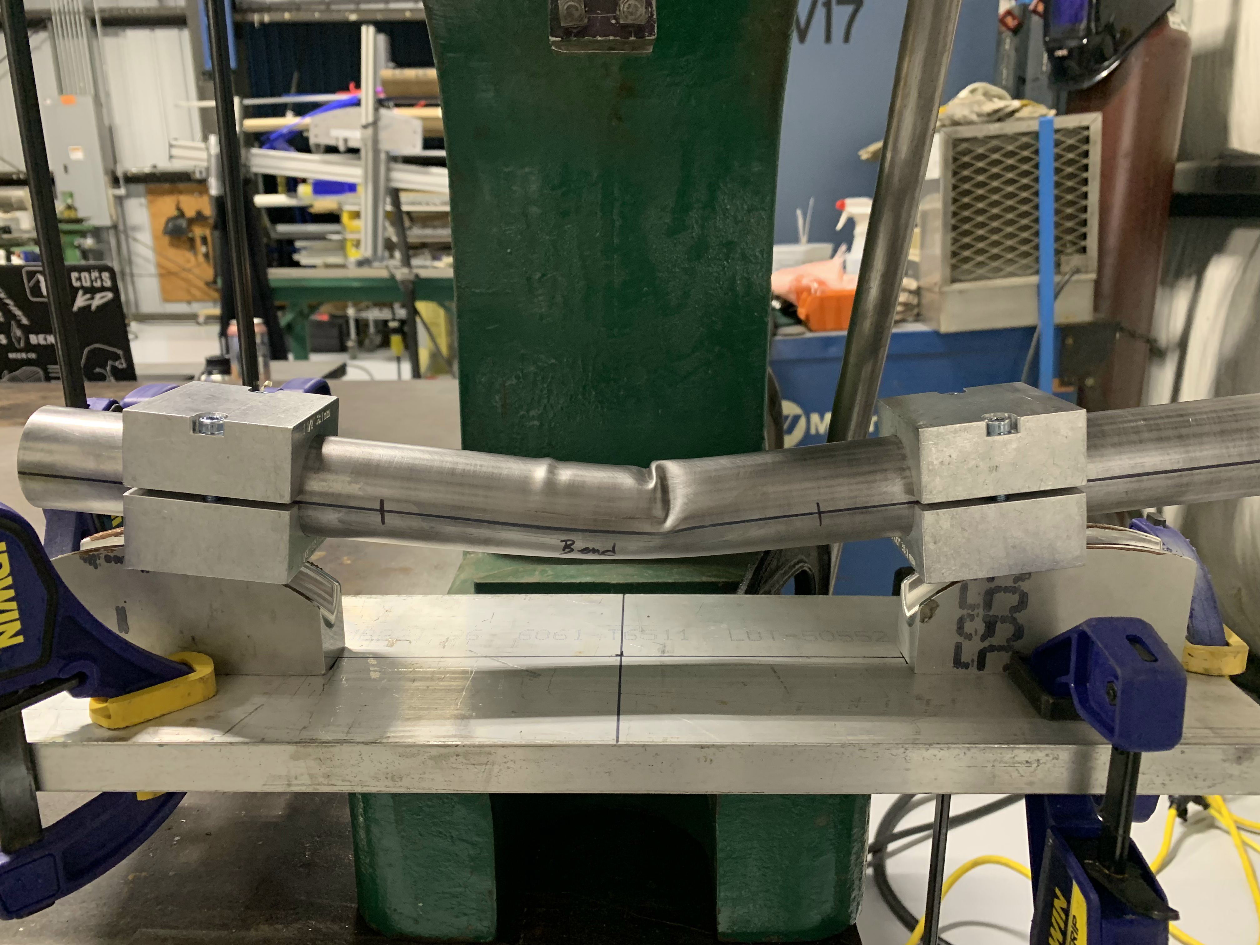
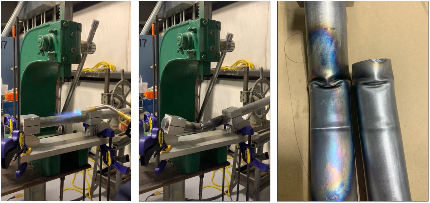
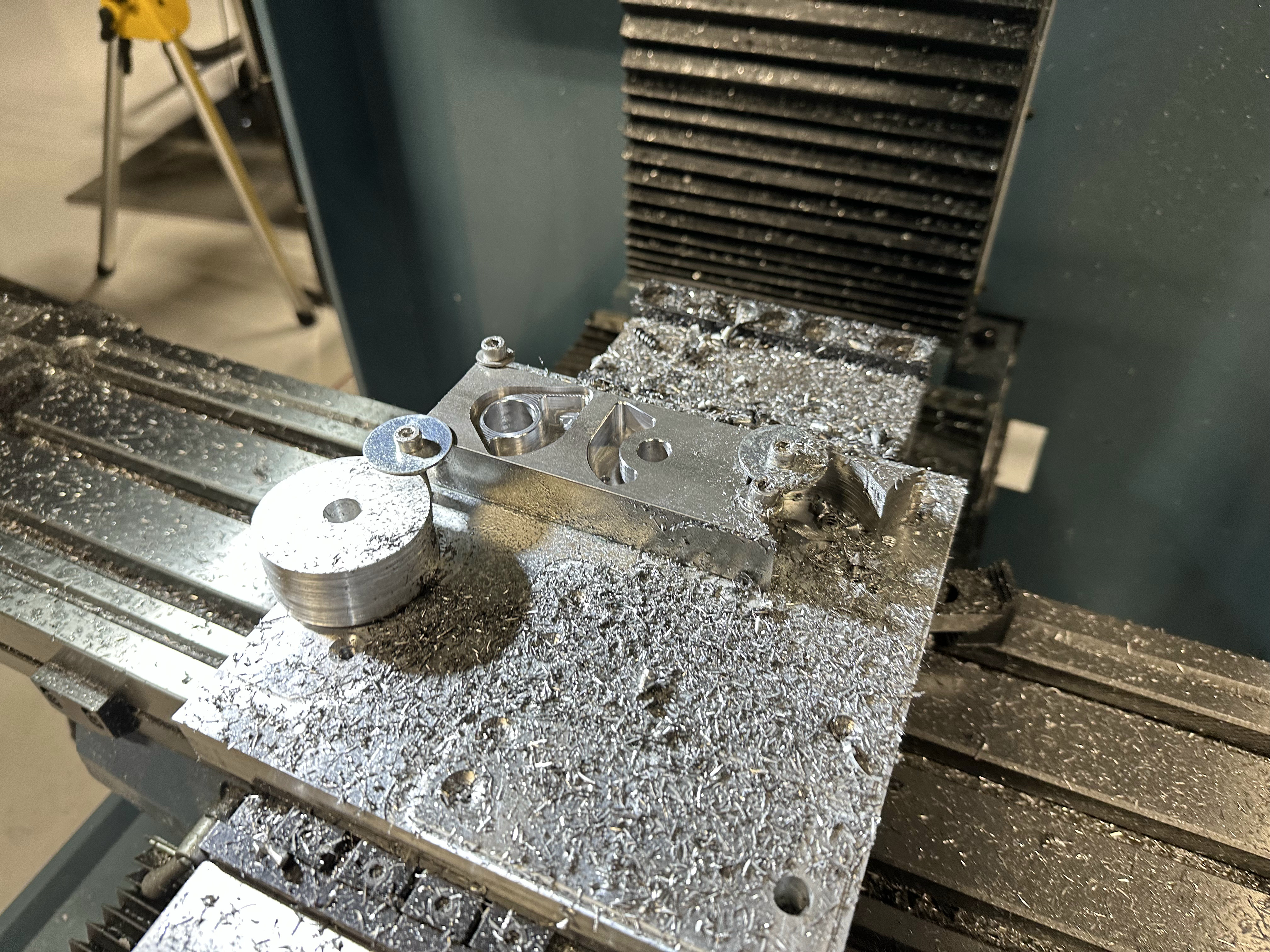
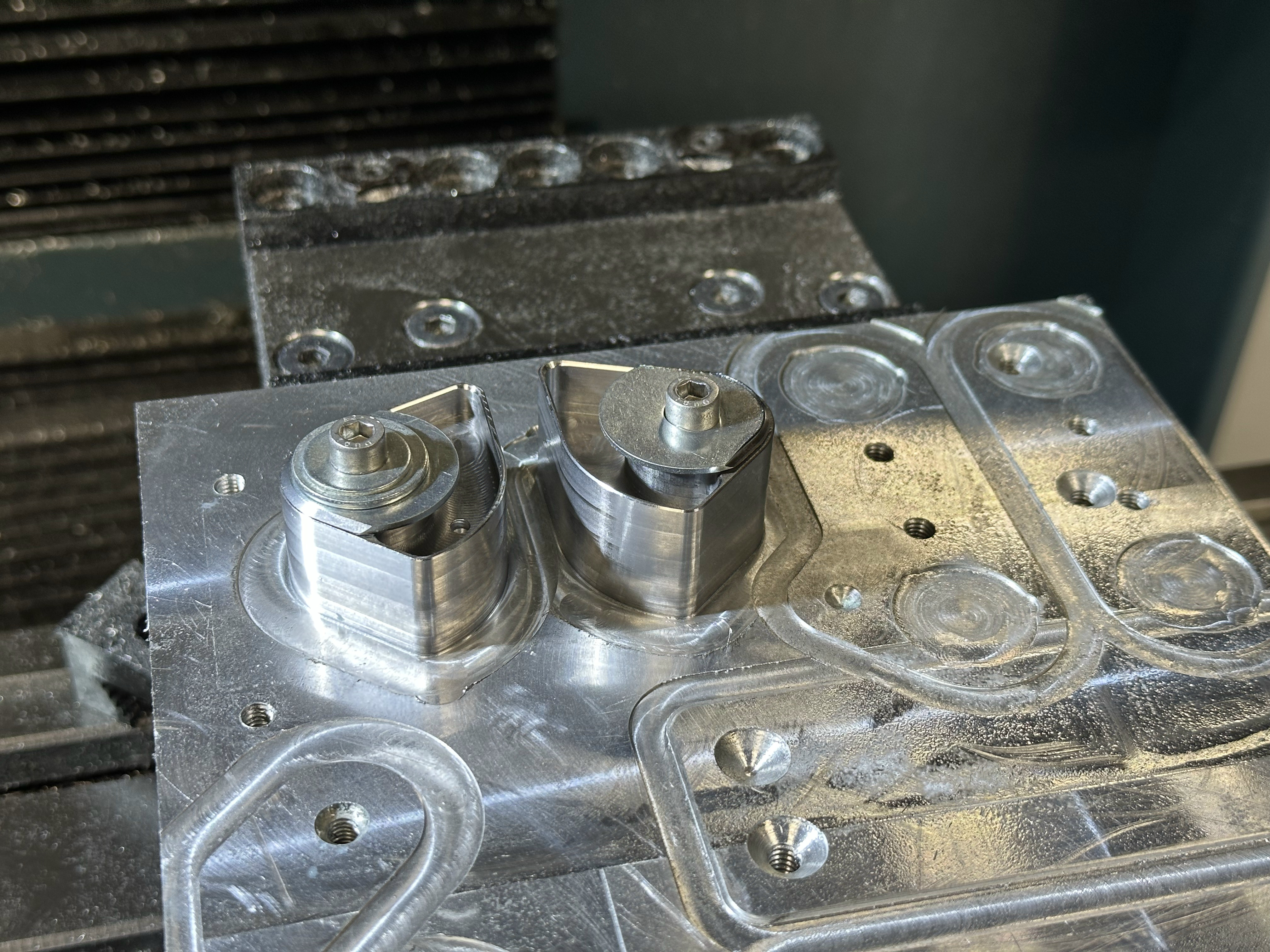
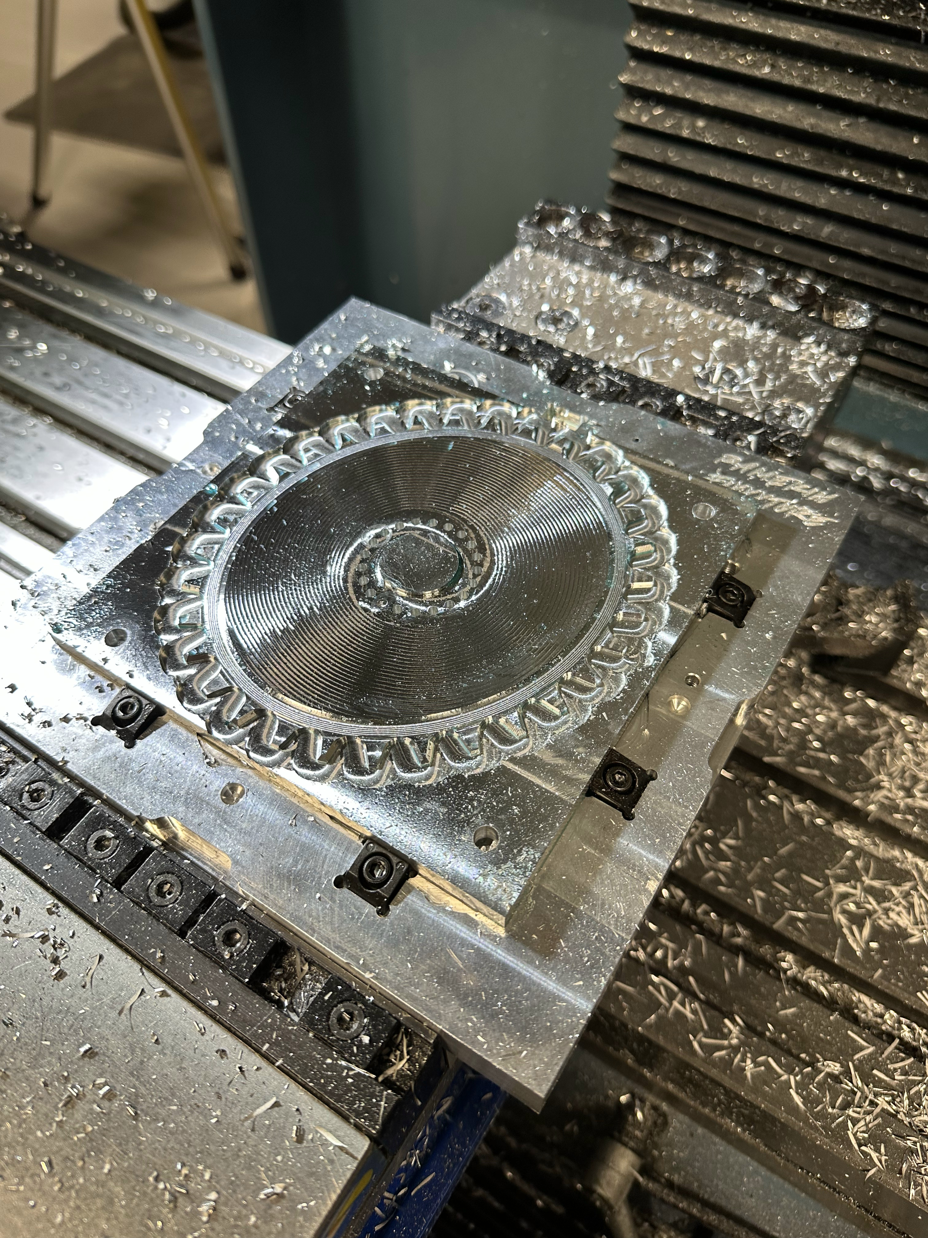
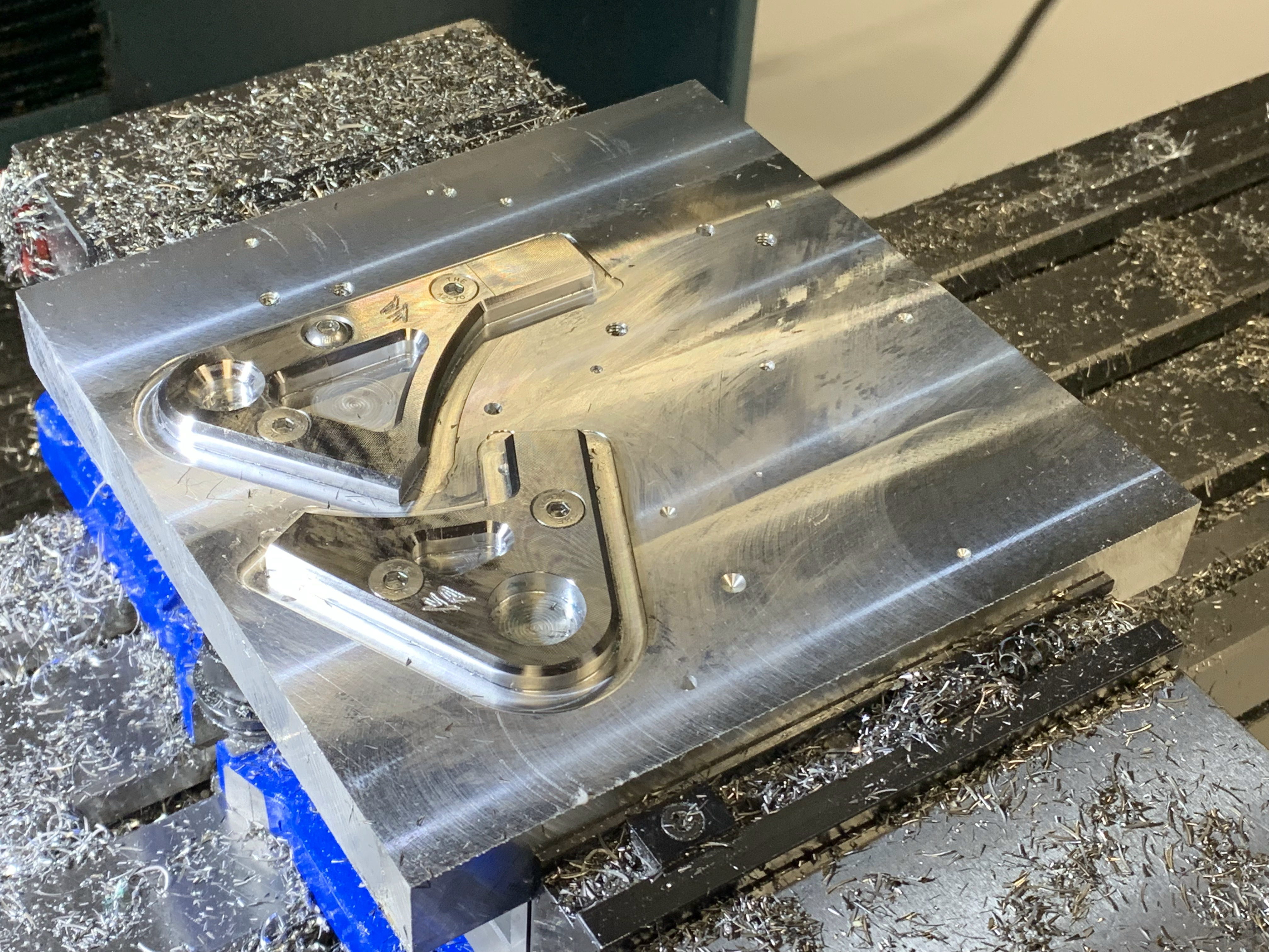
Machining bending dies for 3/4" tubing out of 1" x 2" x 4" 6061 Al. Plan was to use a similar bending process with an arbor press as seen in Paul Brodie’s legendary YouTube videos.
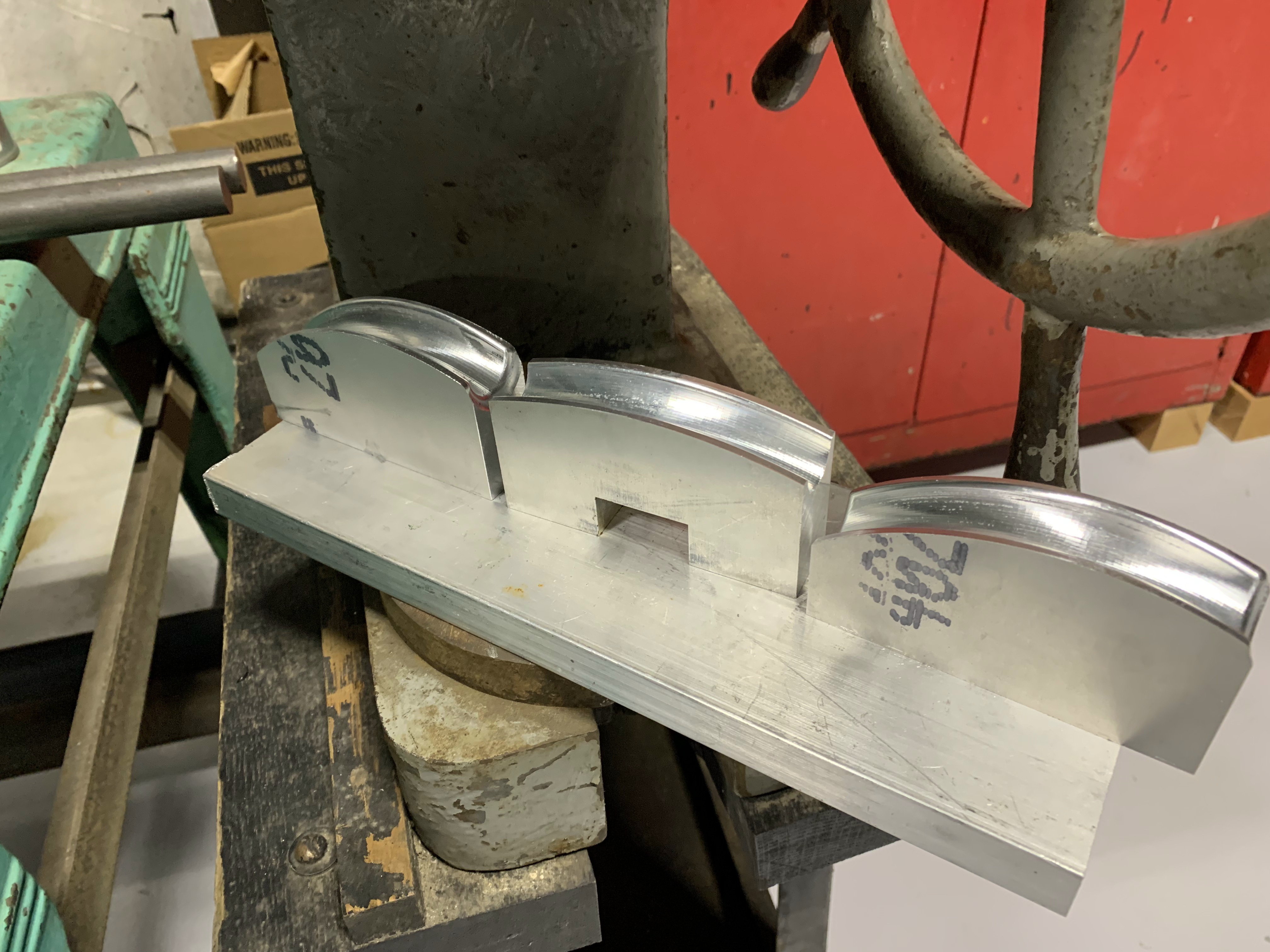
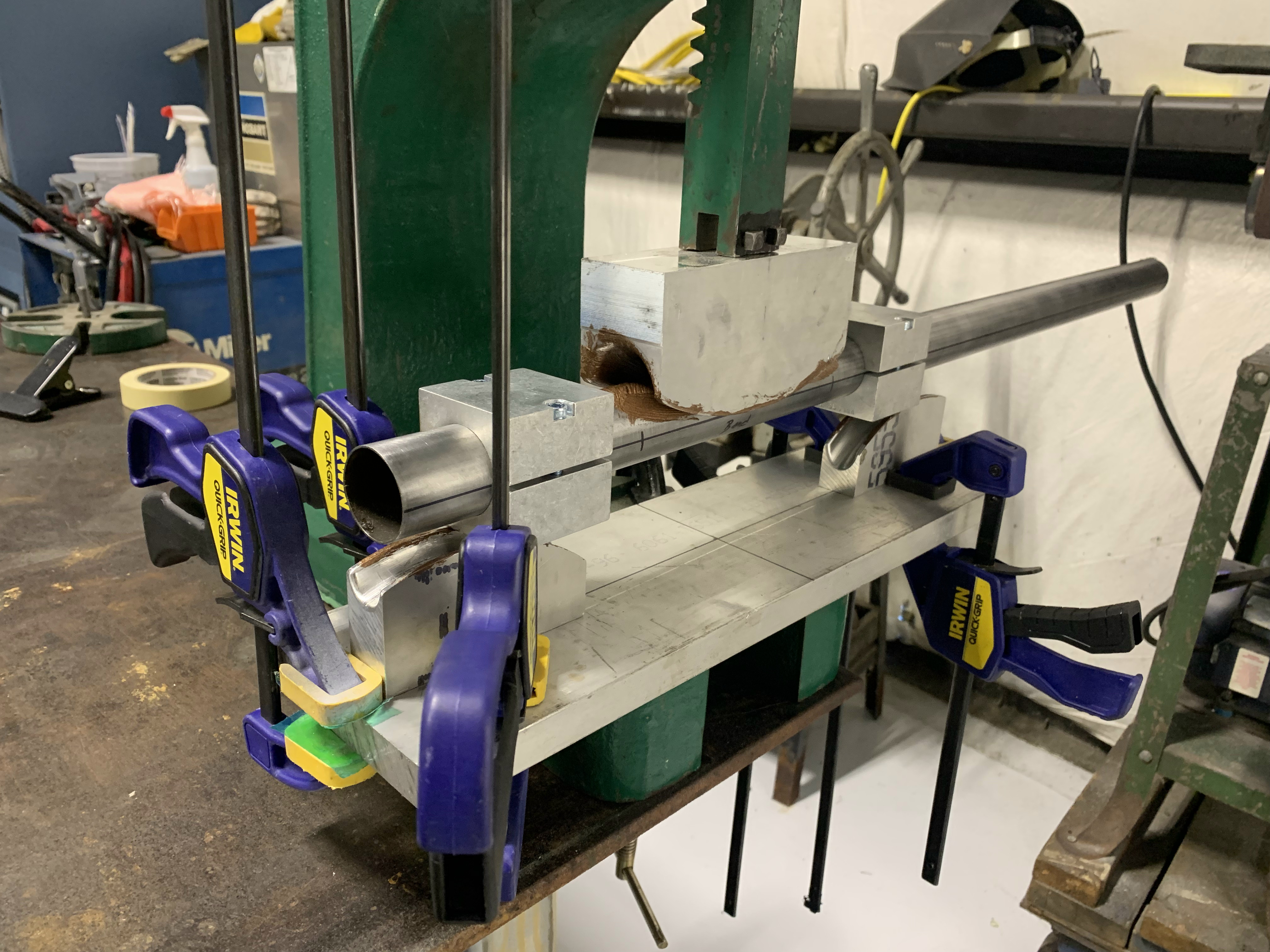
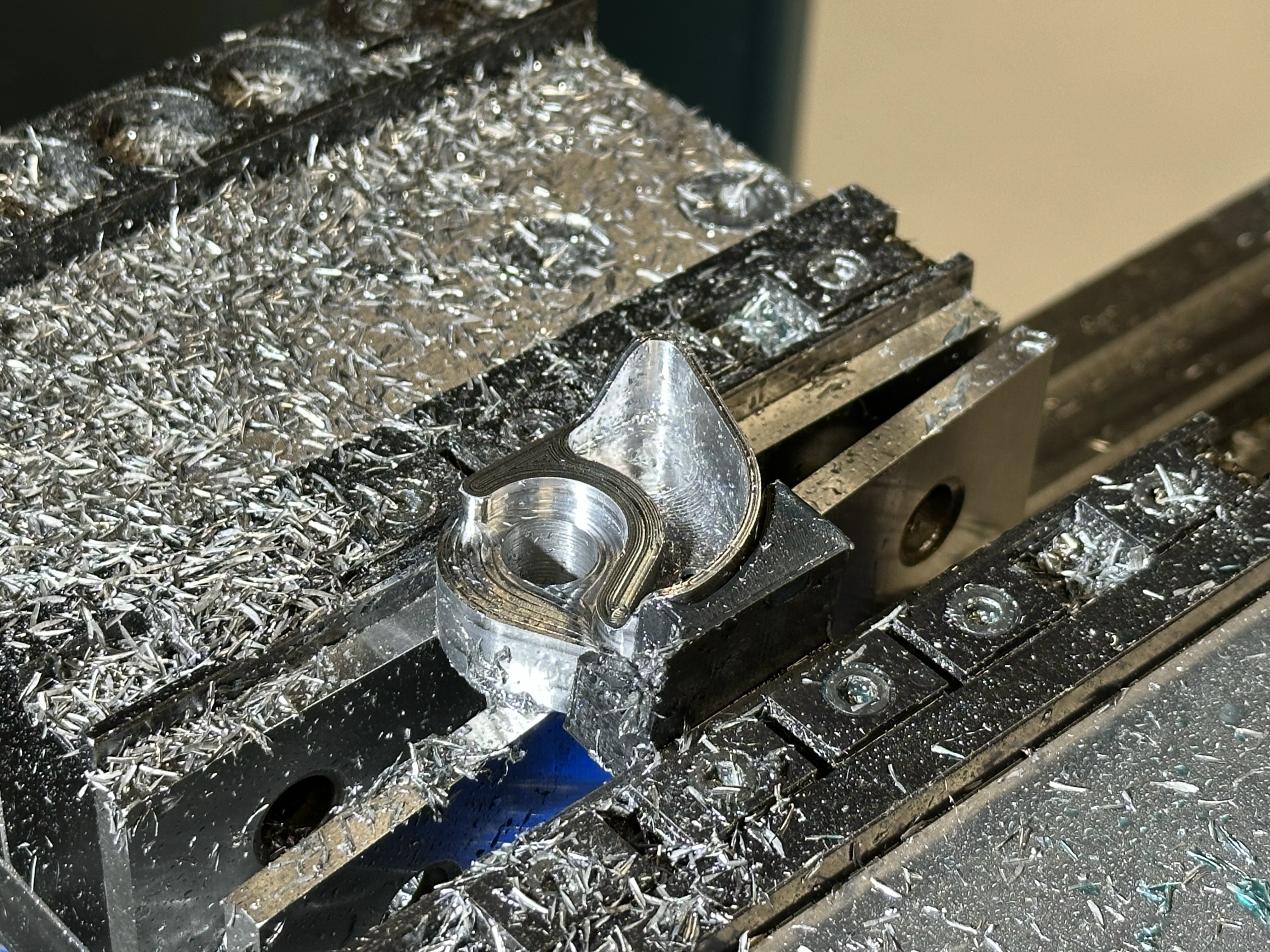
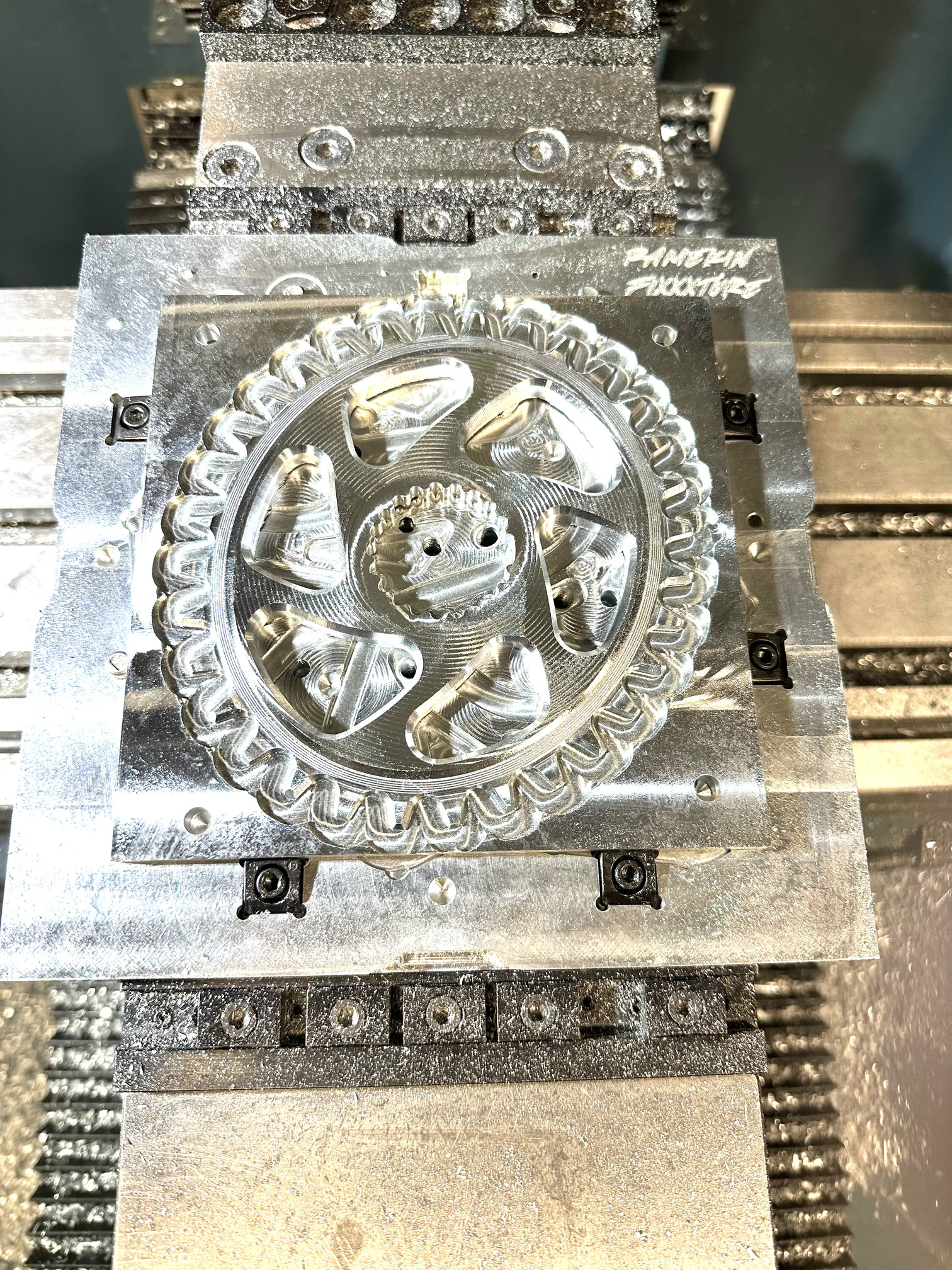
I apparently didn’t get any good images of the bending process, but here are the three dies required for bending. The center die would be inverted in practice and fixed to the head of the arbor press. Hopefully you get the idea.
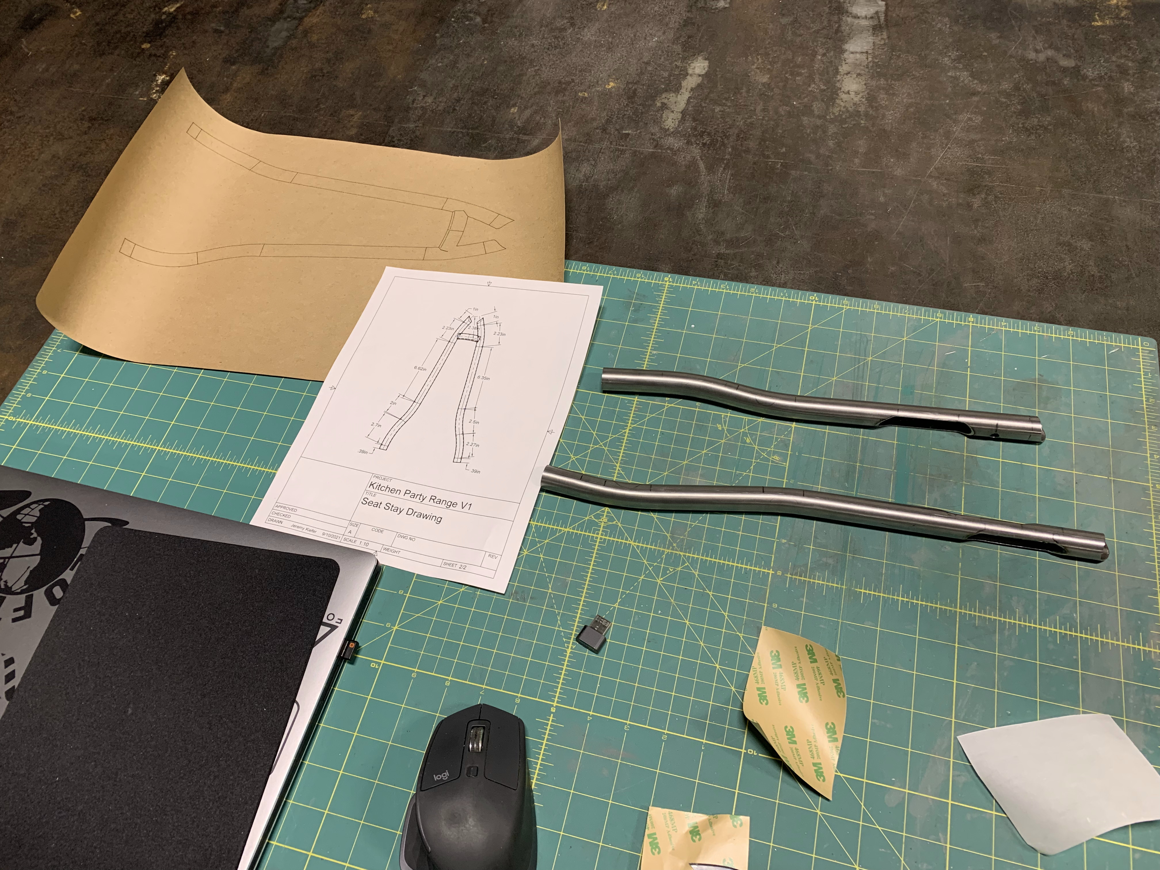
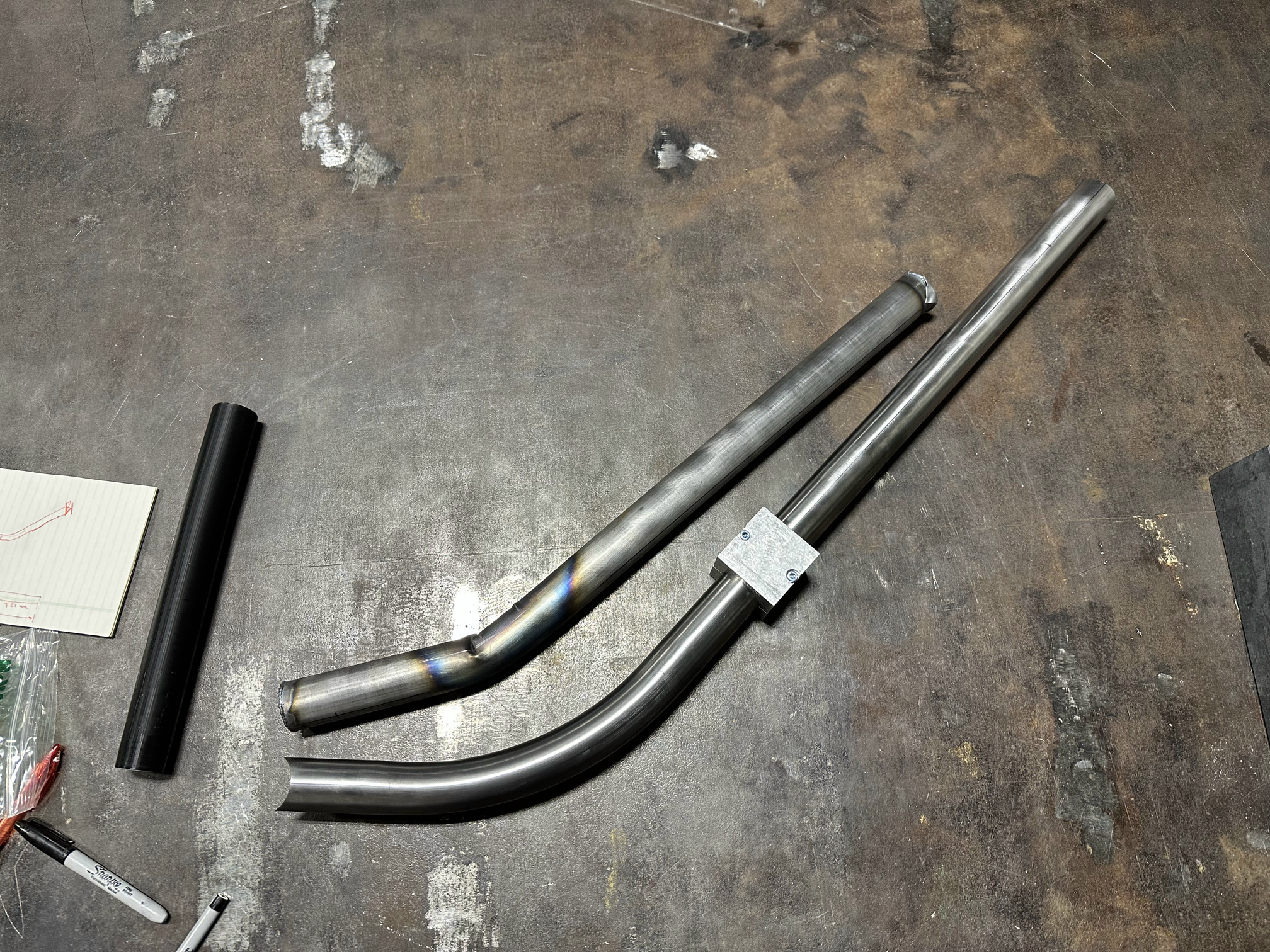
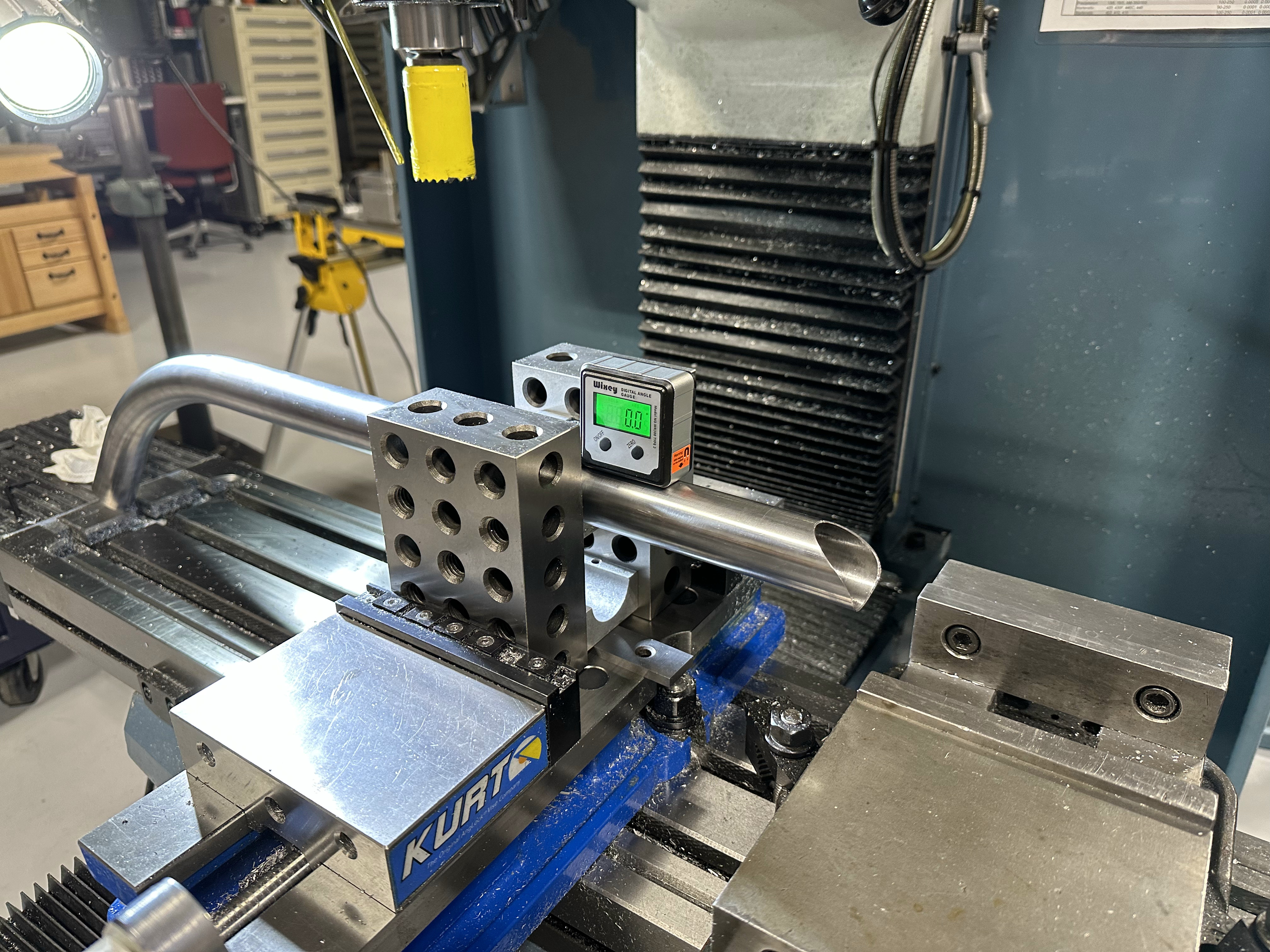
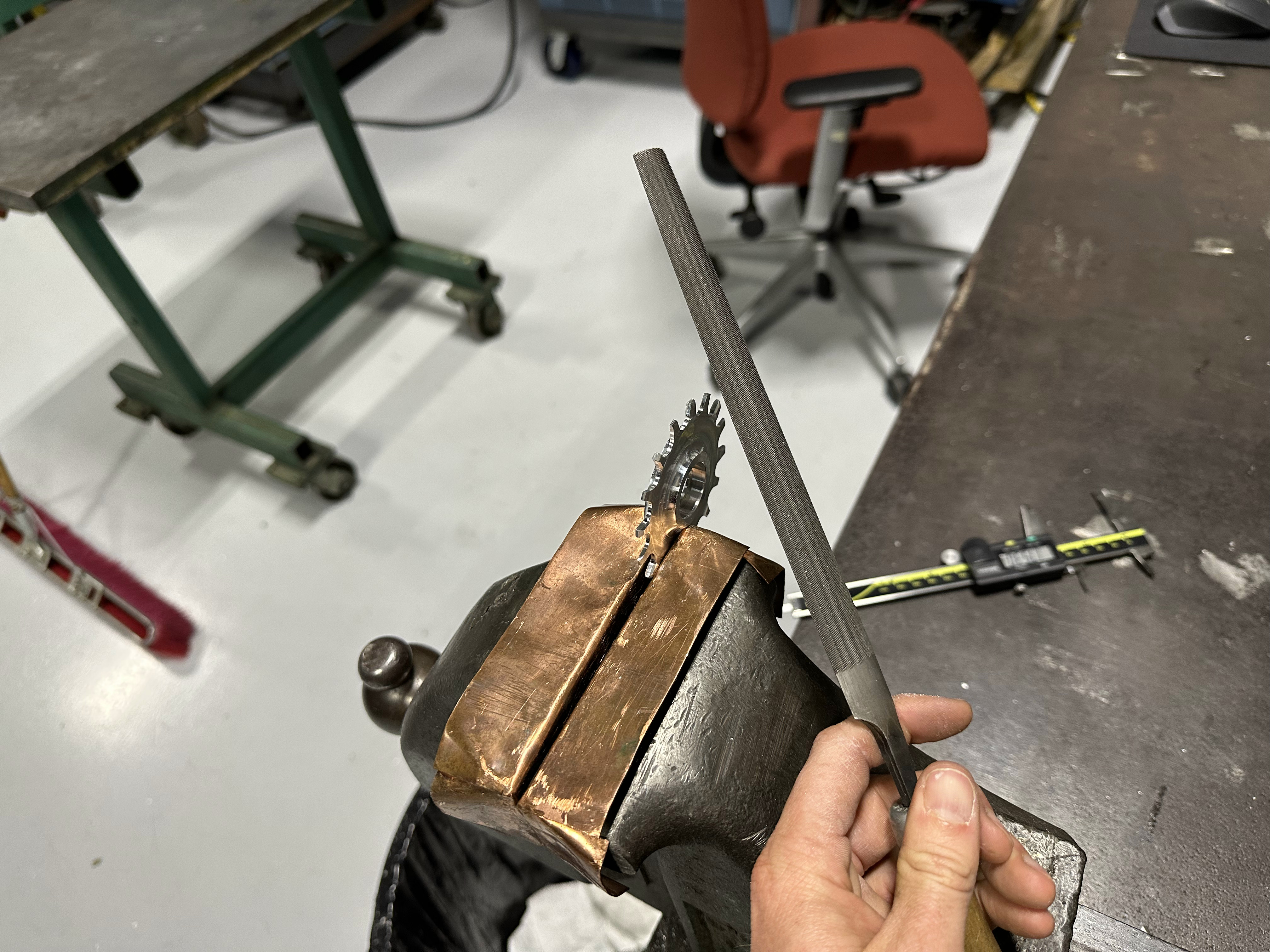
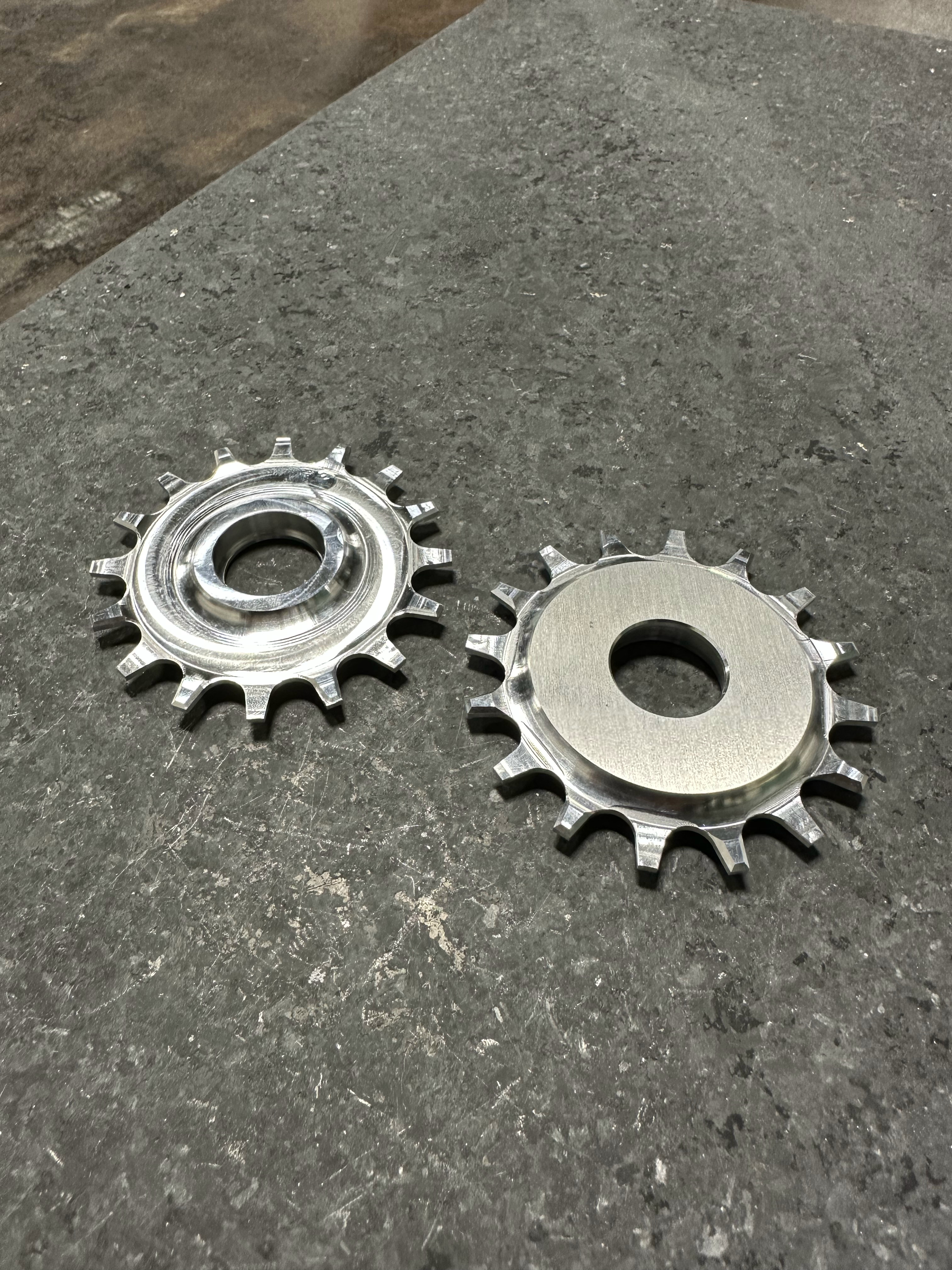
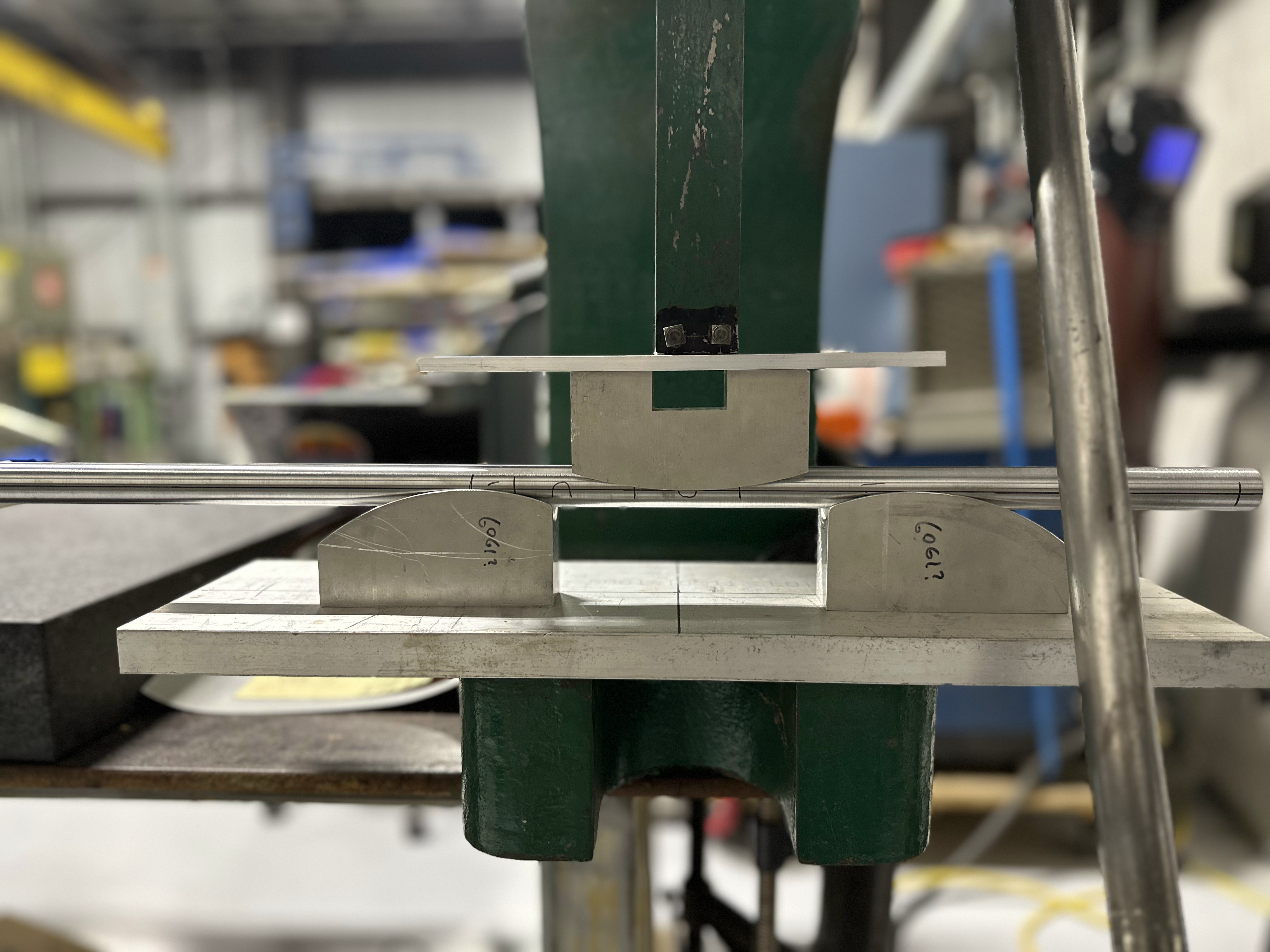
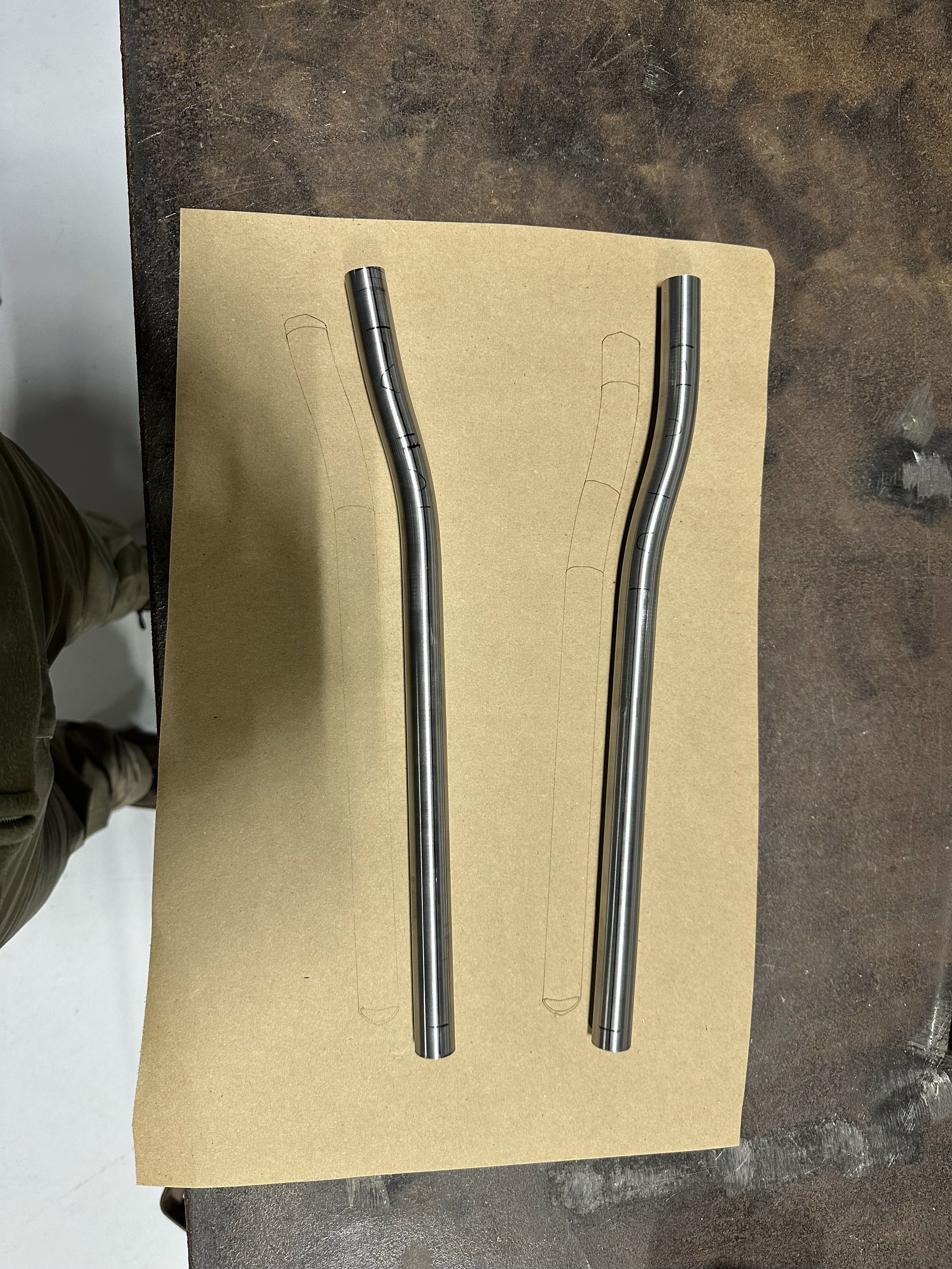
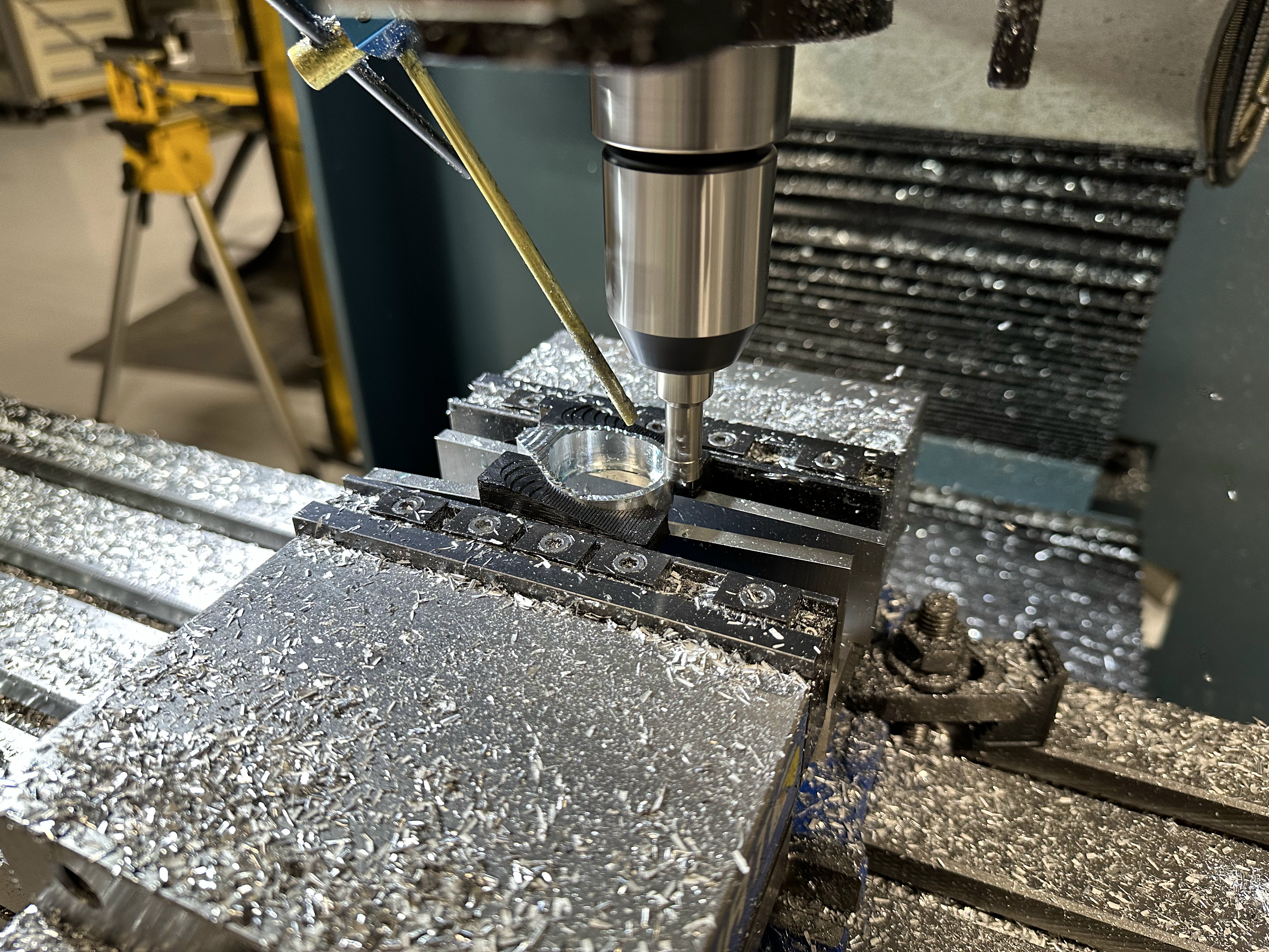
Created a 2D drawing with bending distances for reference and drew out a 1:1 scale in-plane bent tube sketch on our 2-axis fabric cutter (pen tool). I bent the tubes until they looked good overlaid on the full scale drawing. Then milled out pockets for tire and chainring clearance.
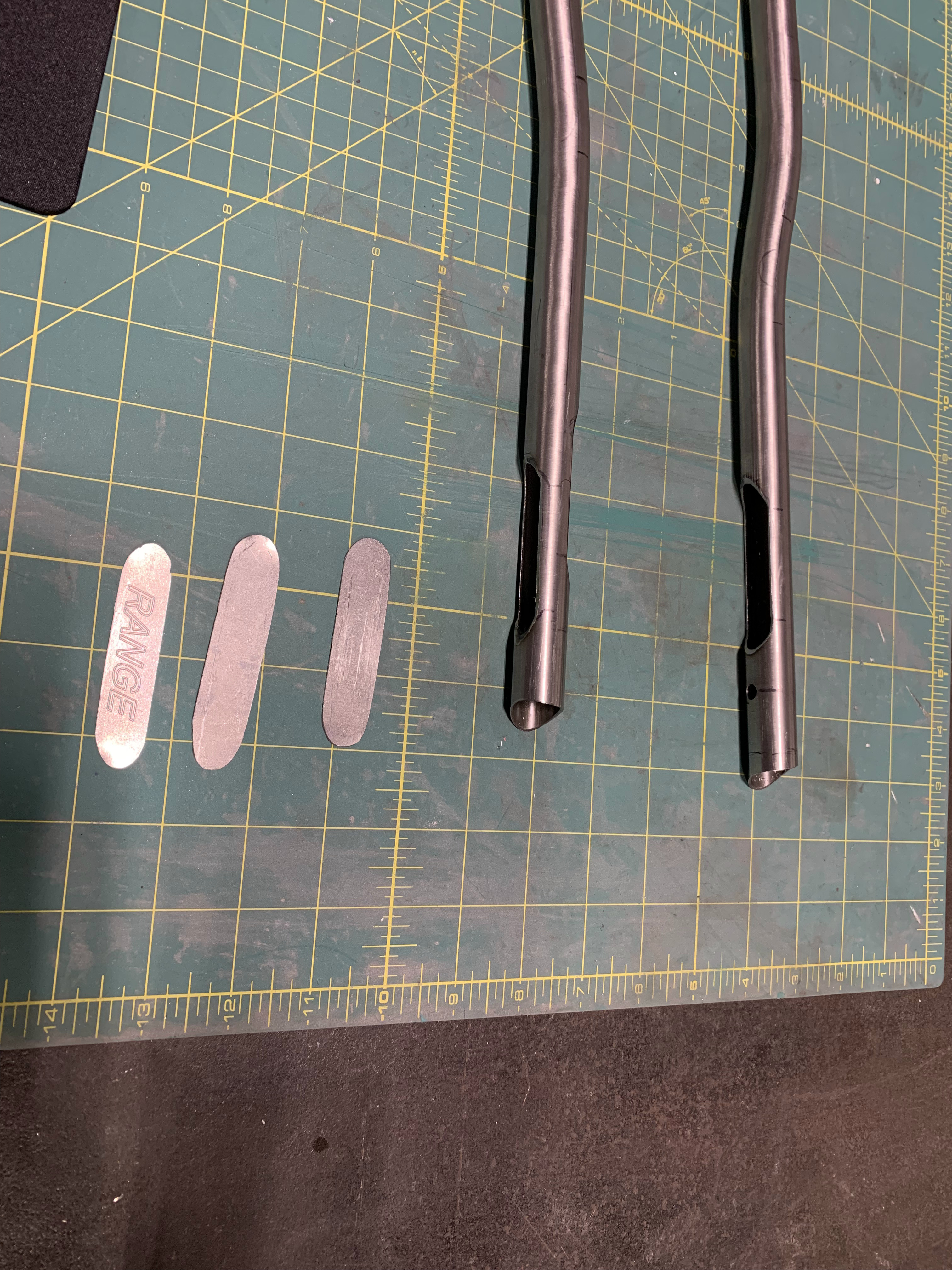
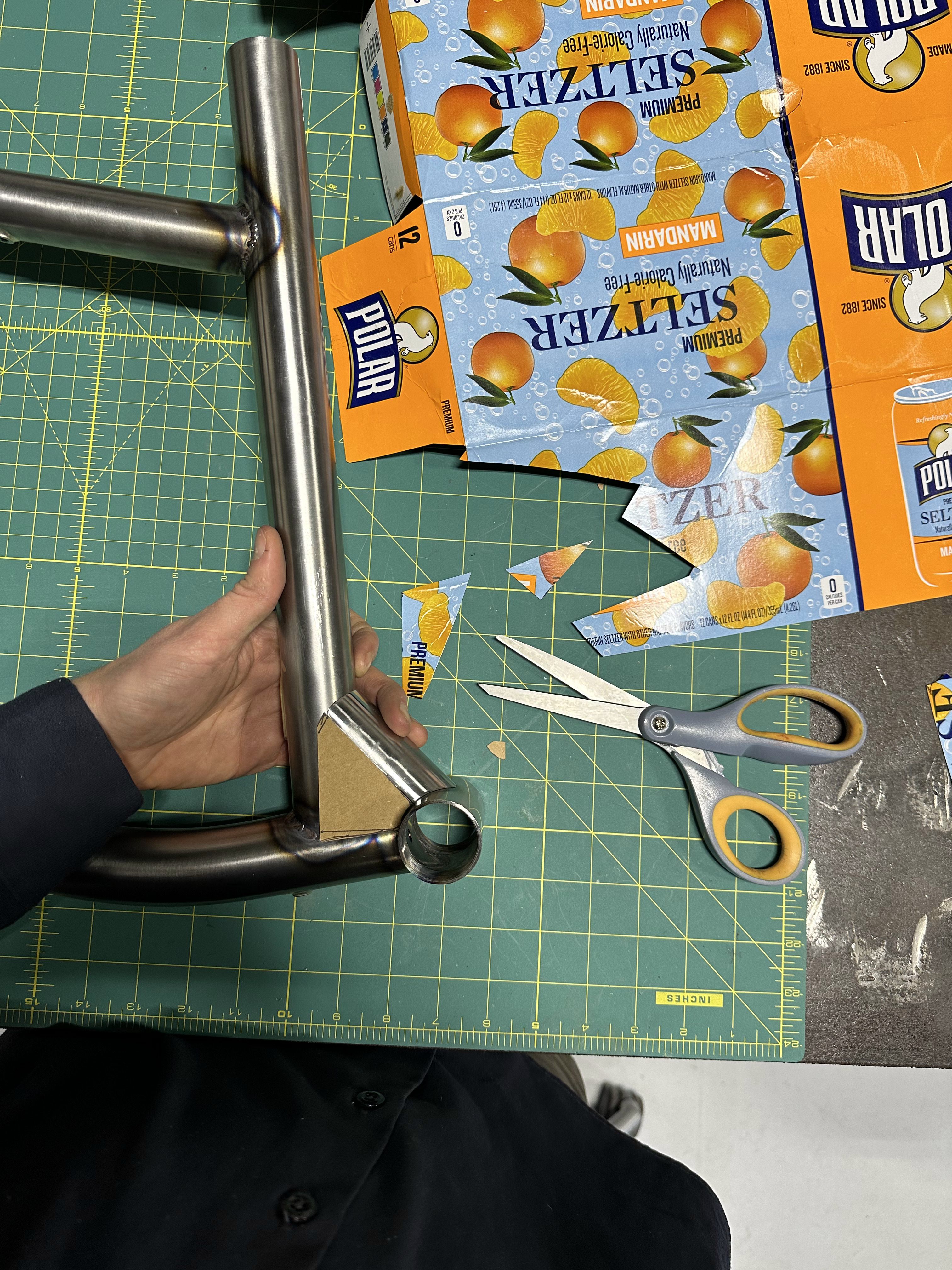
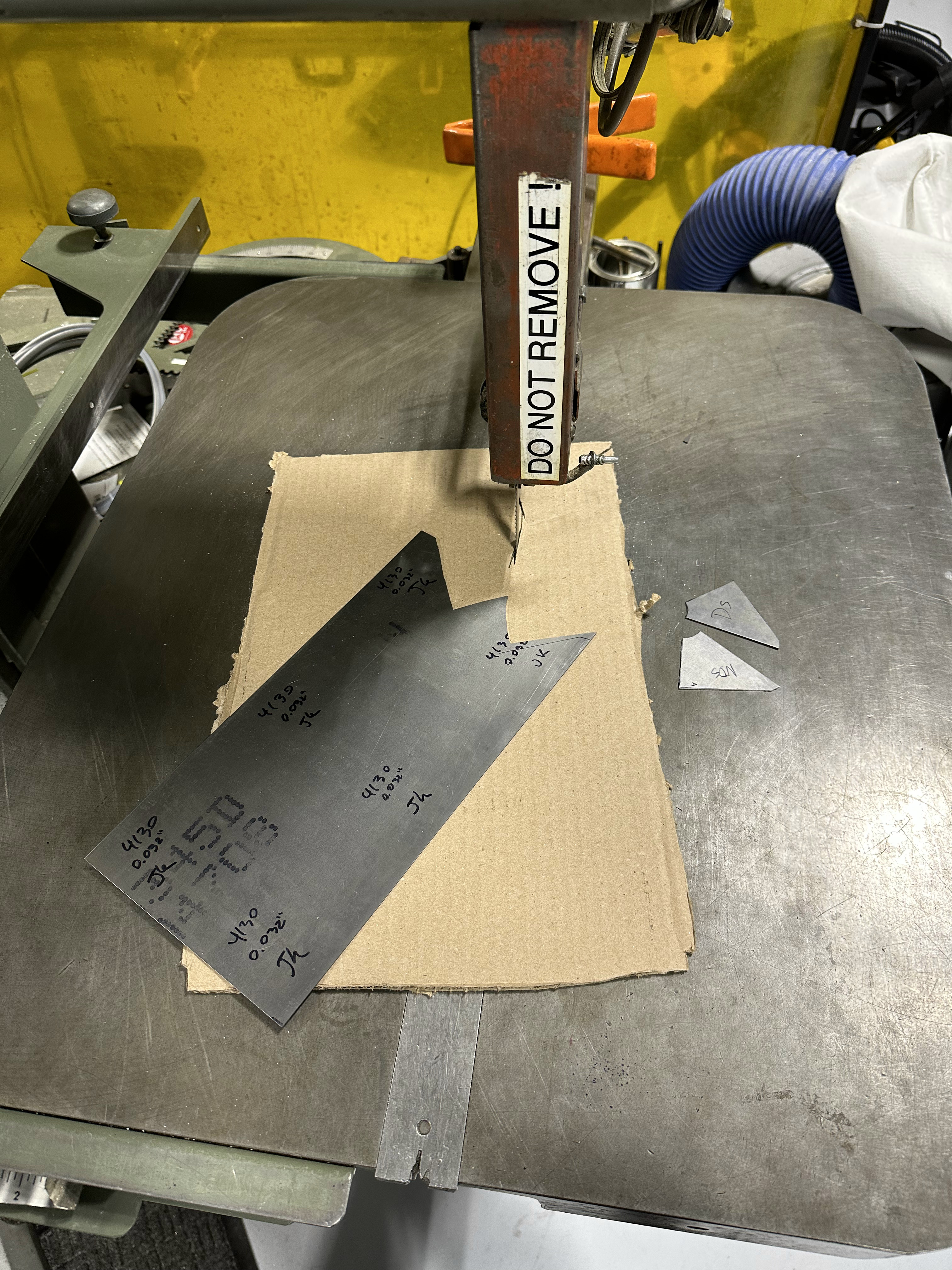
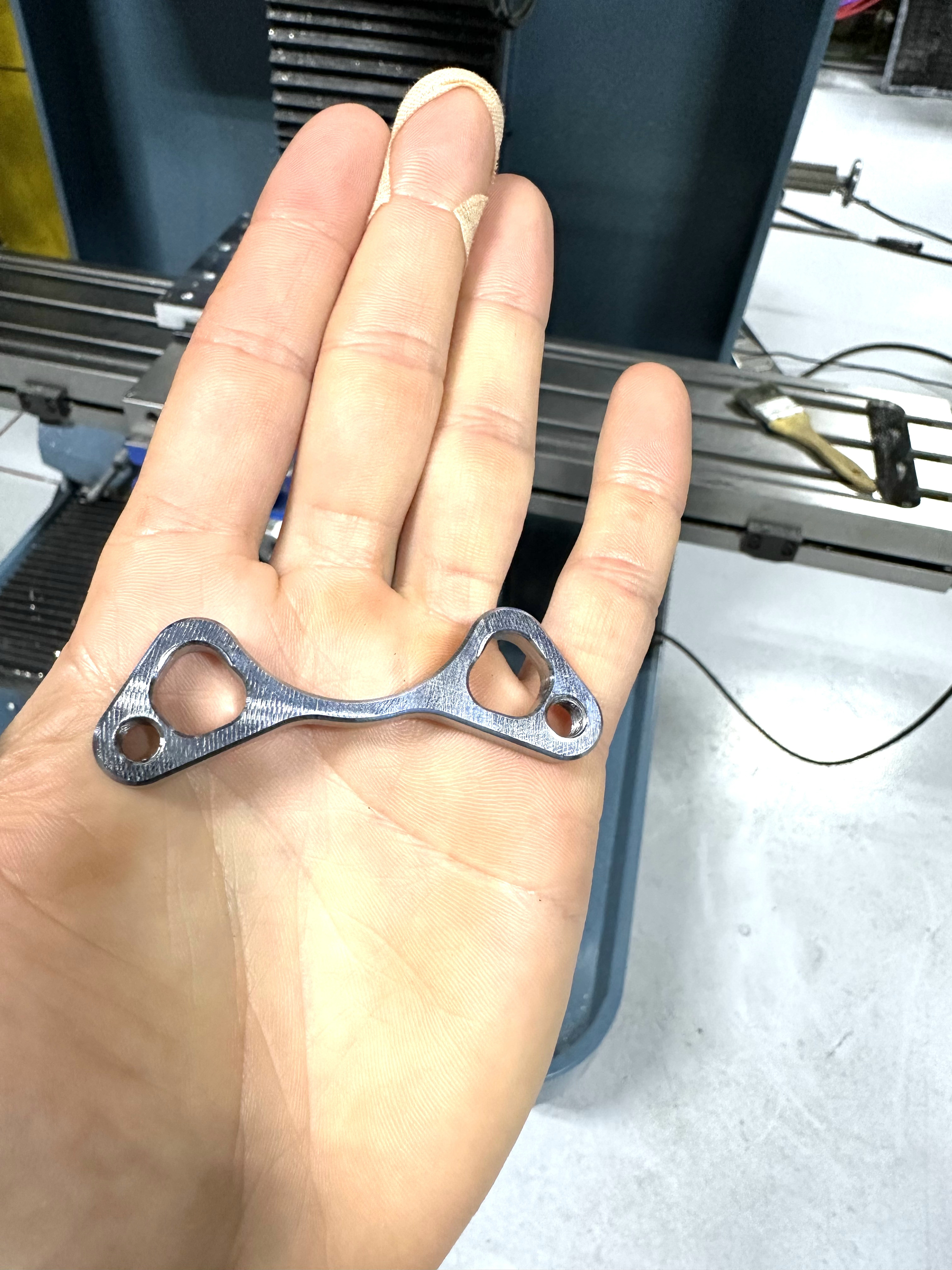
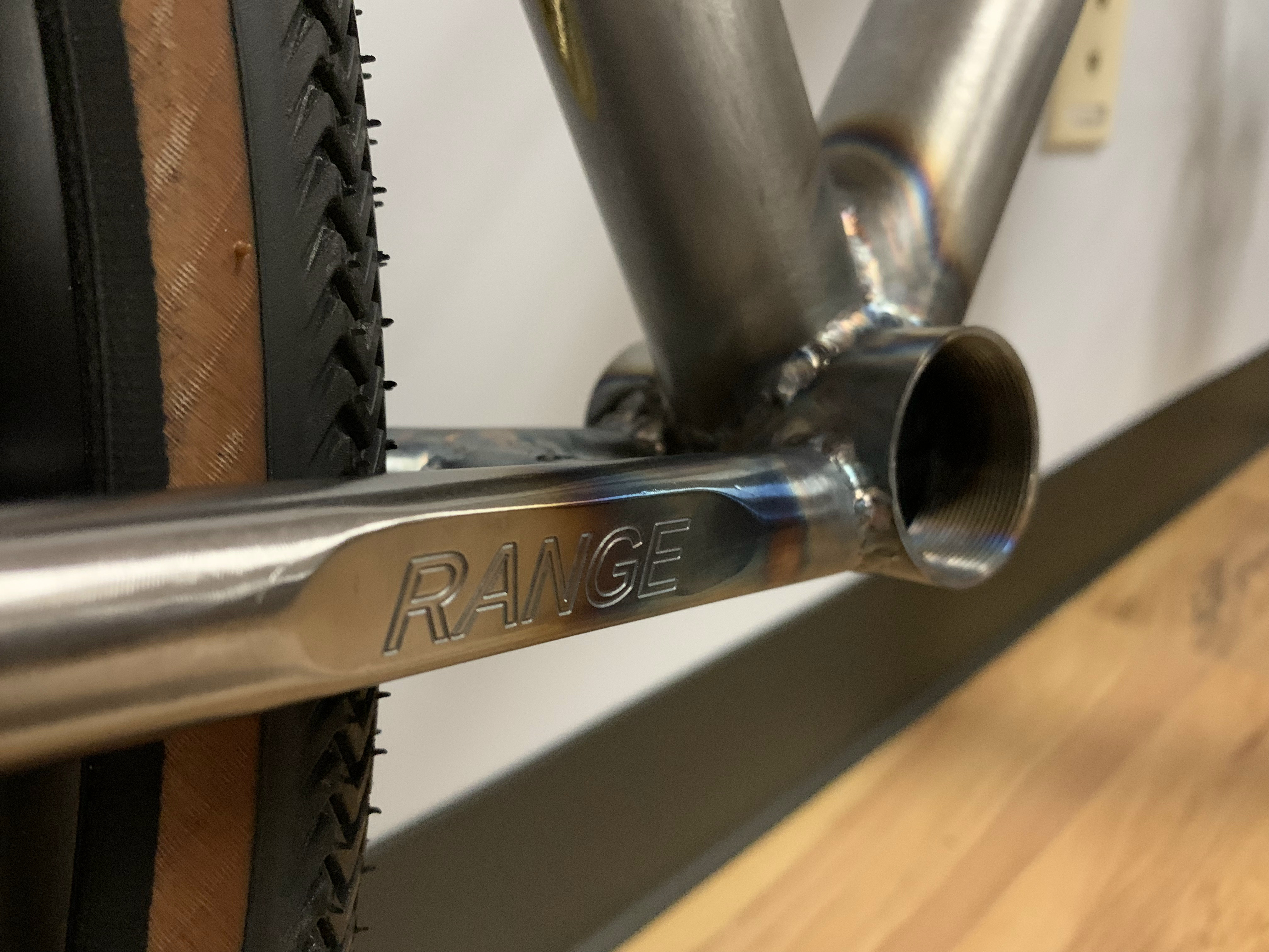
I cut out three patches from 0.032 4130 plate and engraved the model name “RANGE” on the chainstay clearance patch. These patches were shaped by the Paul Brodie inspired “cardboard aided design” method. Once the patches were welded on, they were ground and sanded down to produce smooth contours.
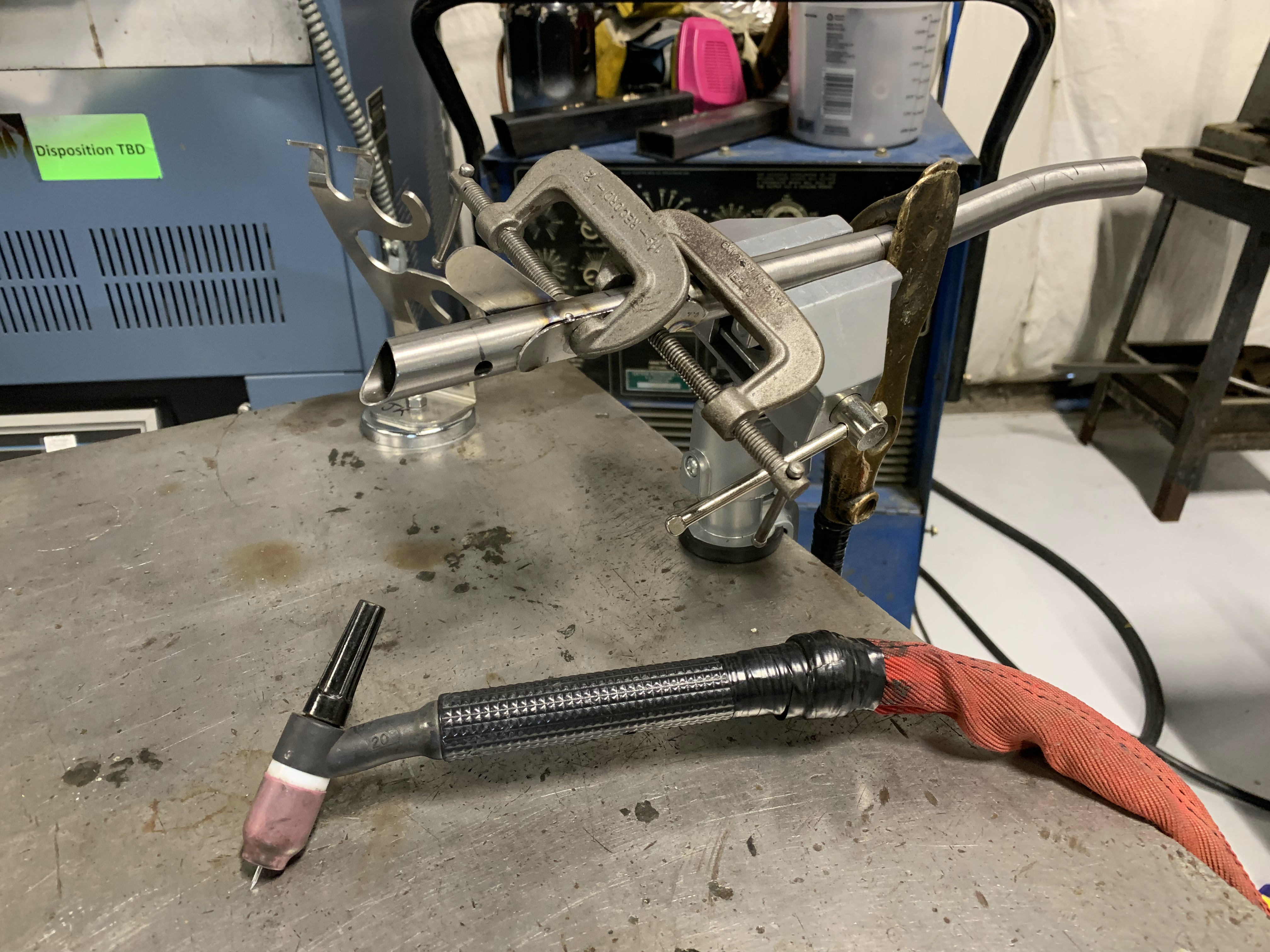
Creative fixturing to hold the patches in place for tack welding.
Similar method was used to create these contours for the rear dropouts. They didn’t work out as well. They were rushed as I was growing impatient. This lead to poorly fitting slots for the rear dropout plates. This caused an issue when the novice welder was trying to fill a 1/8" gap between 0.25" plate and 0.035"WT tubing…
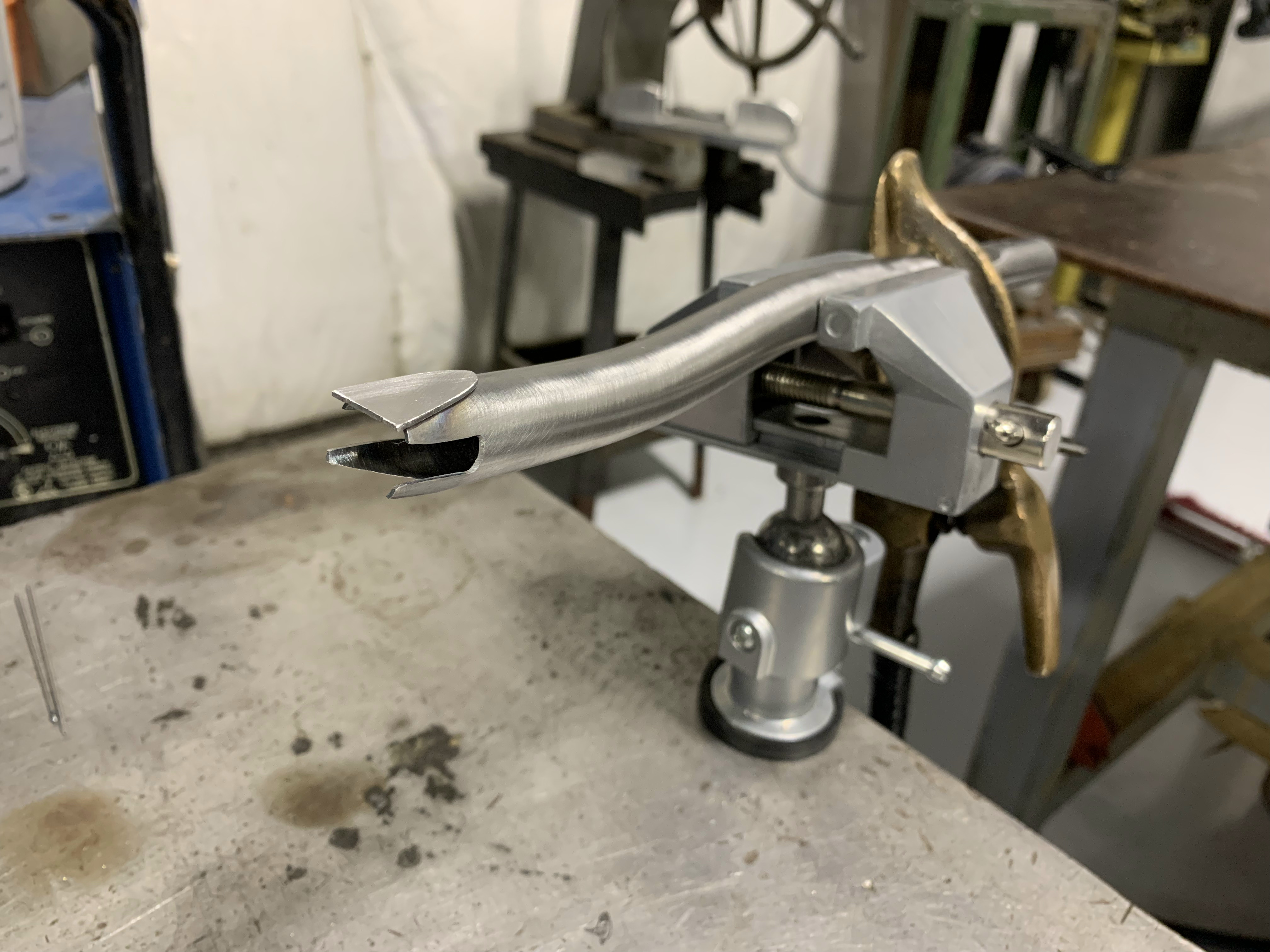
The clearance plates came out pretty great!, And yes, I definitely overcooked the welds.
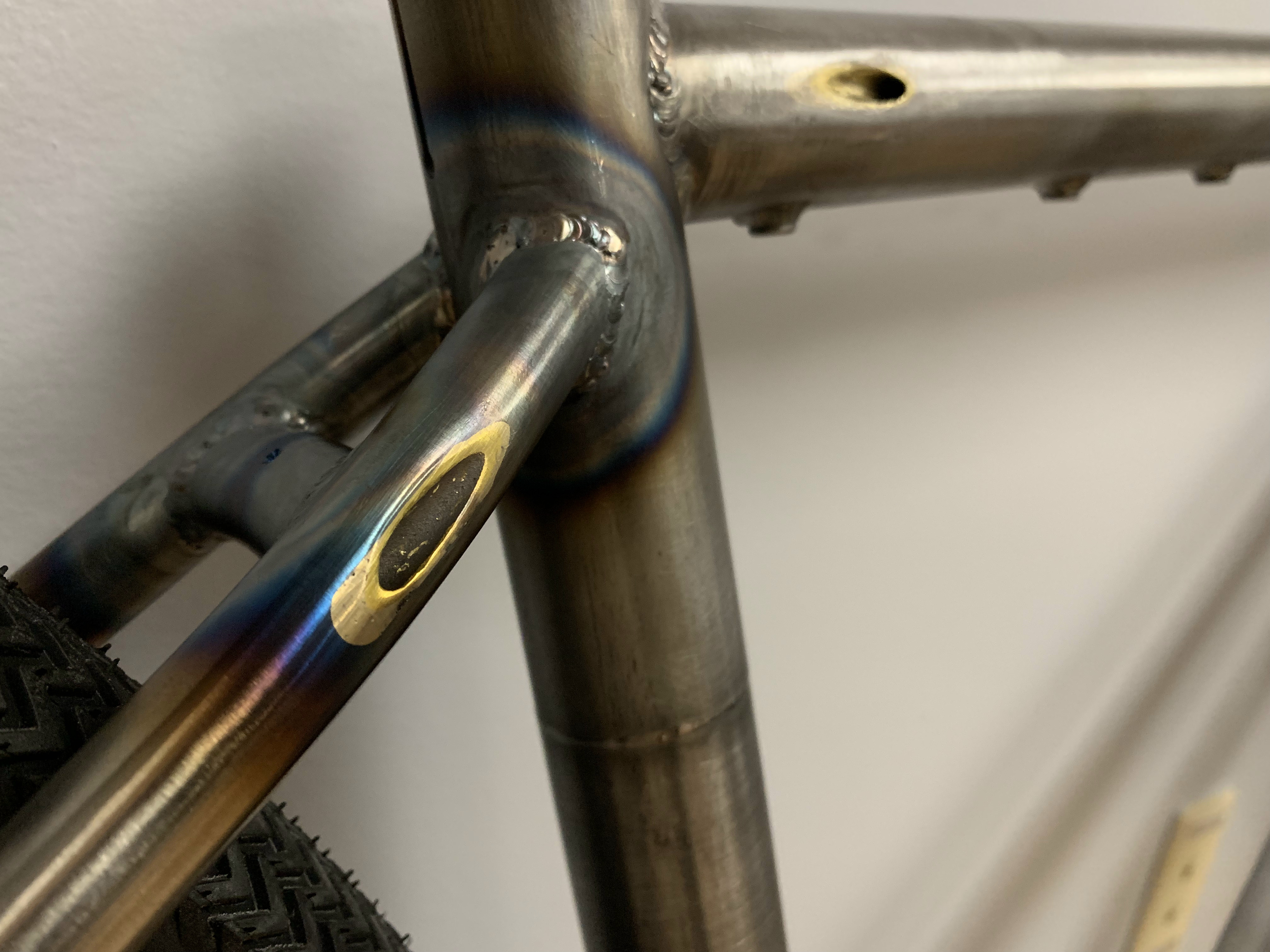
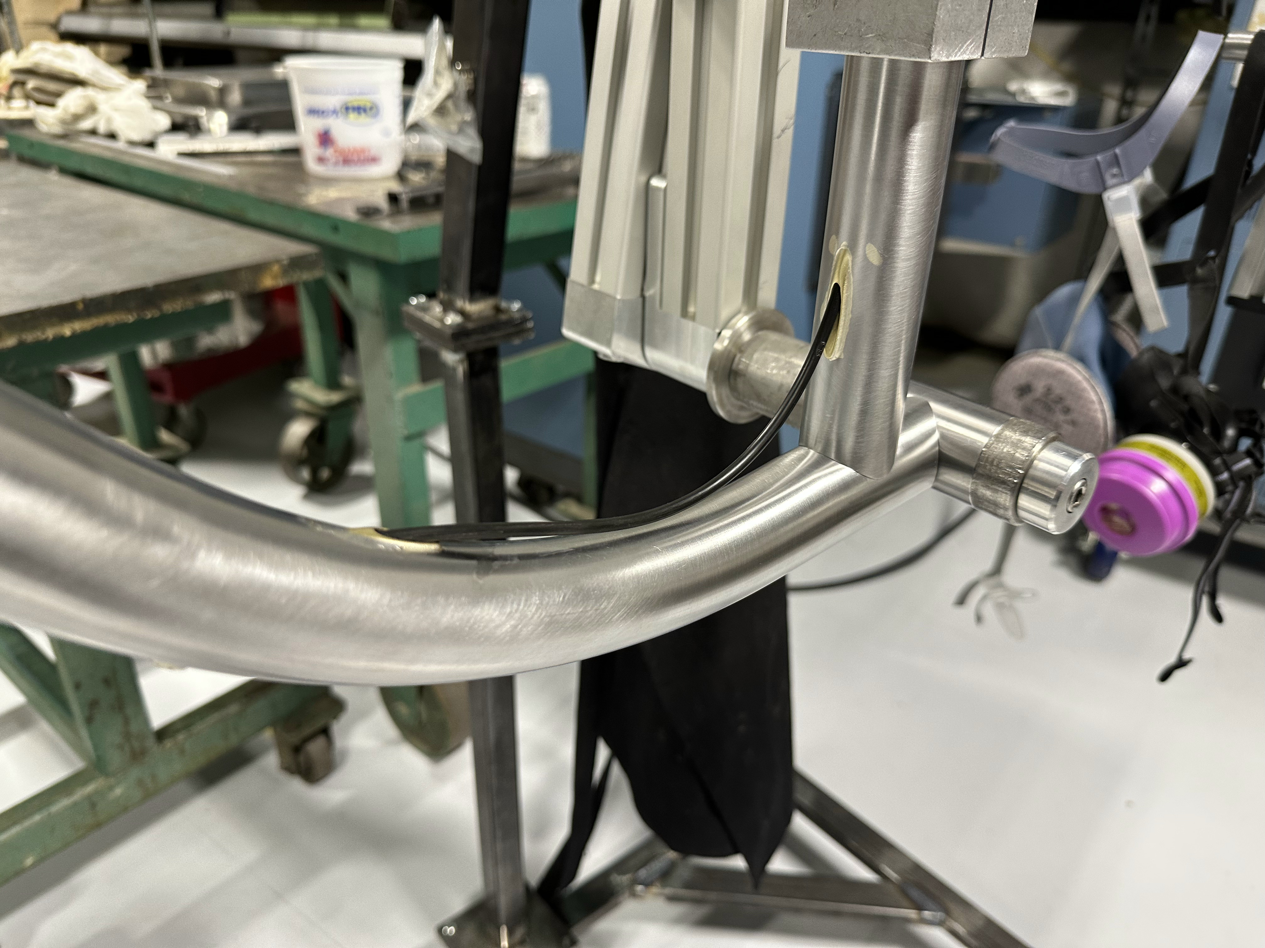
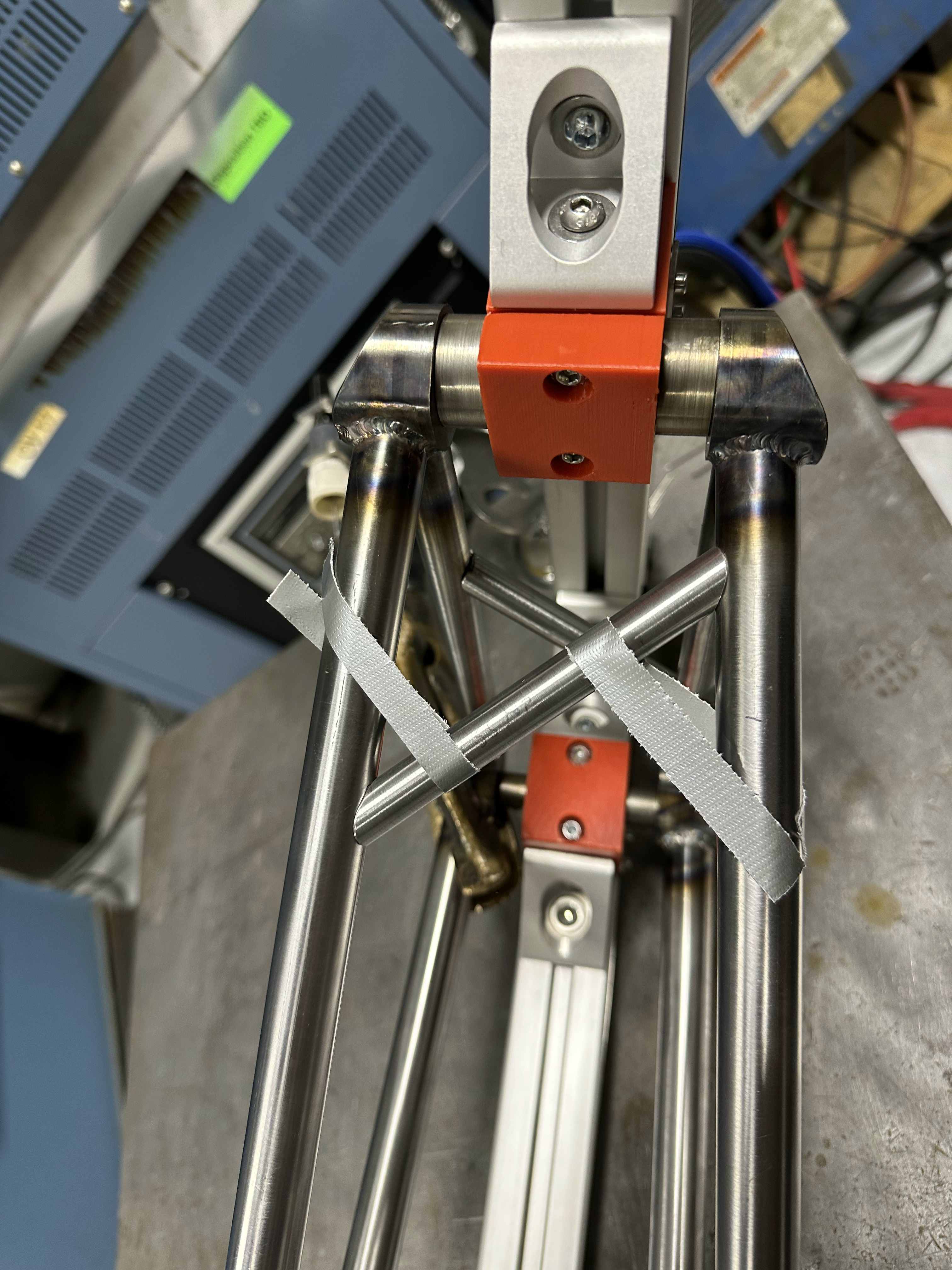
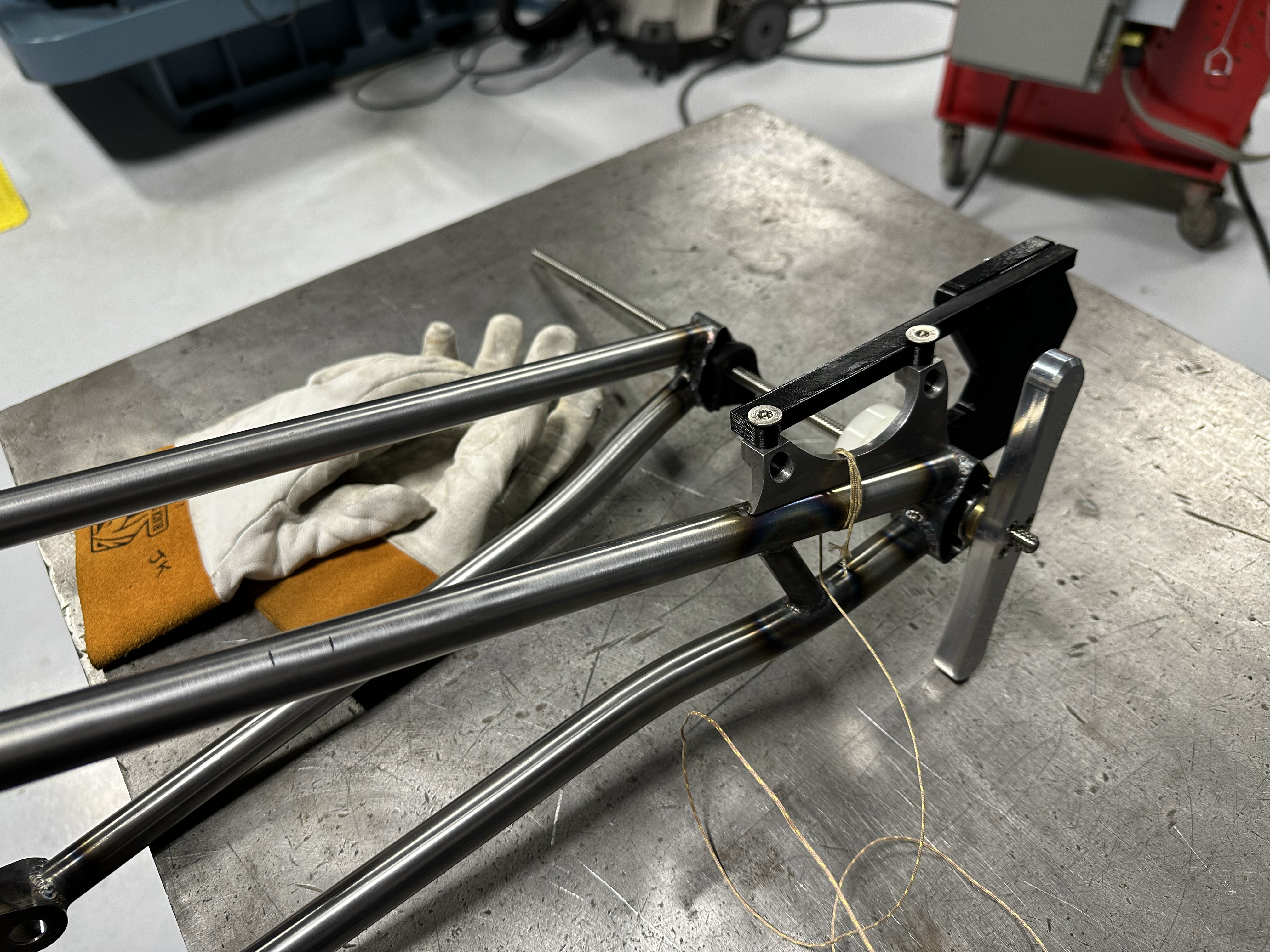
Jumping a bit ahead here, but I also brazed in some brass tubing in the seat stays for the rear shifting line. I wasn’t able to insert the bent brass tube into the bent seat stays. I also wasn’t able to bend seat stays with the tubing already inserted. How do people typically do this with bent tubes? I ended up bending the tube, cutting the slots, cutting the drive side seat stay in half, inserting the bent brass tube, welding the tube back together, grinding and sanding the tubing flush with the outer surface. I can’t believe it hasn’t broken yet.
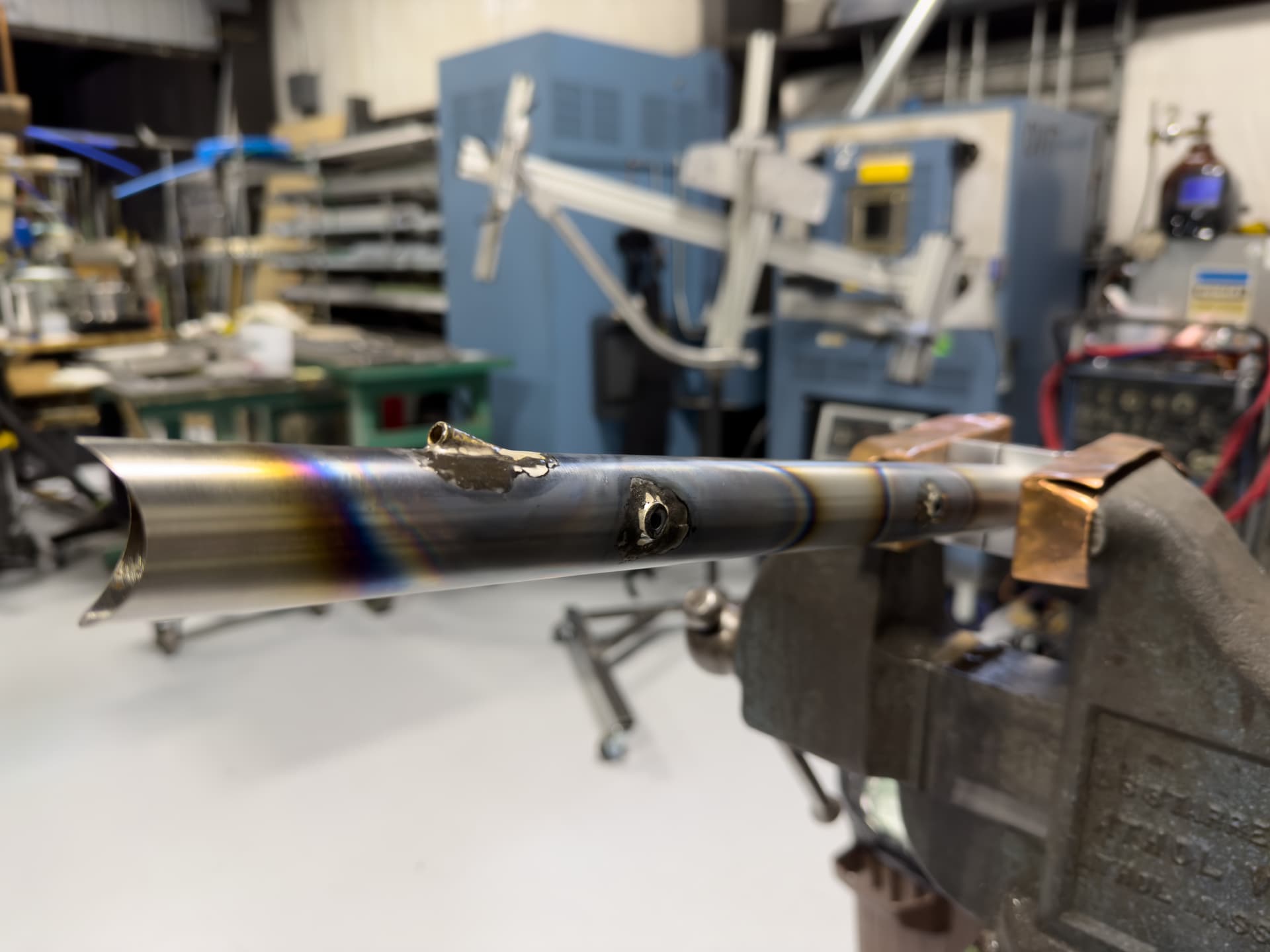
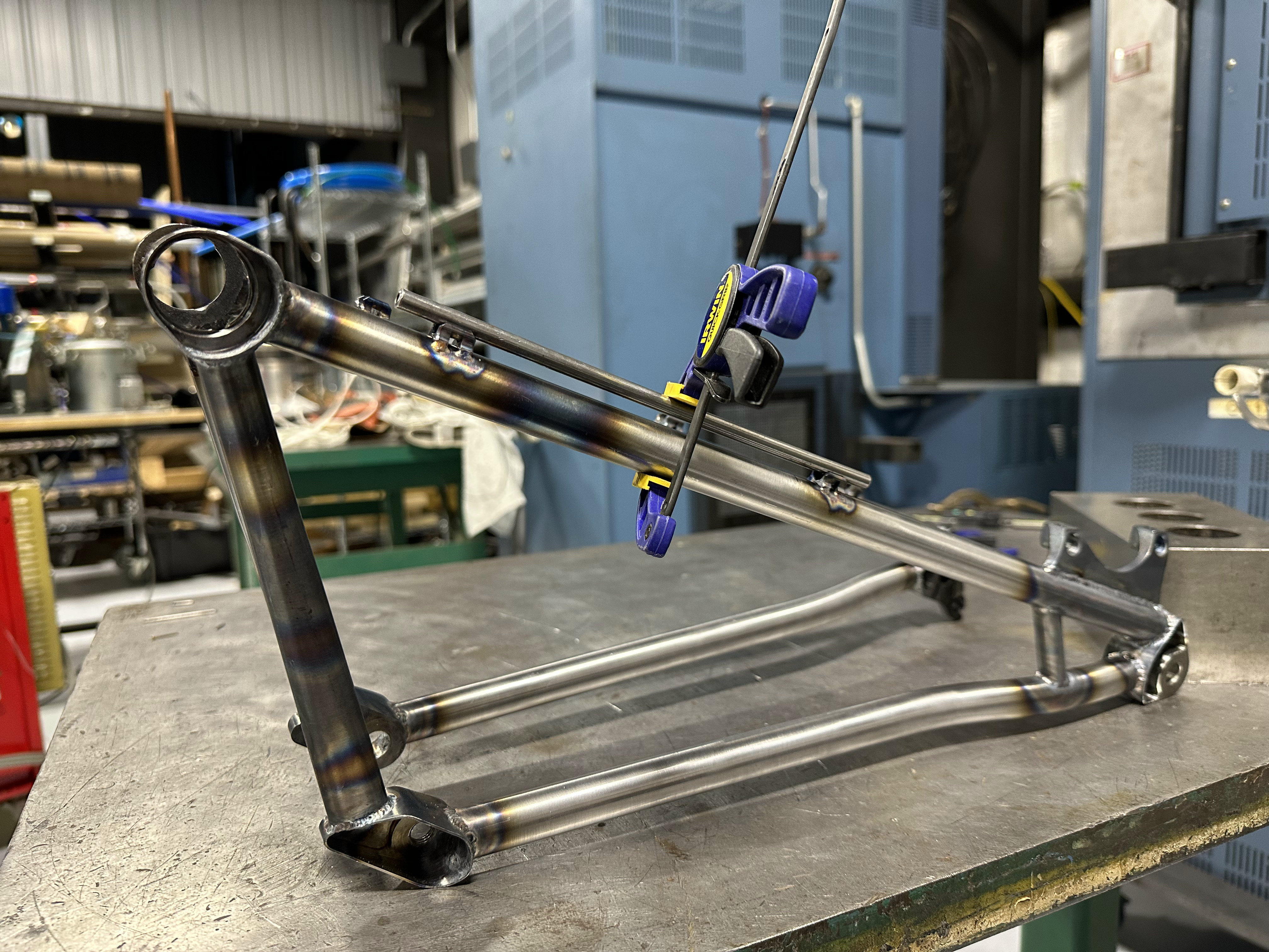
This is another place where I realized I really fucked up. This whole time I had it in my mind that the rear brake cable routing was similar to mtb routing where it would make sense to run down the seat stay. whoops. I was too far in the process to make any changes, but luckily hadn’t inserted the internal tubing on the non-drive side yet.
I shamefully got creative.
Finished welding and test fit in the office.

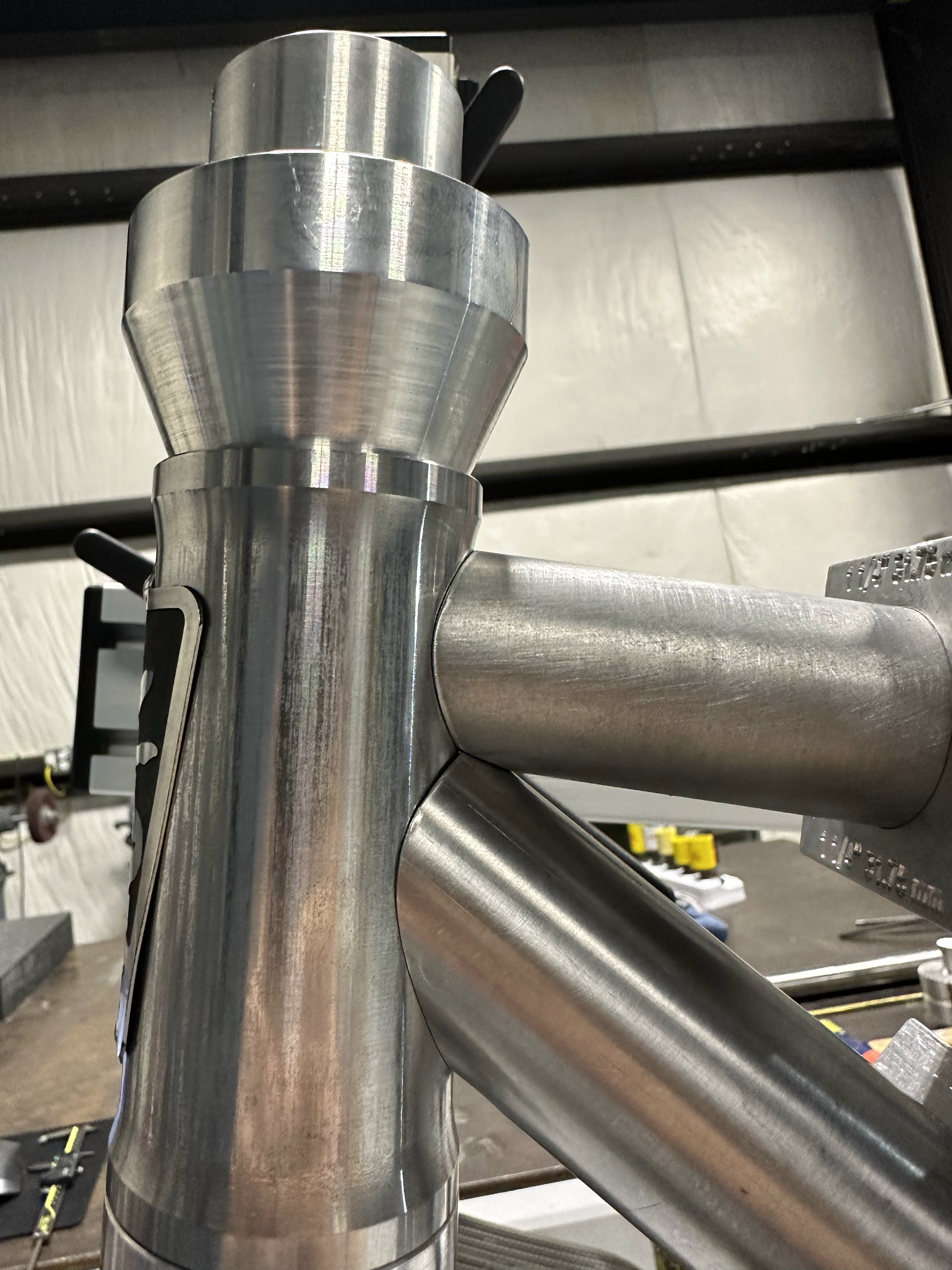
Head tube

Drive side dropout.
Assembled frame in the machine shop.

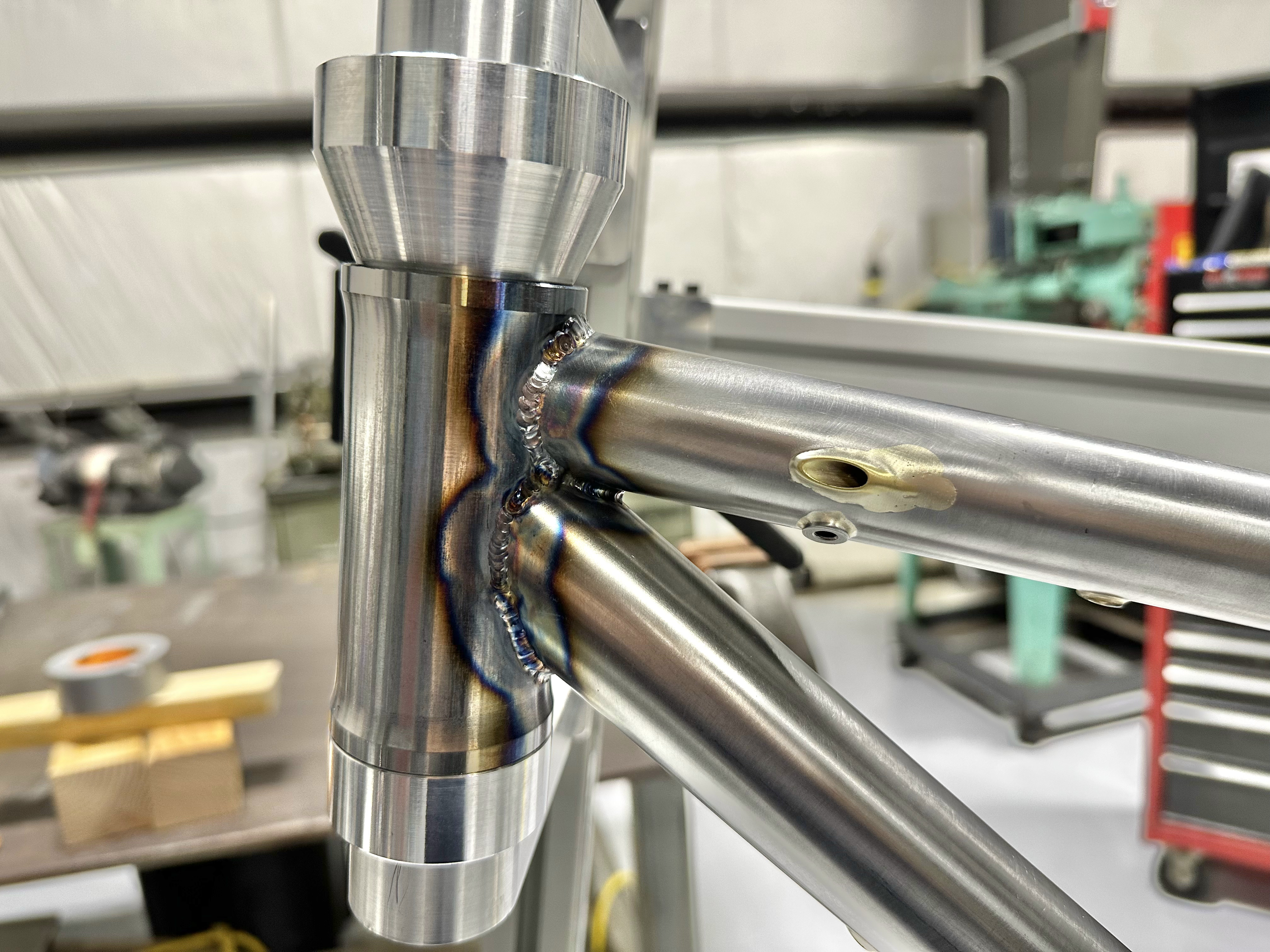
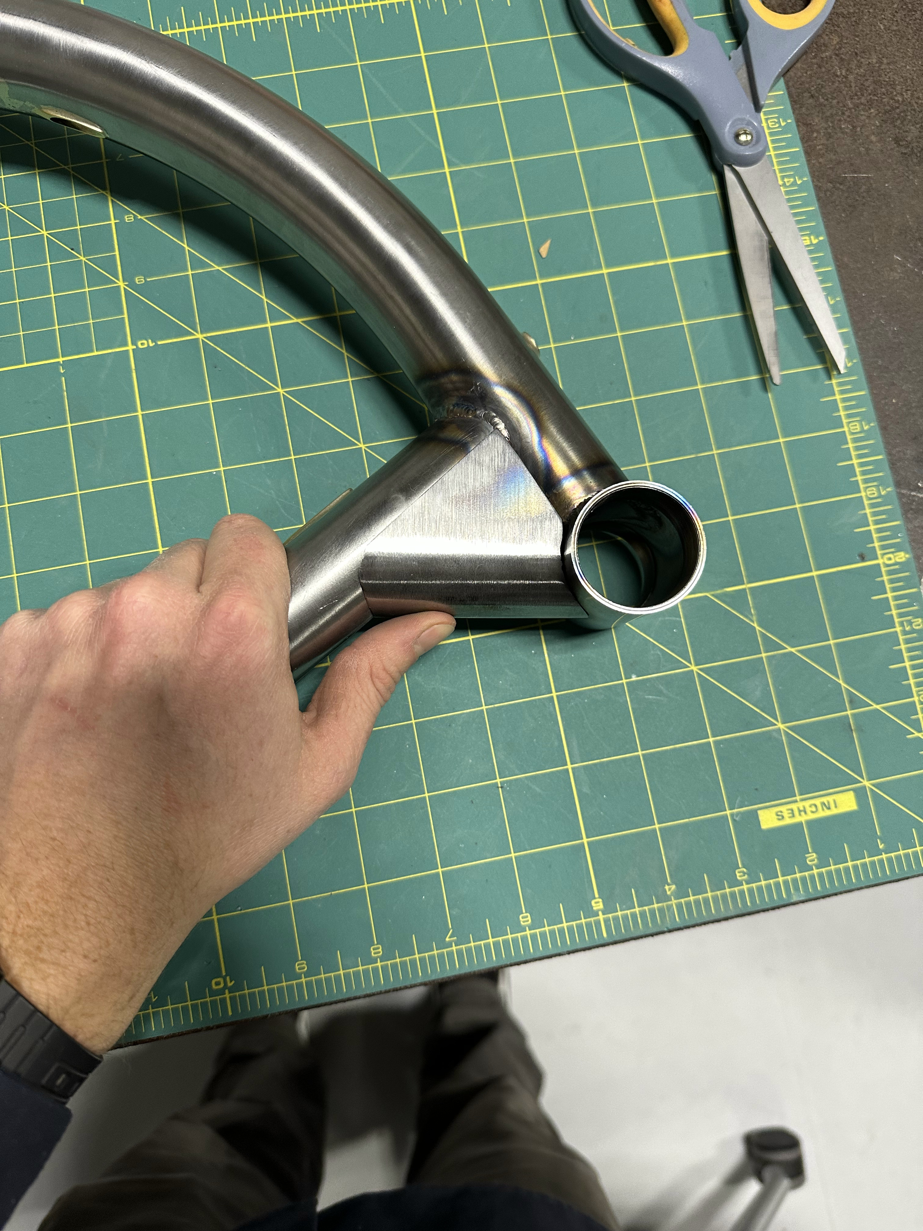
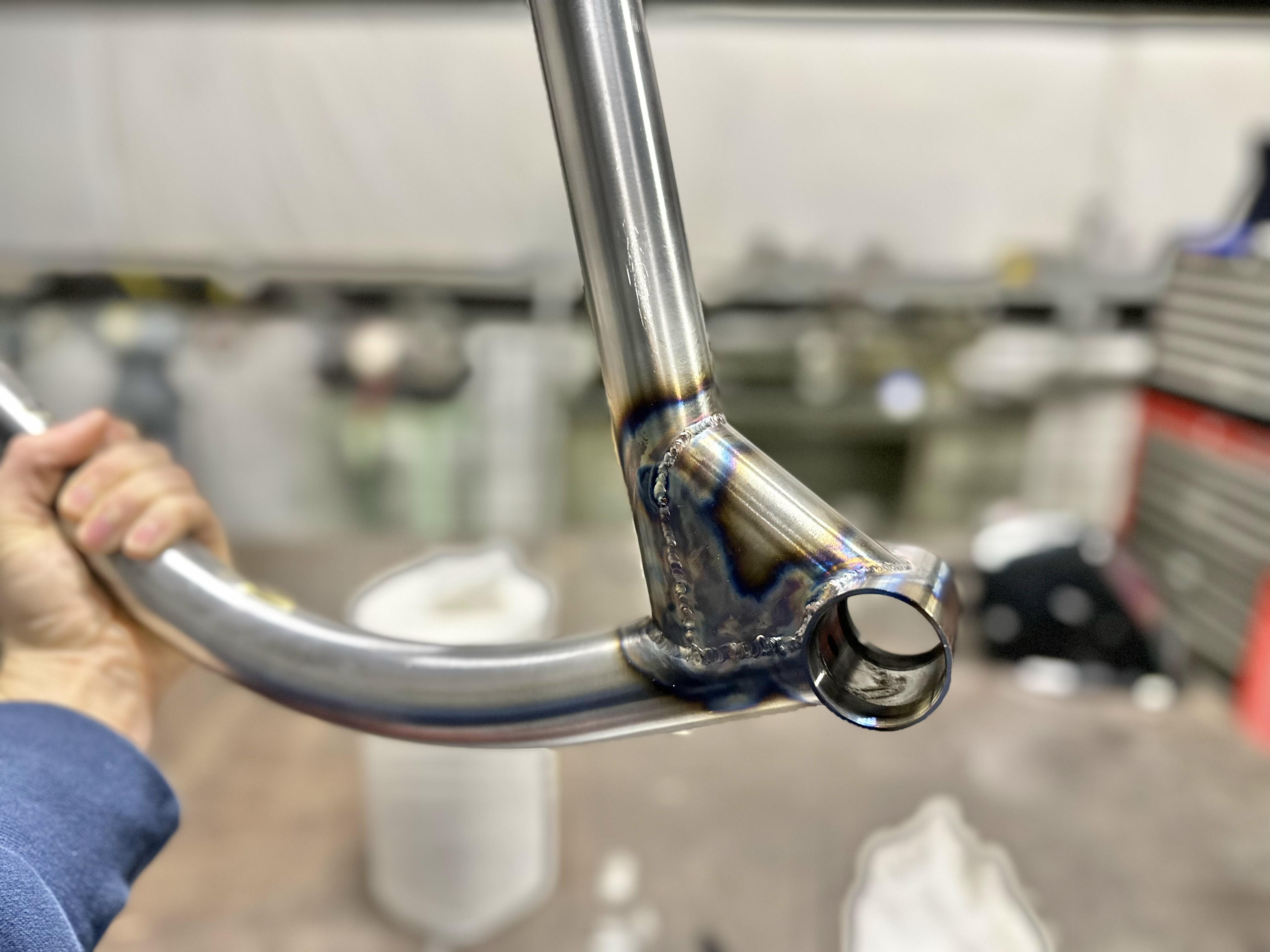
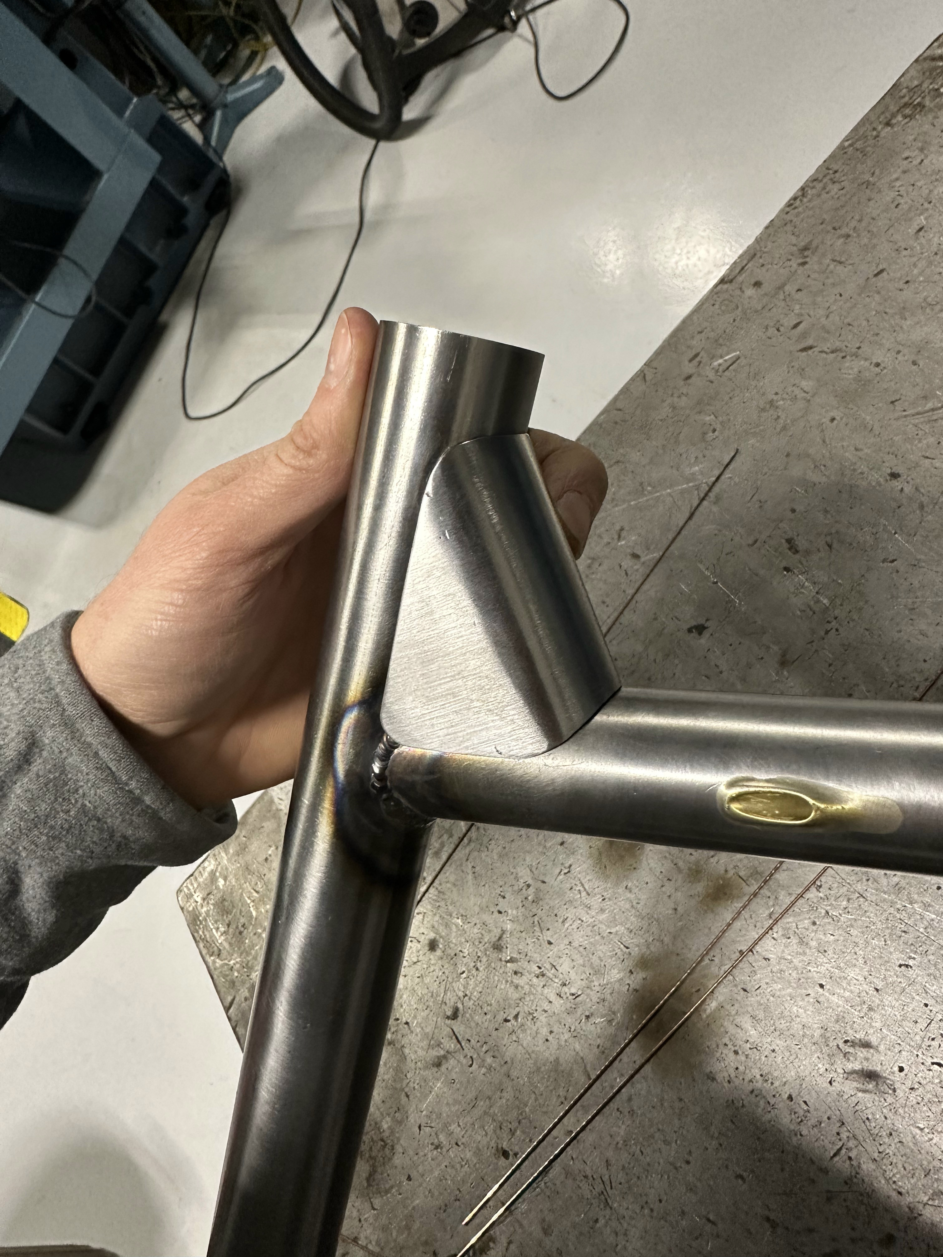
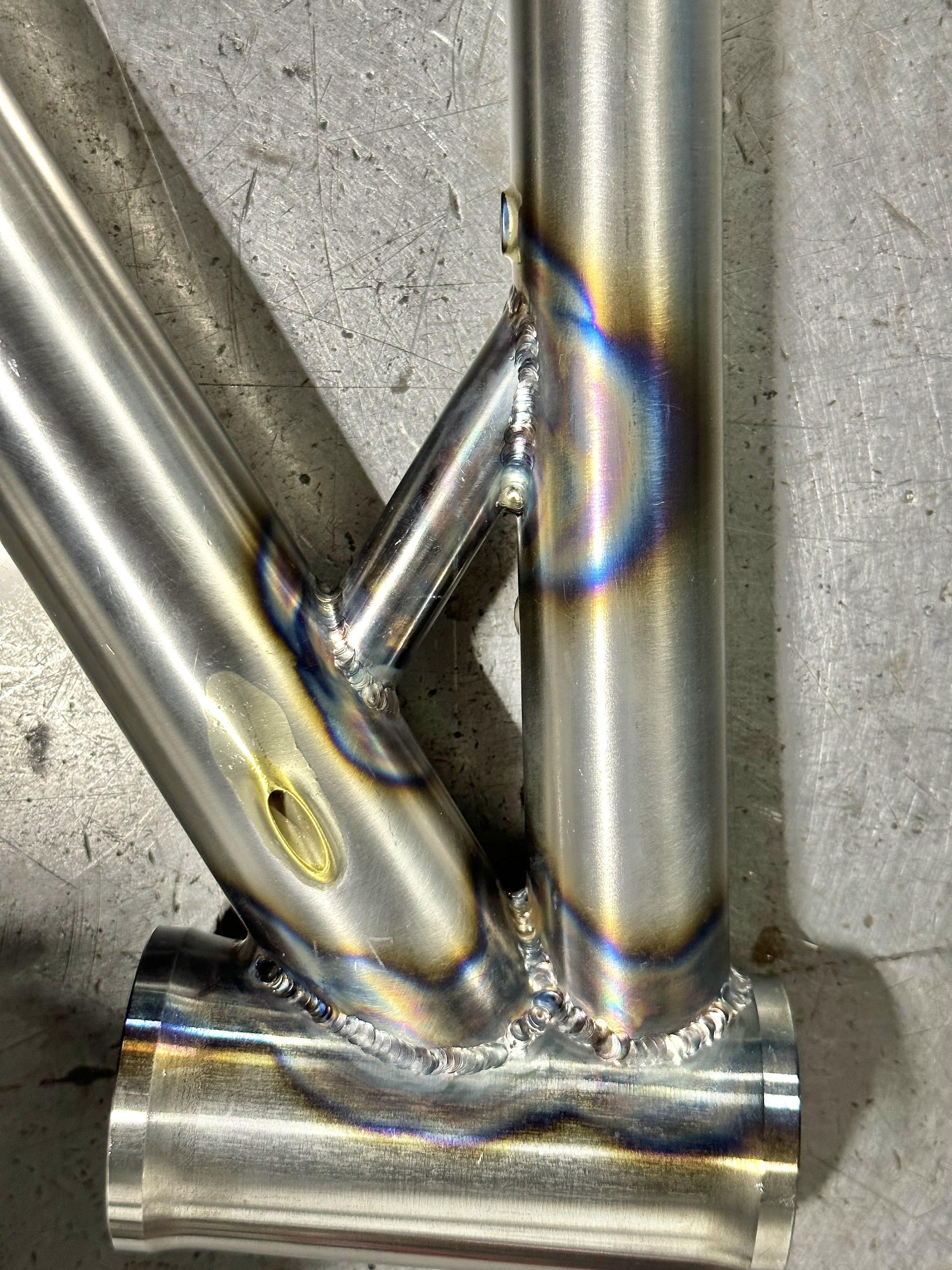
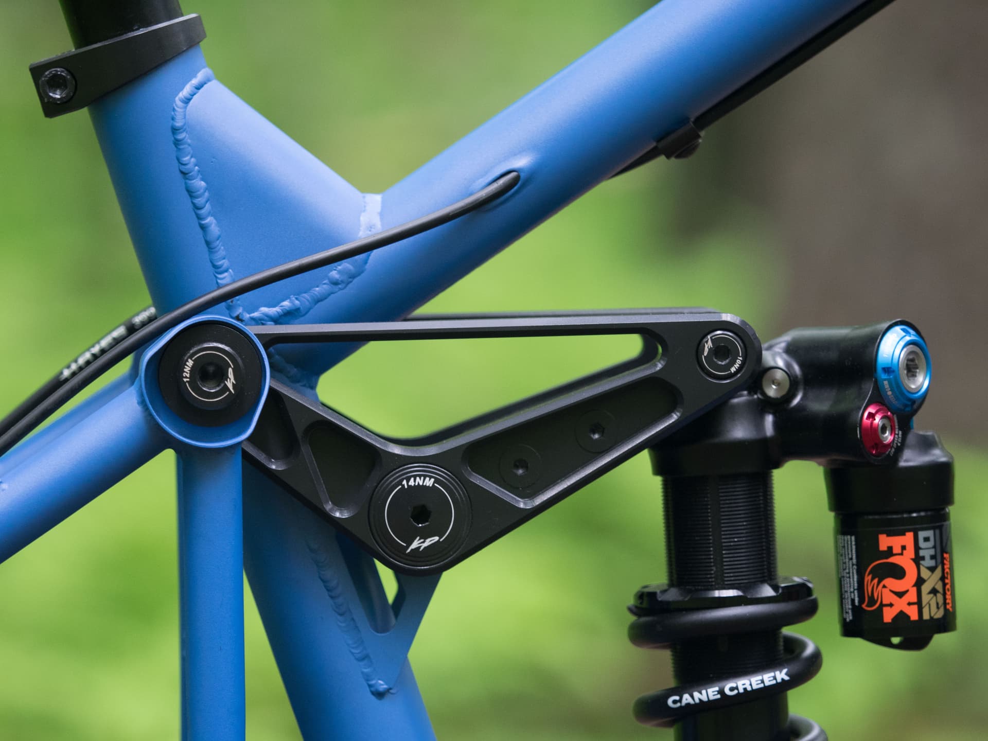
Top tube, seat tube, seat stay junction as seen from the non-drive side.
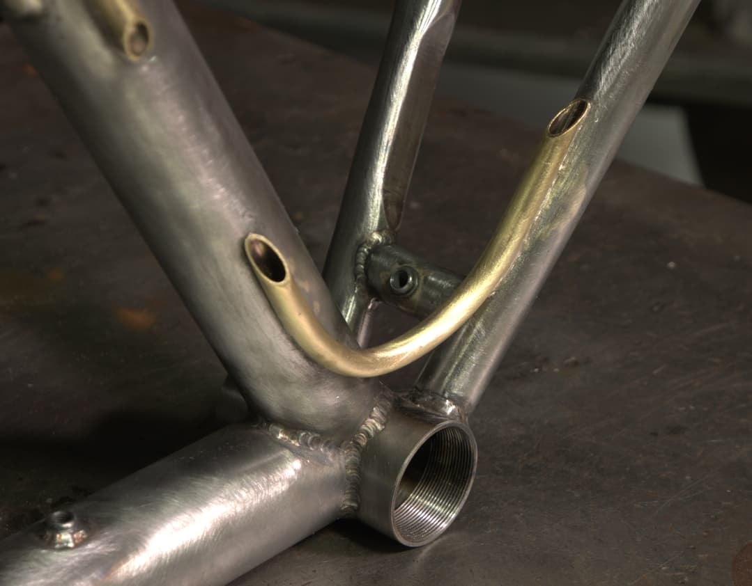
Bottom bracket junction.

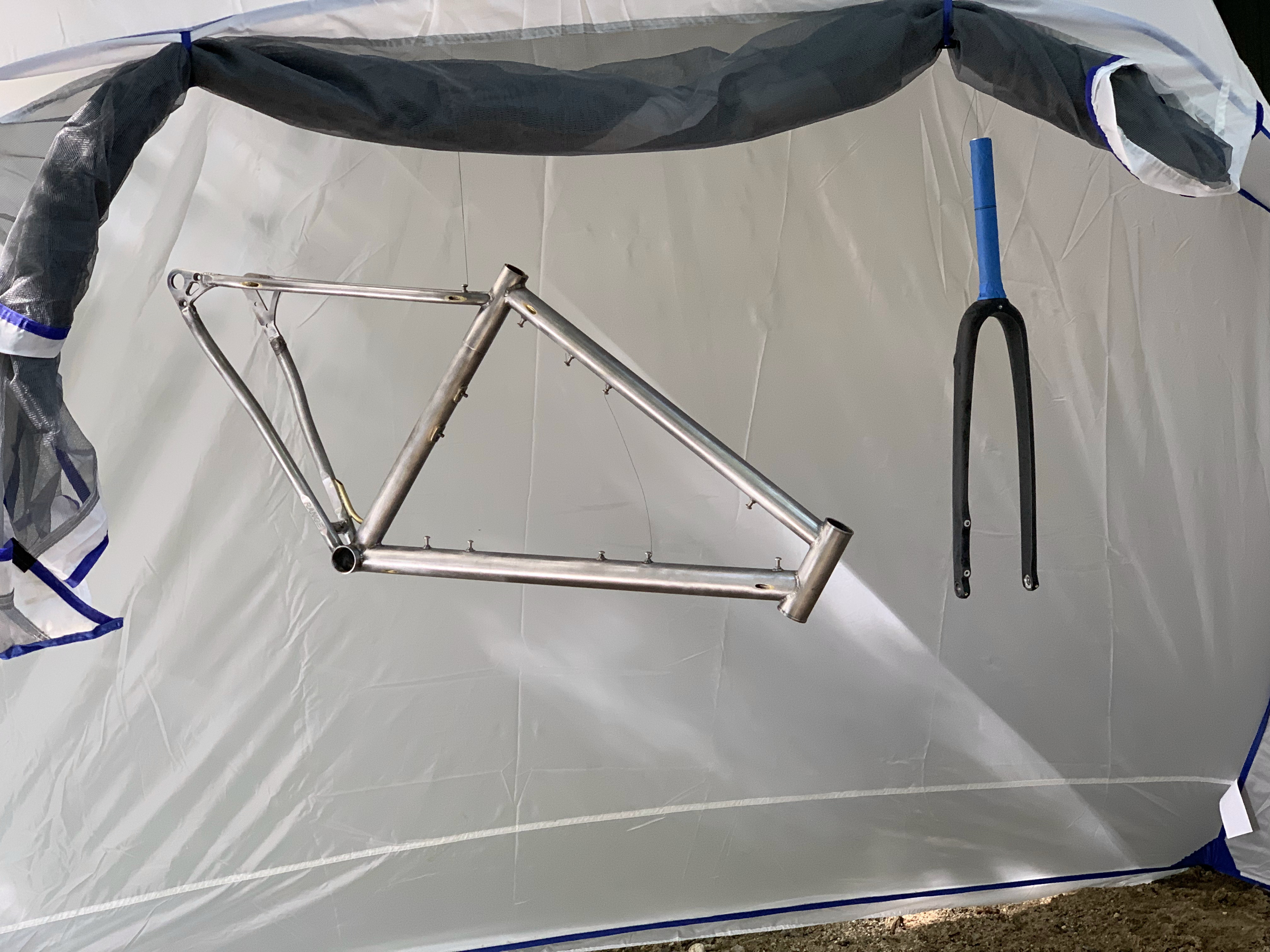
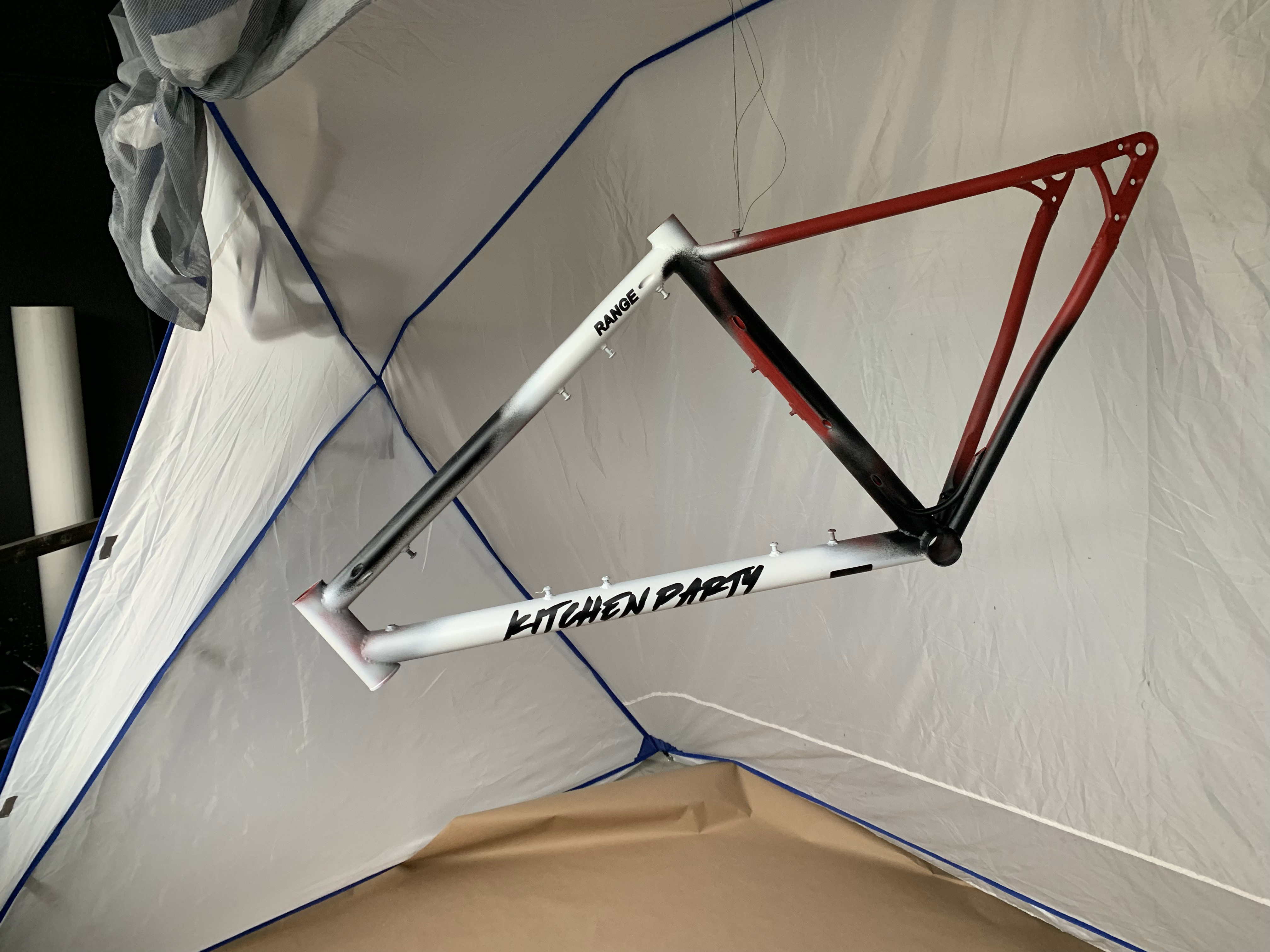
I bought a paint tent and suspended the frame and fork from the deck of my friend’s house.
I used paint from spray.bike to paint this frame and I used vinyl stencils I cut out using a Silhouette Cameo 4 vinyl cutter. The vinyl cutter was pretty rad and worked great. The spray.bike paint on the other hand, did not work as anticipated. The process took longer than expected and it got cold and humid into the night so the paint did not adhere very well.

The four-burner pattern peeled off some of the paint.
I ended up removing the initial paint with acetone, bringing the frame back into work and trying again with controlled environmental conditions. I probably should have left it with this paintjob, it looks sick.

Masked off for a third coat of paint. This paint job came out much better, but the paint was very fragile. Overall I am not a big fan of spray.bike’s offerings. I found that loctite would even act as a solvent against the paint.

So I decided to make a custom “ride wrap” coating for the frame using 3M scotchguard clear protective tape. I realize this is probably a bit of a faux pas in the custom frame world, but I knew this paint would get beat to hell the way I ride bikes. I was able to model the wrap patterns with relative ease for all the tubing. The fork gave me some difficulties. I ended up tailoring a piece of kraft paper around the fork, cutting away material until it covered the fork. It came out less than ok, but the rest of the frame looked great. The glossy film really made the previously matte finish frame pop and shine.

Finished frame in the shop.

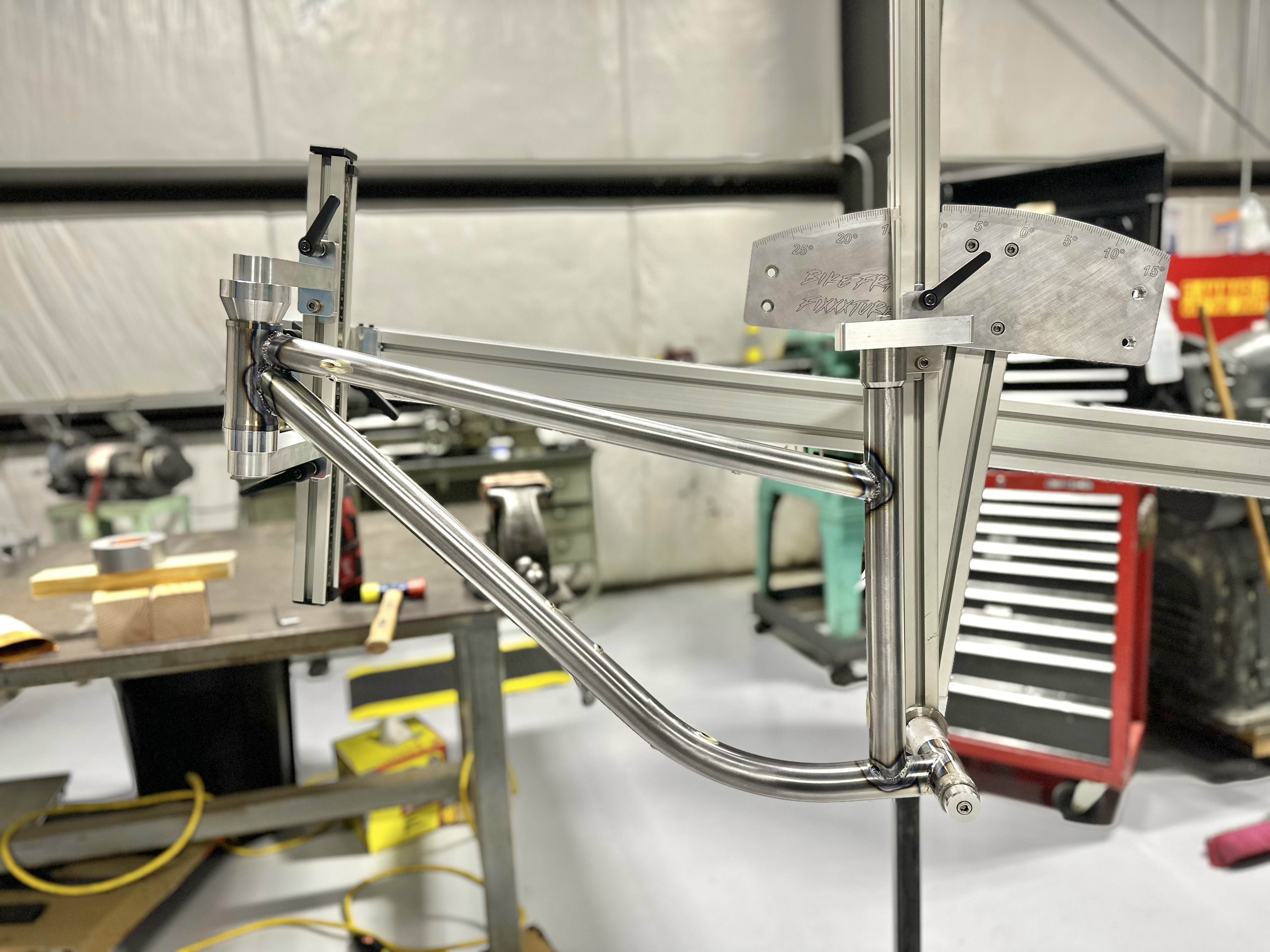
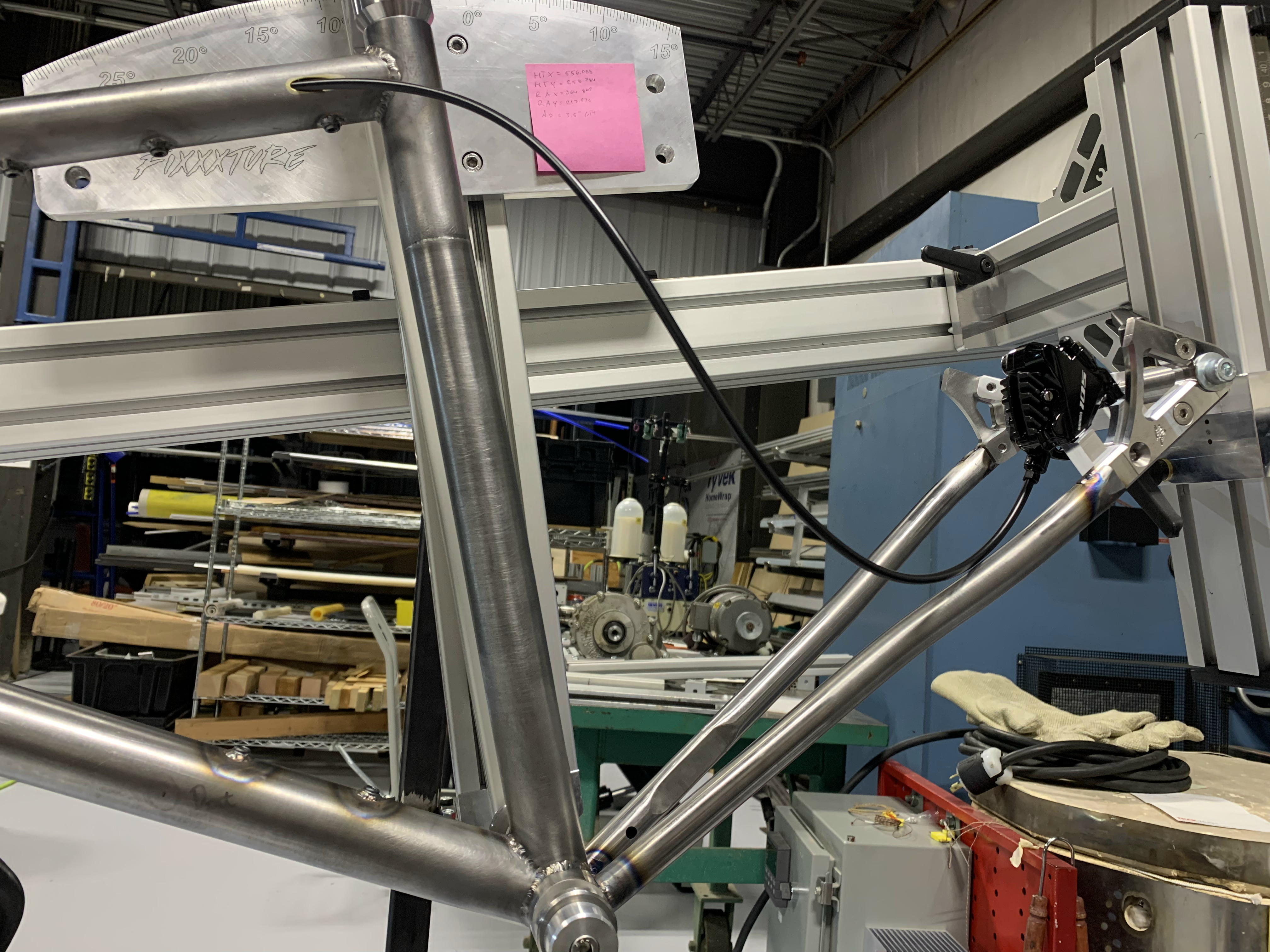
Finished frame in the fixture.
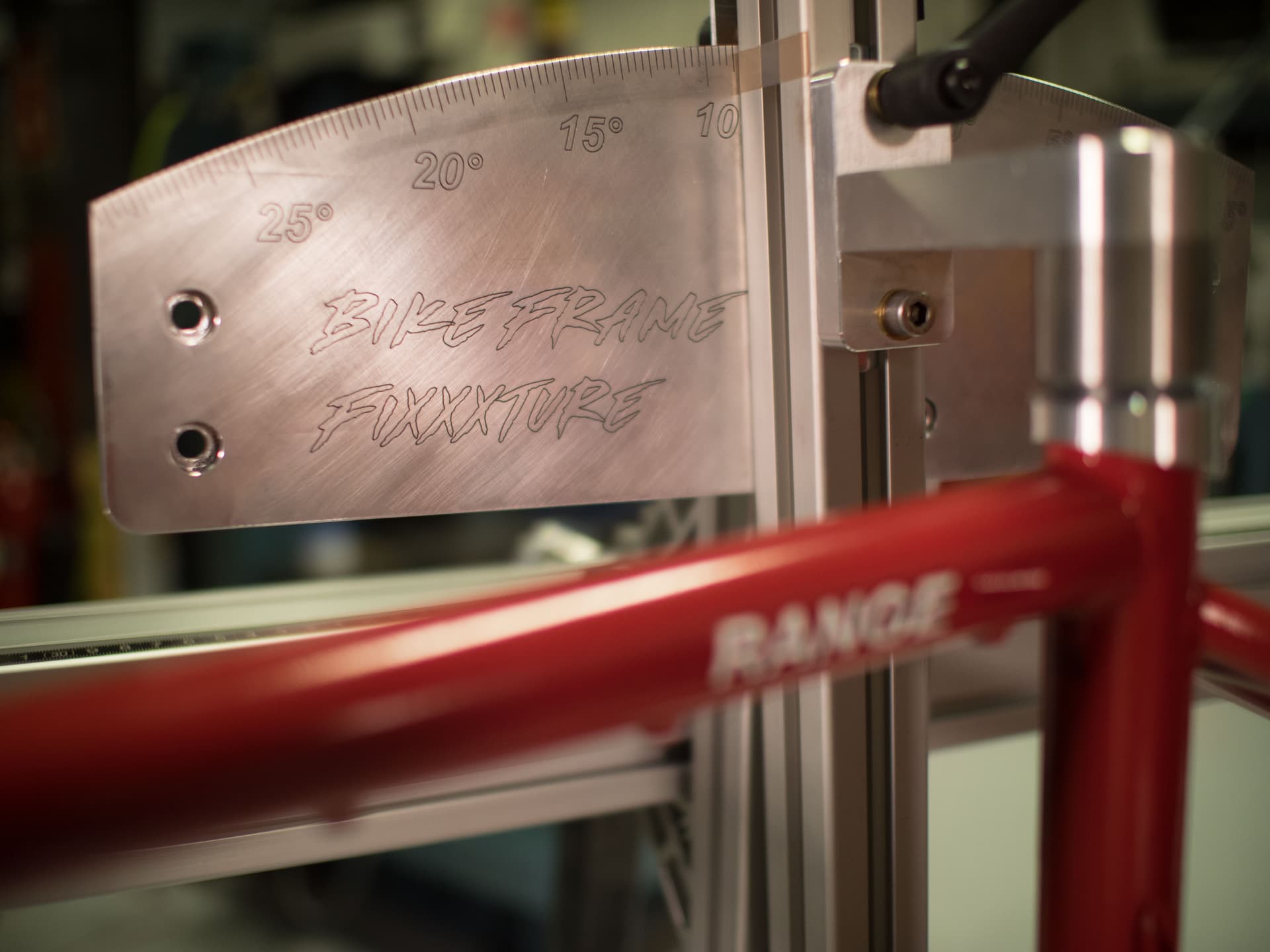
Showing off the frame fixxxture angle plate.
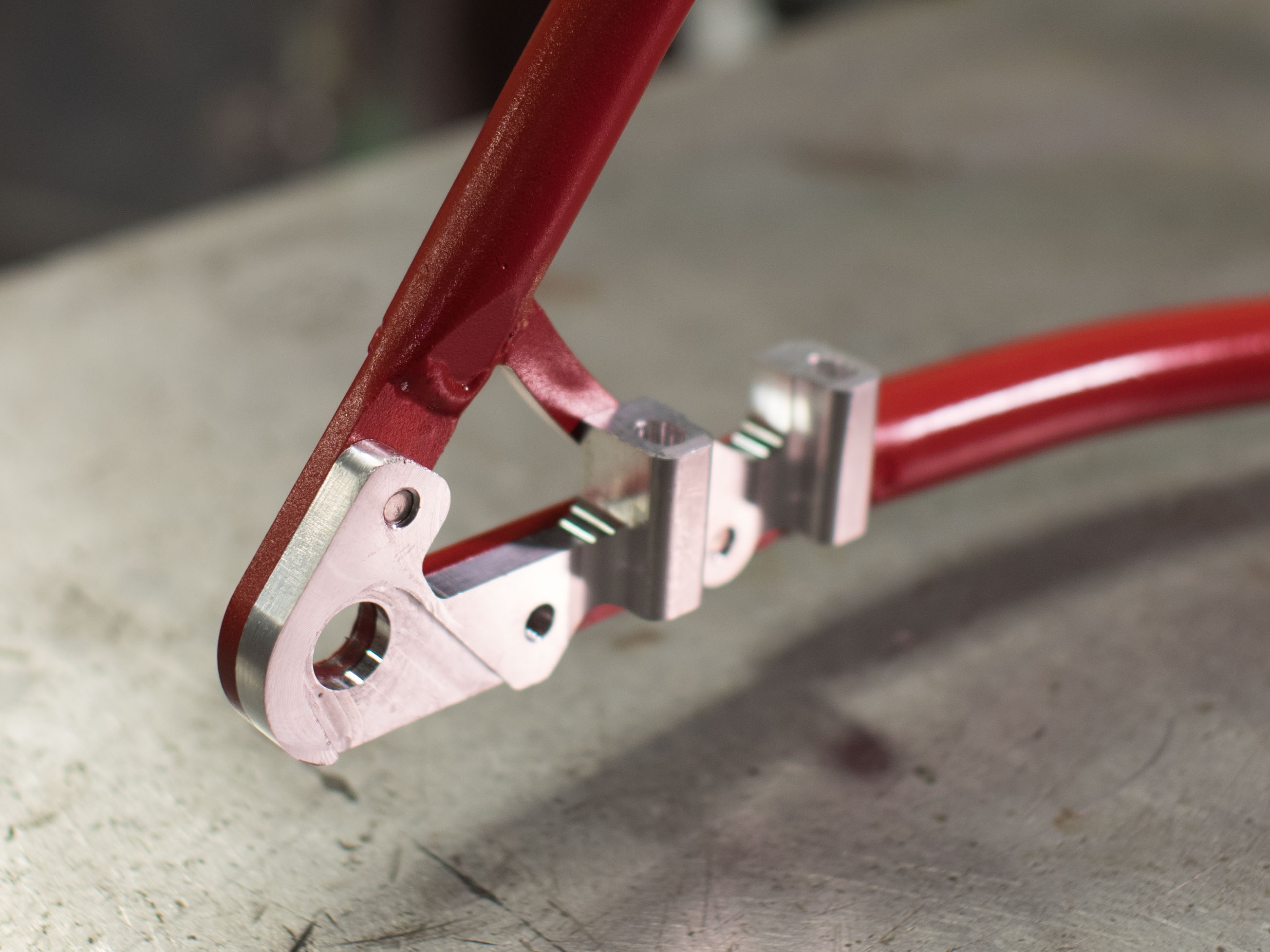
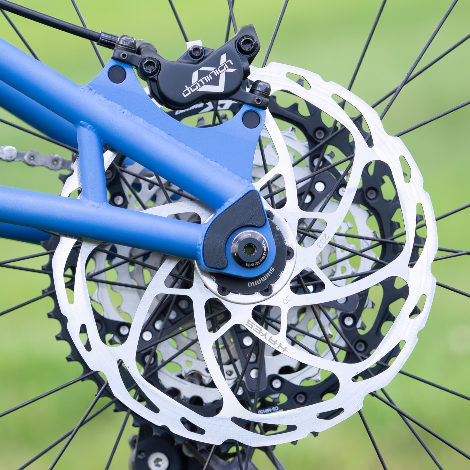
non-drive side dropout with integrated flat mount.
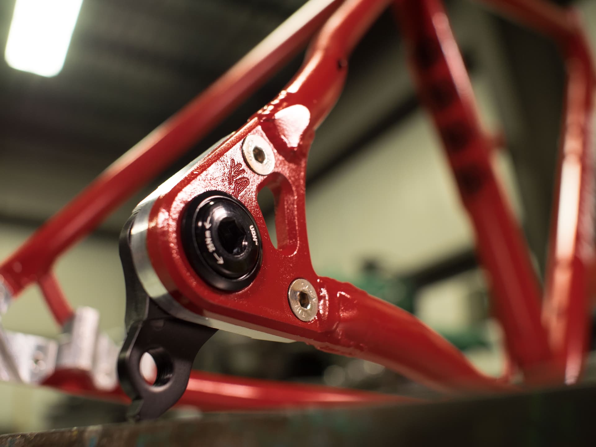
Drive side dropout
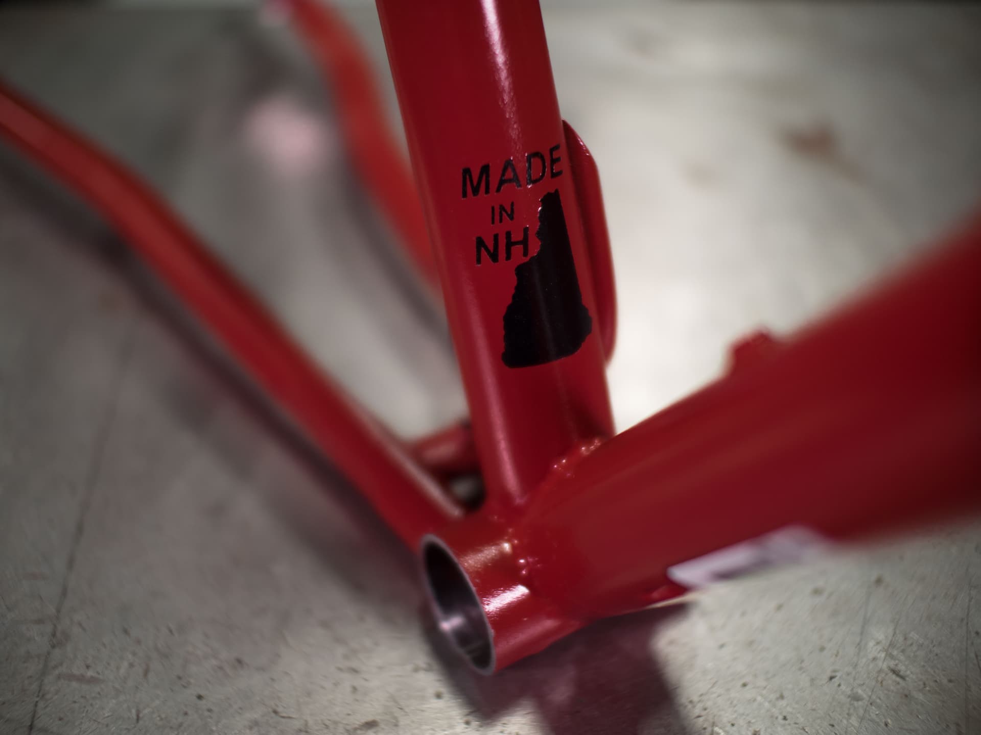
Channeling my inner Kris Henry @44bikes.

Range appliance graphic.
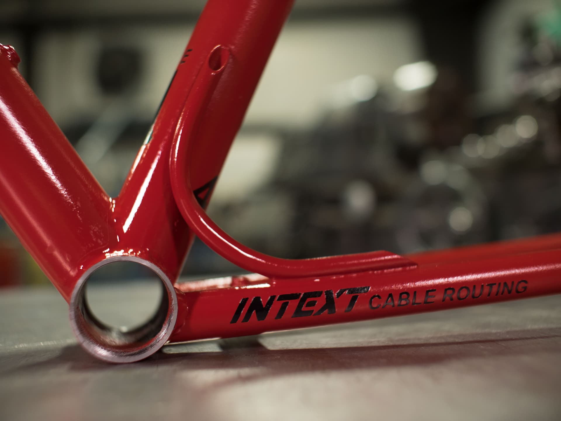
Intext cable routing - Fake BS marketing name for my fucked up internal-external cable routing.
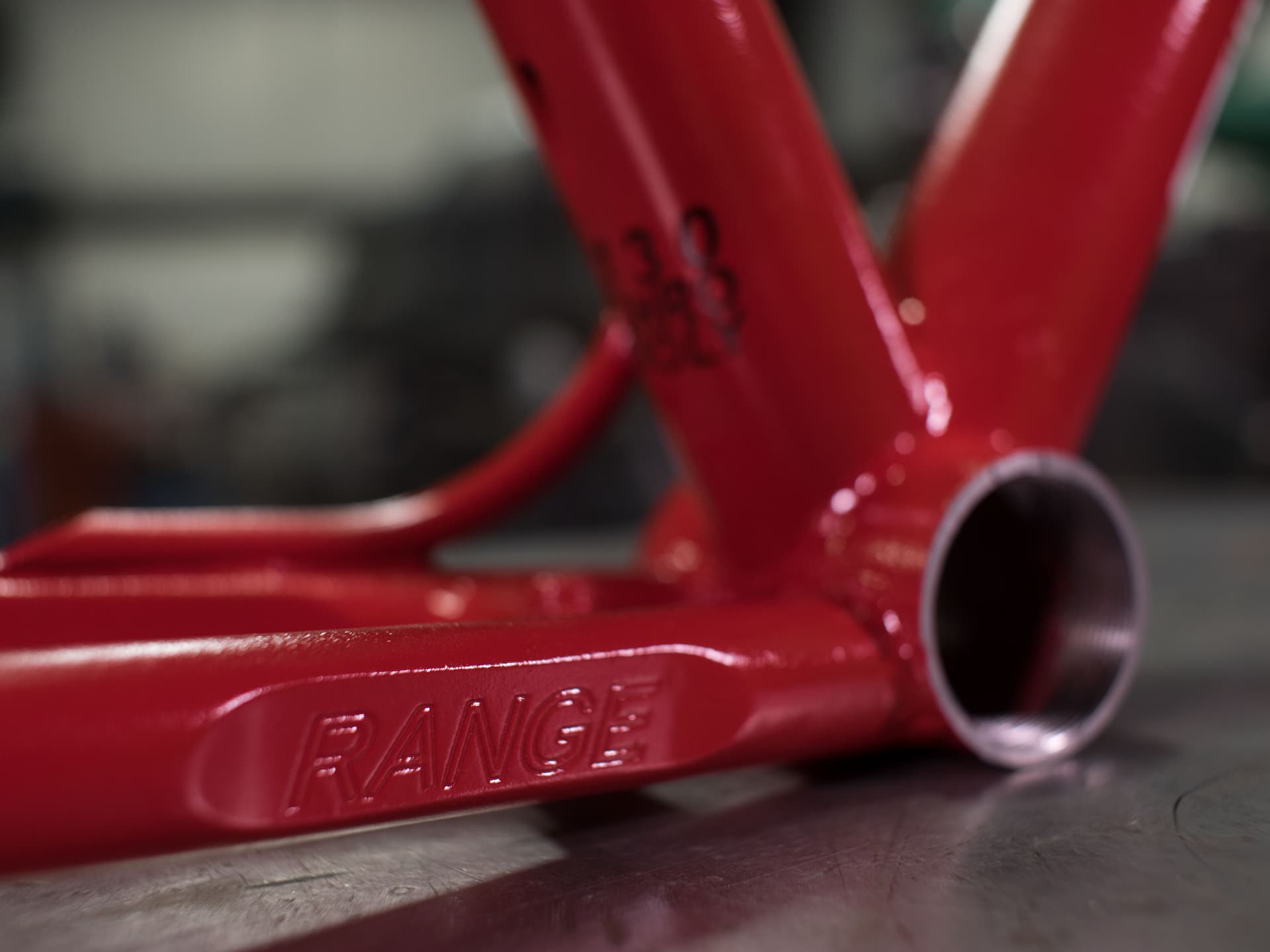
Chainstay clearance patch.
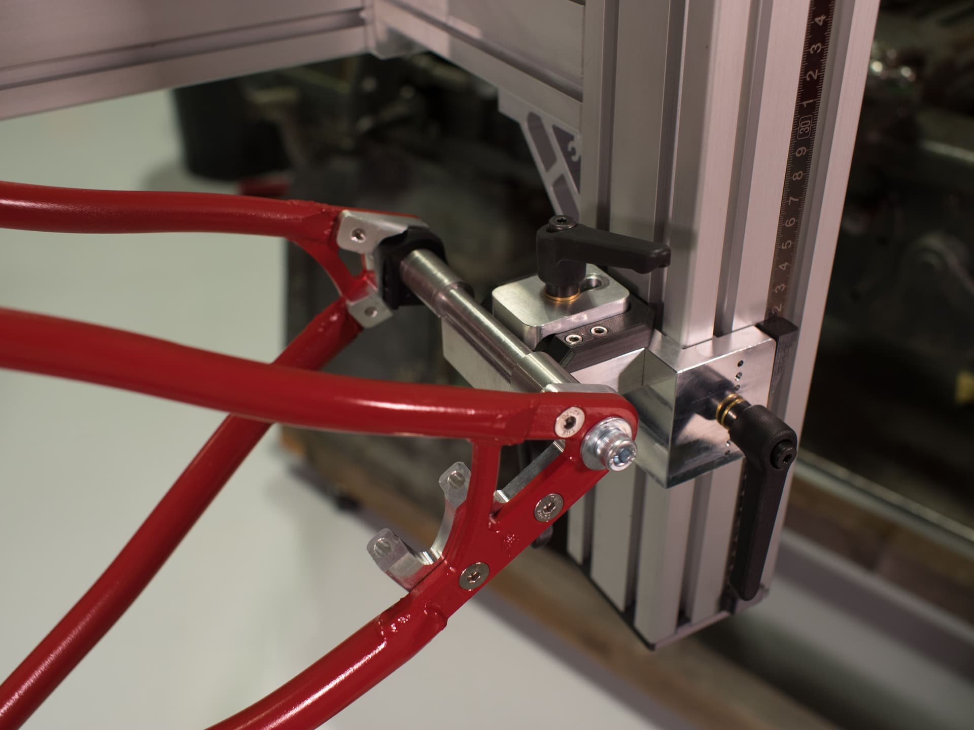
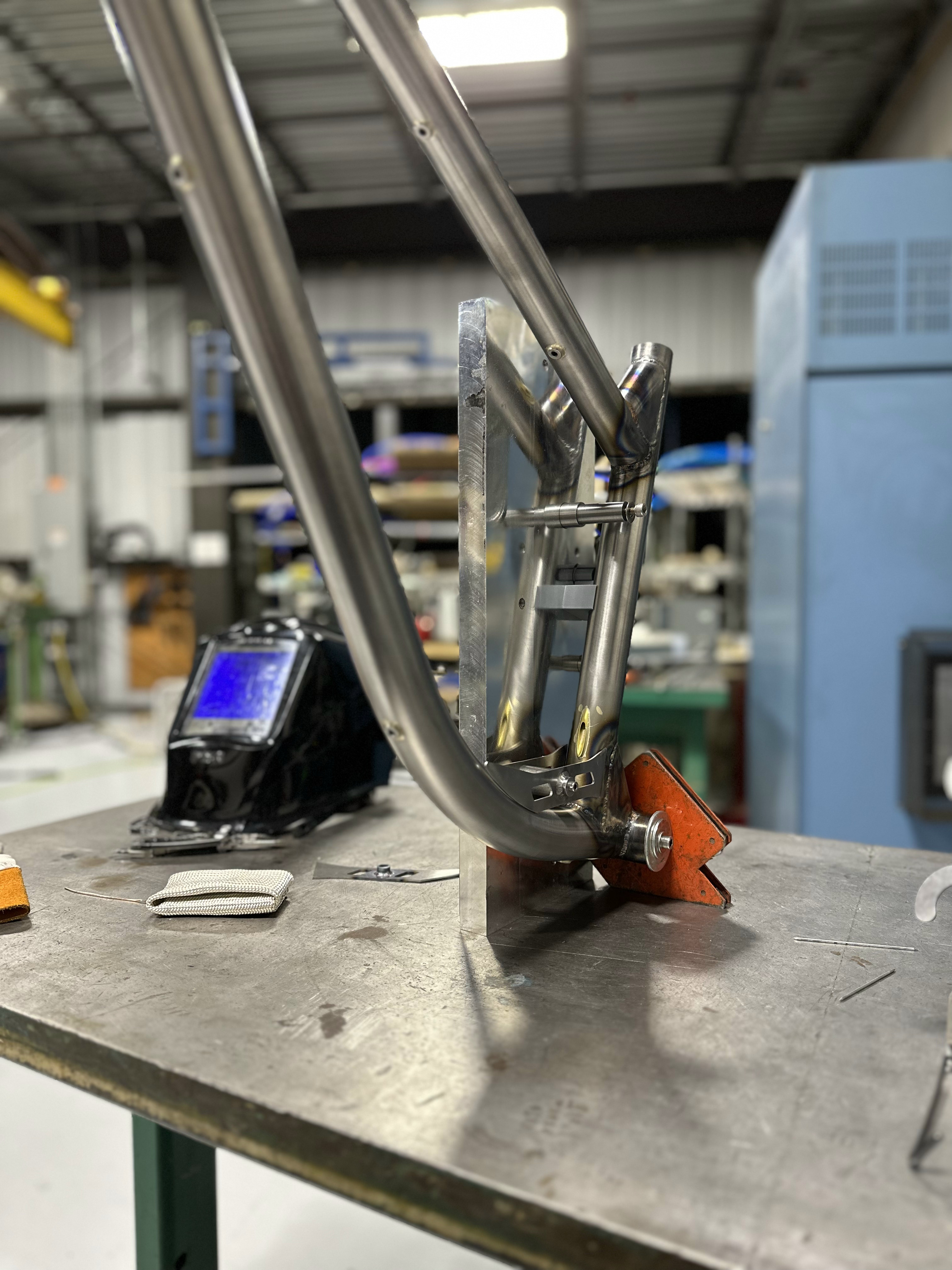
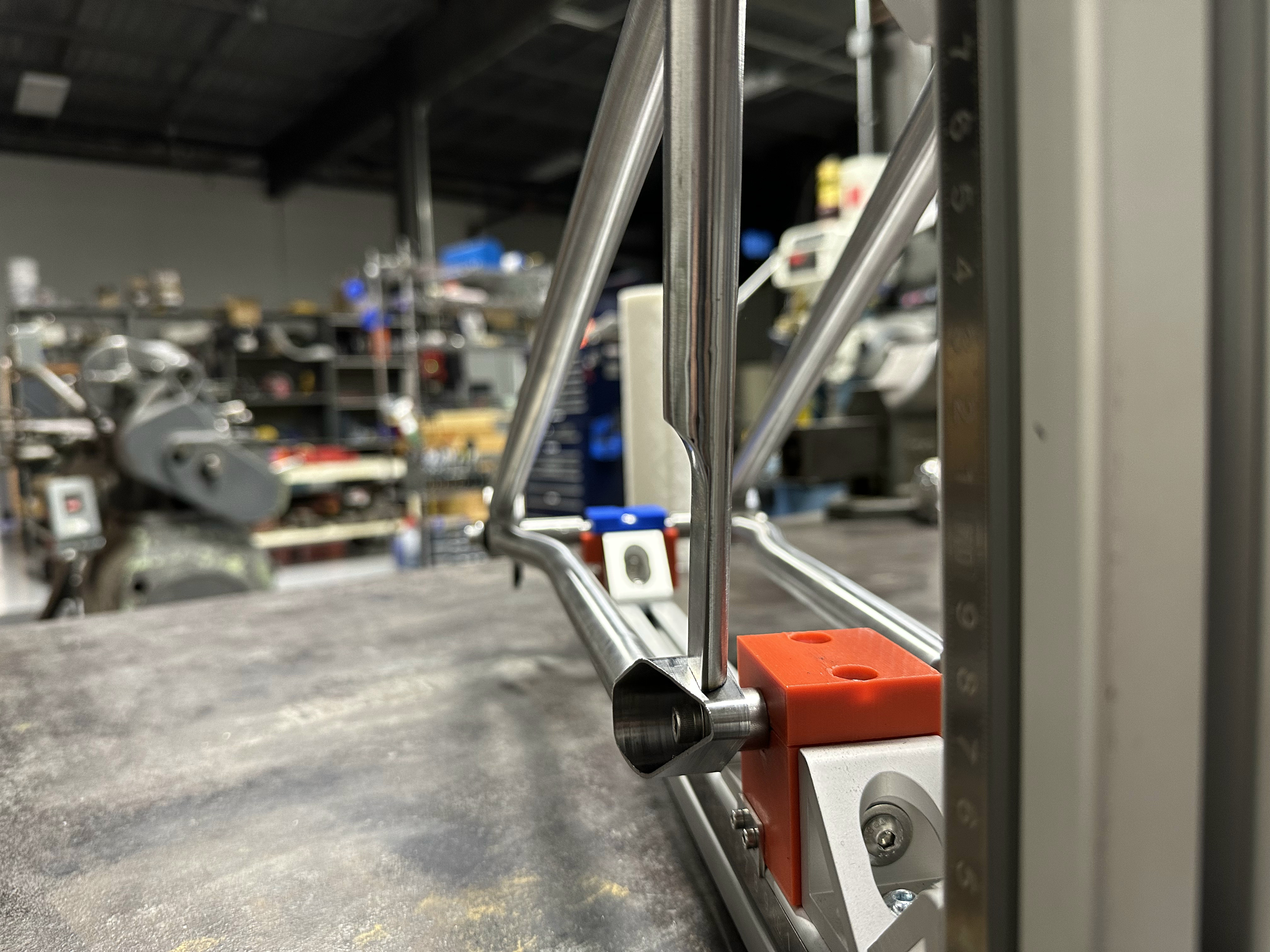
Rear triangle in the frame fixture
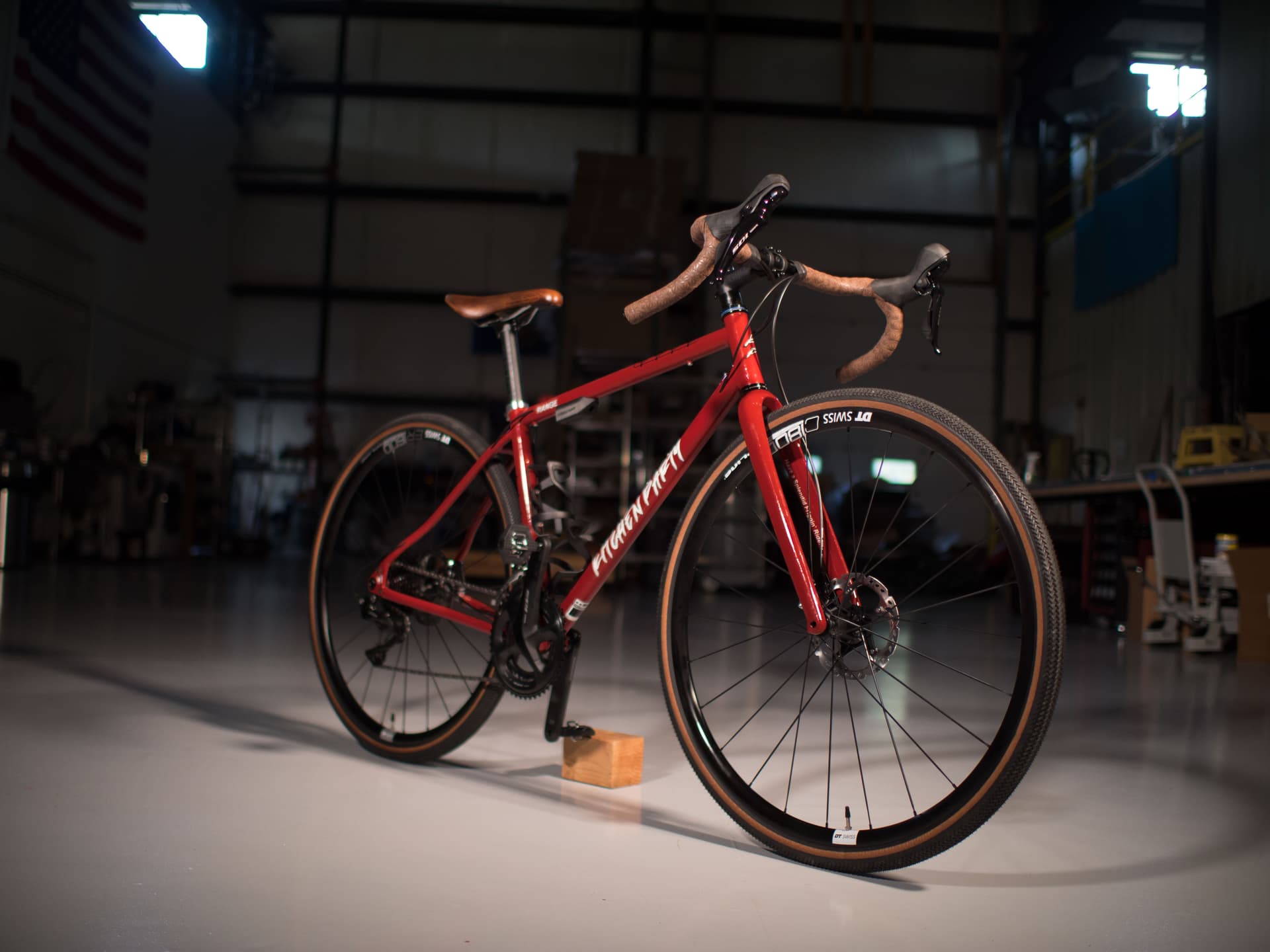
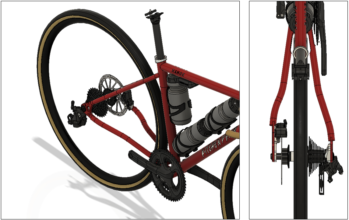
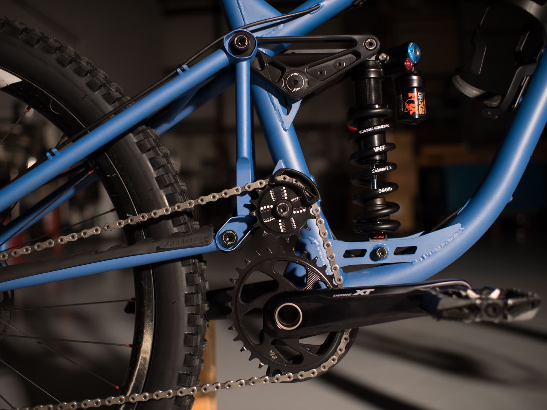
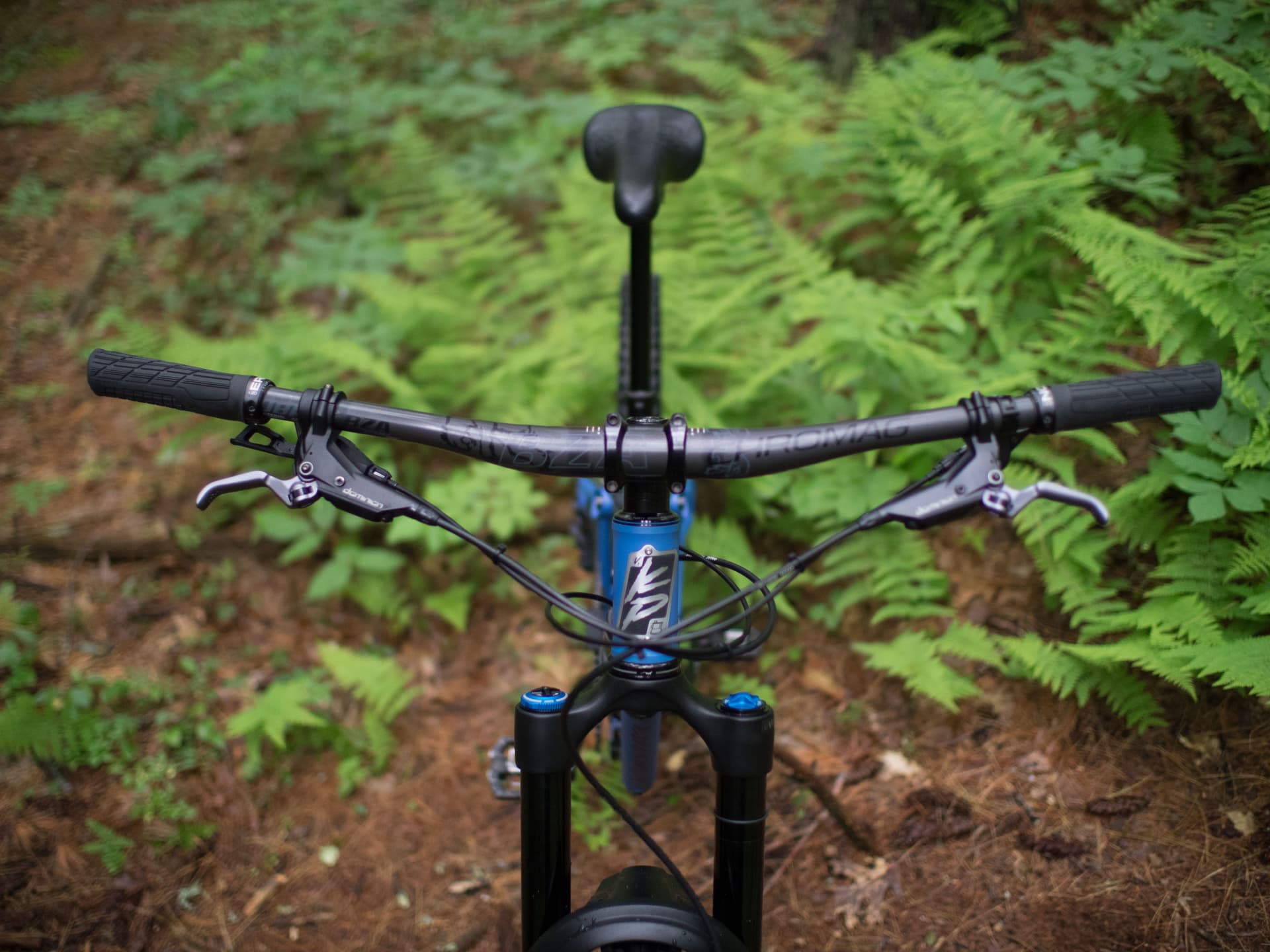
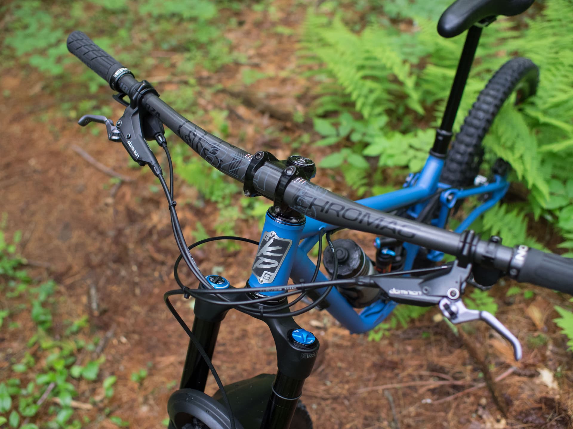
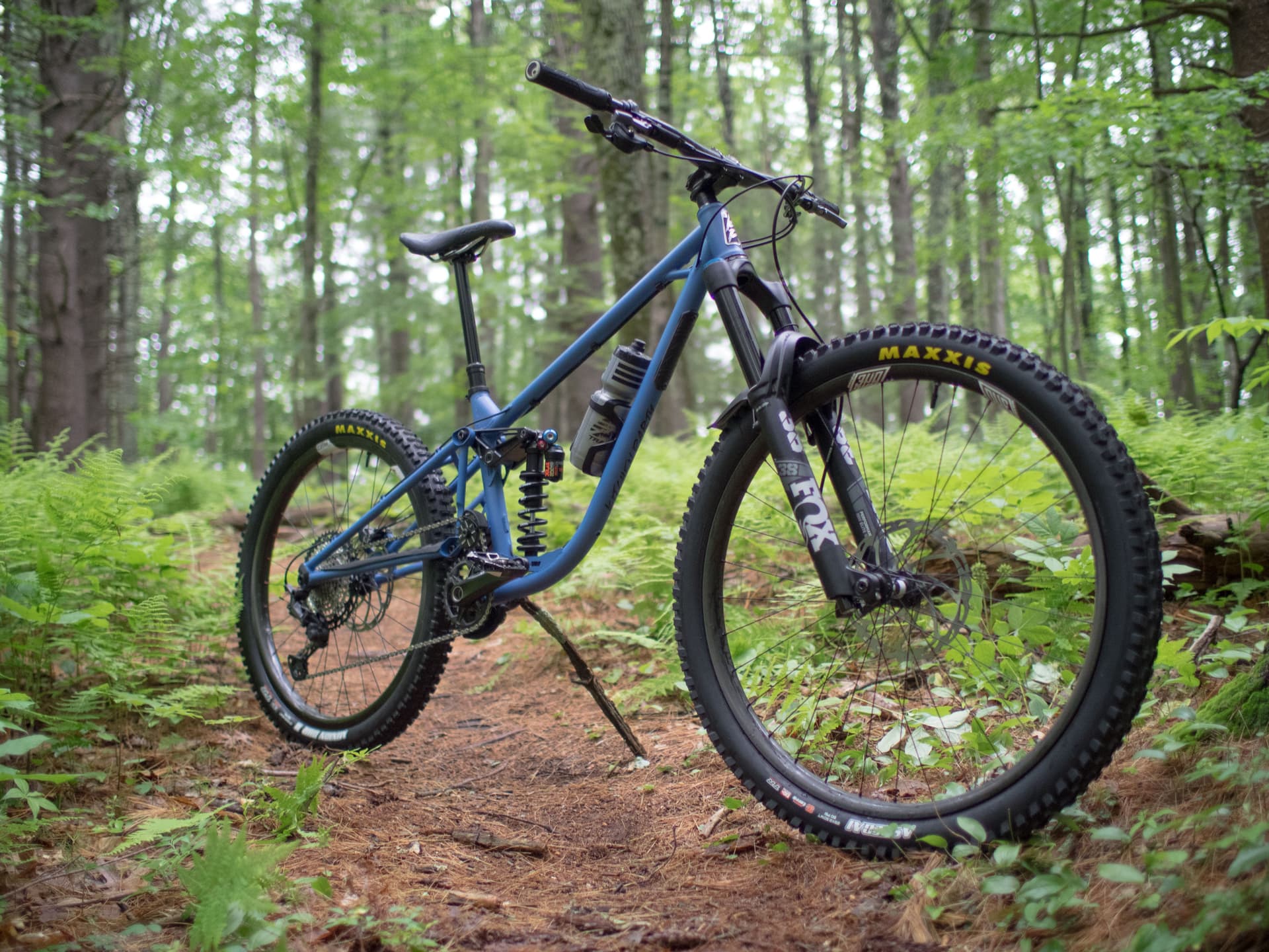
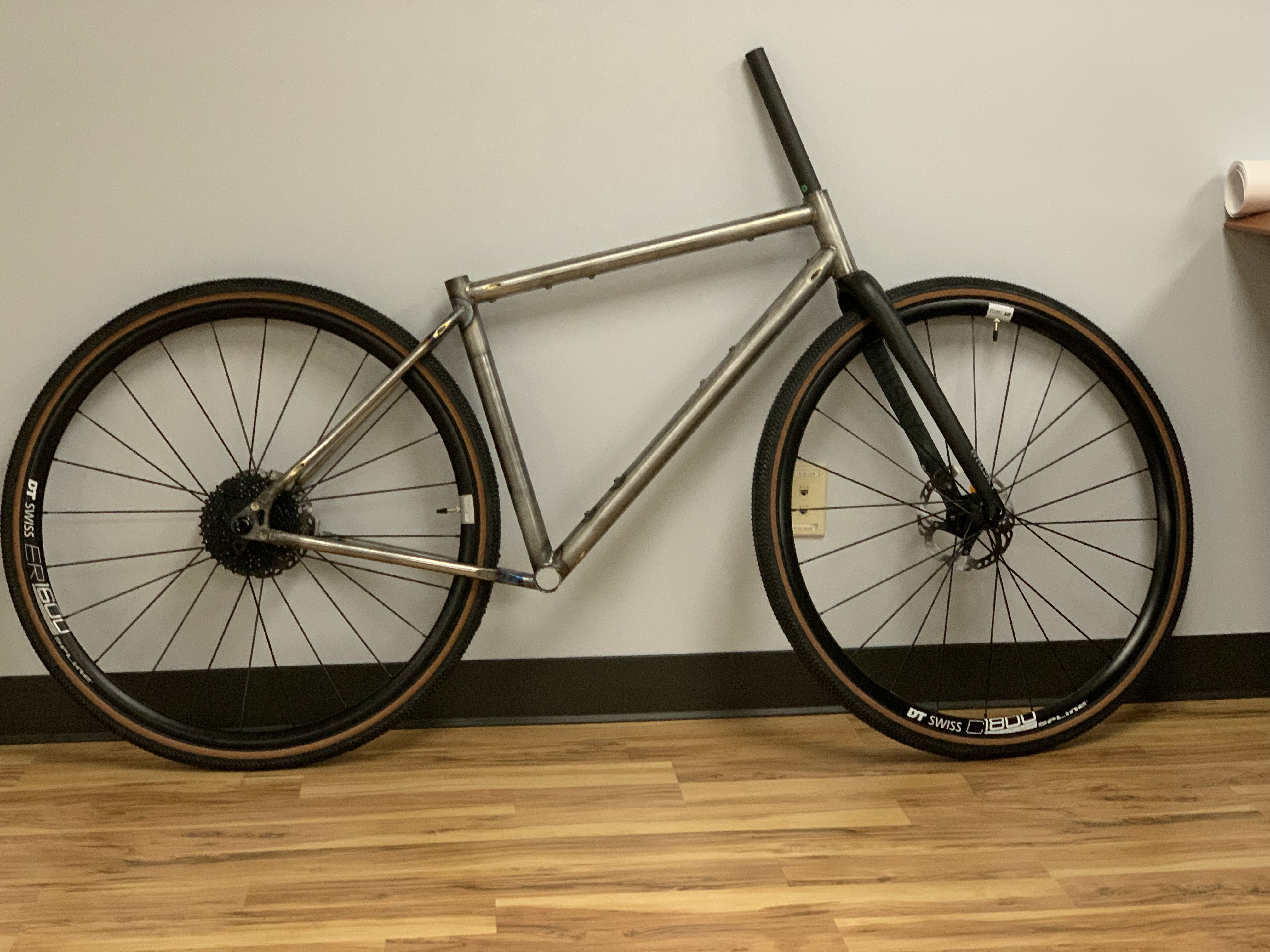
Complete bike built up.

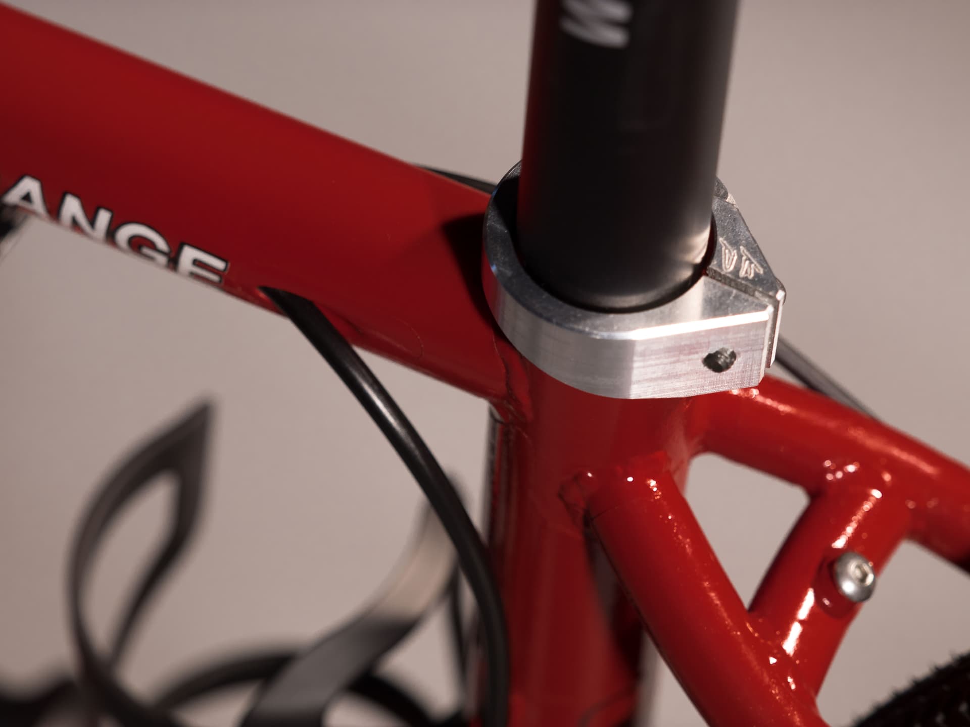
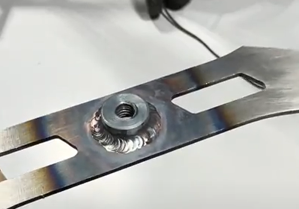
Somewhere along the way I also cut out a seat tube clamp.
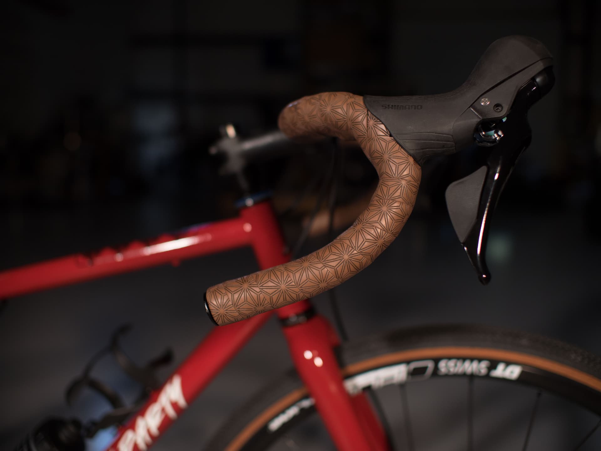
Really psyched about this supacaz bar tape.
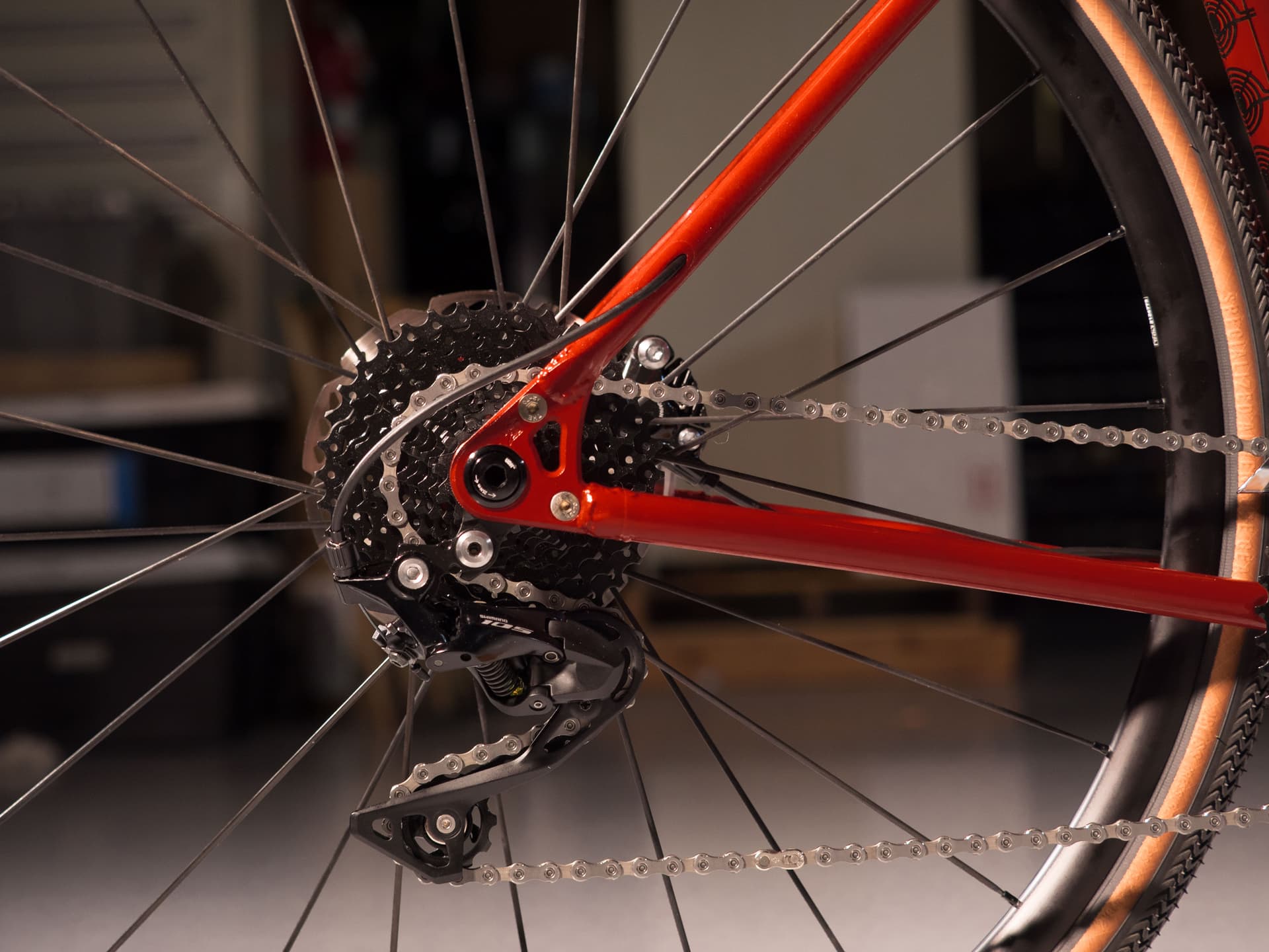
Rear dropout in action.
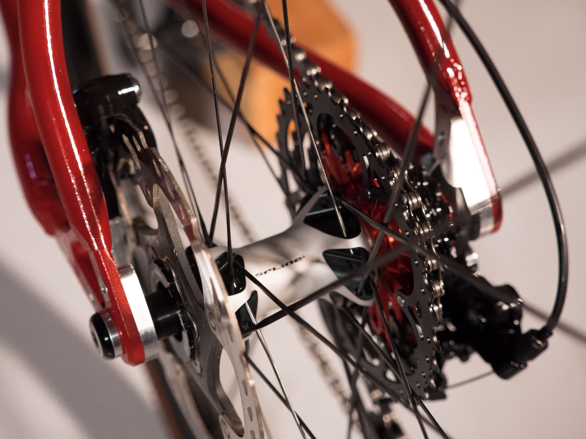
Dropouts and hub interface from another angle.
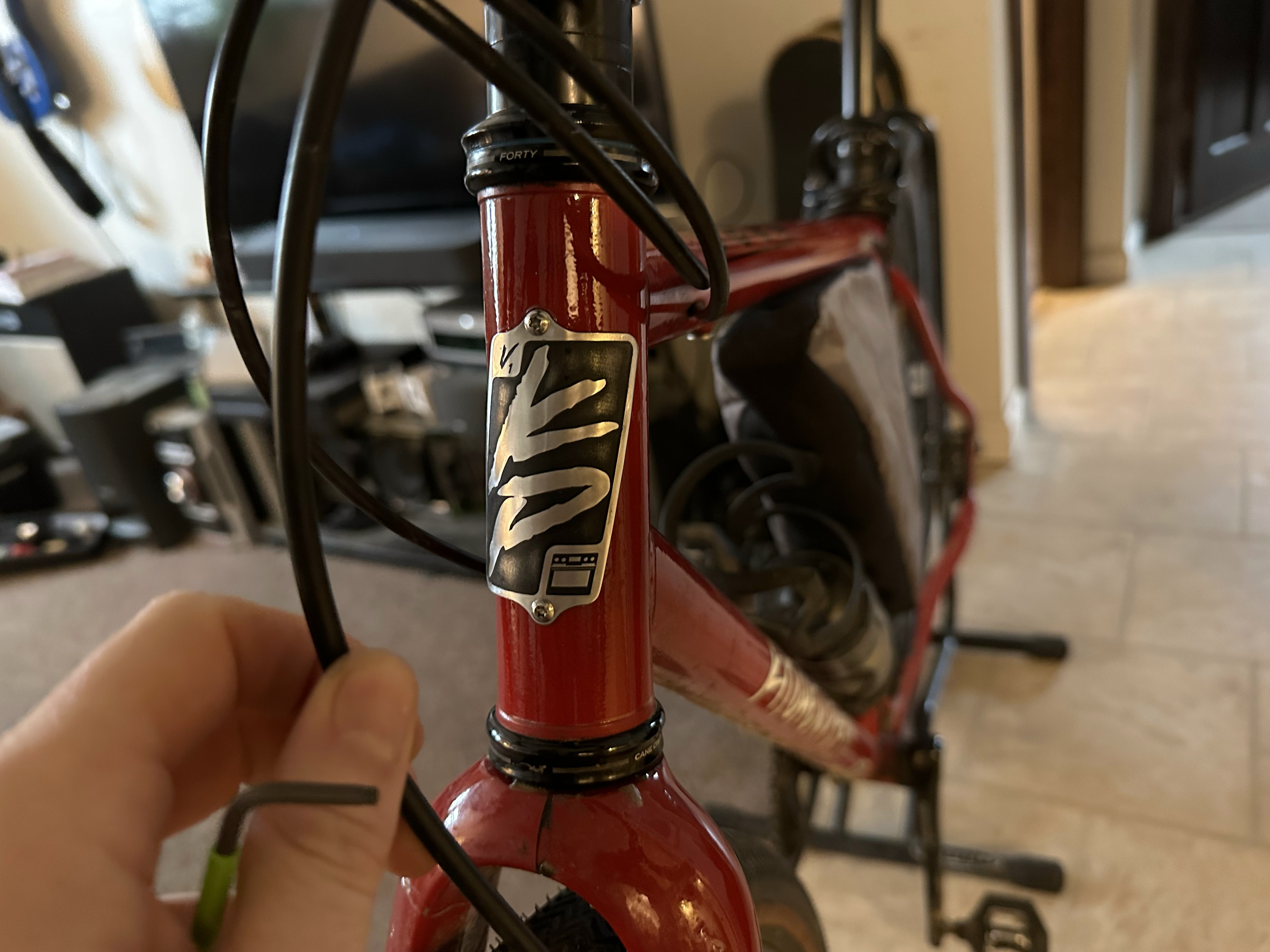
I ended up hand painting the head tube logo and it came out terrible. I was so let down after the Engin cycles inspired engraving didn’t pan out after painting. This bothered me for years until I was able to recently redeem myself.

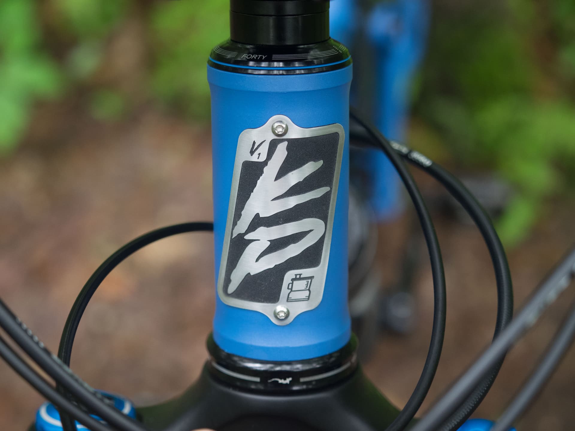
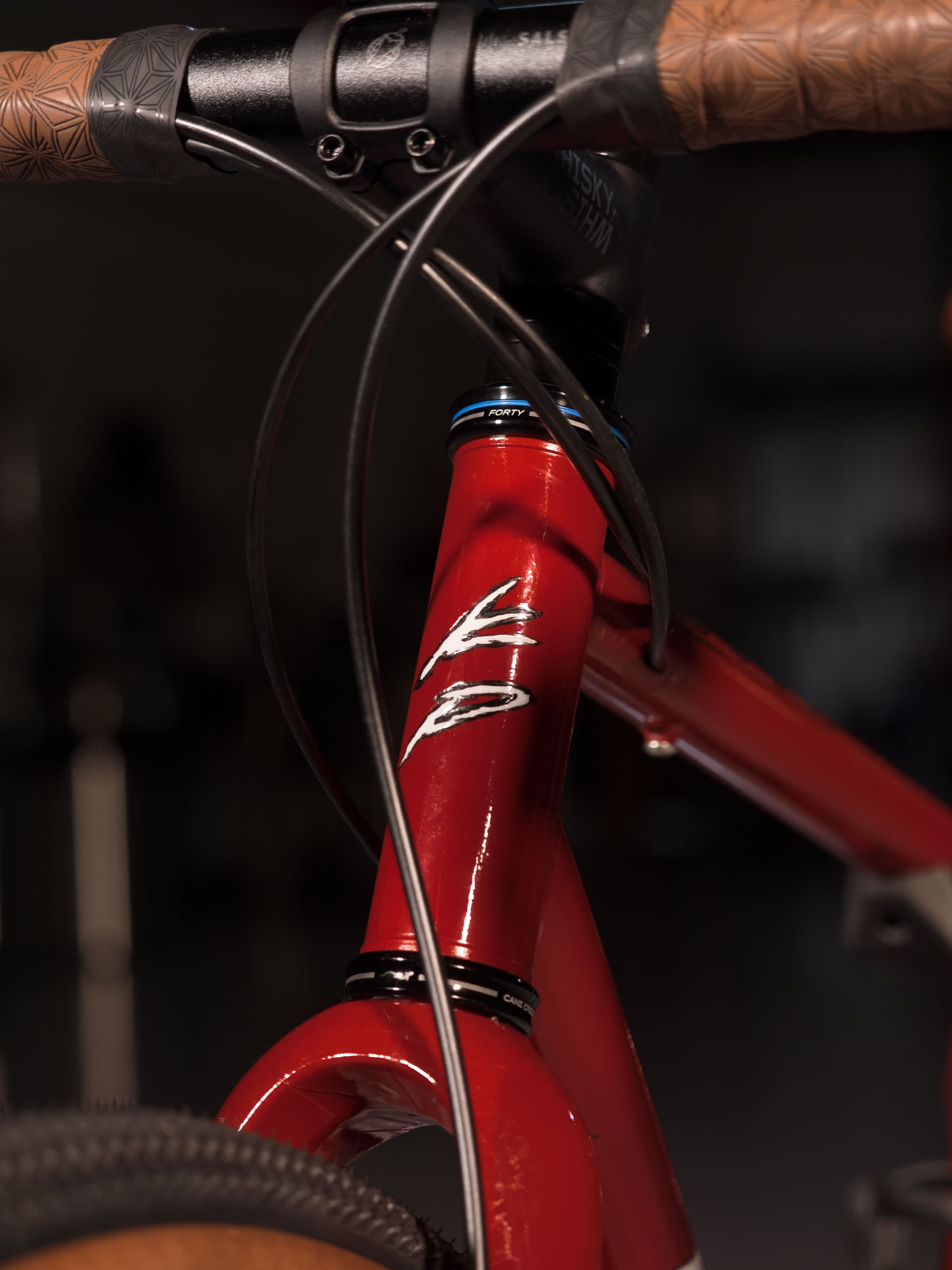
There is a bit of foreshadowing in this image. In January of 2023 I bought a sweet 50W JPT fiber laser engraver and this changed the game a bit. I realized I could possibly engrave head tube badges similar to the etched ones of 44 bikes. The badges shown above are 0.025" 6061 Al. The badges were engraved and cut out with the fiber laser. They were then painted with left over black paint from spray.bike and were sanded to reveal the metal on the outer surfaces. After that they were bent in a 3D printed fixture to wrap around the head tube.
I tried a few head tube badge materials but ended up preferring this 304ss badge with a worn look to it.

Somewhere down the road I also made a frame bag out of materials leftover from one of my previous ventures. Photo taken in Newmarket, NH right outside the old Independent Fabrication mill building.
Thanks for checking out this build and I appreciate you making it this far into the post. Overall the bike rides pretty great and I haven’t had any significant issues with it so far. Since the geo was based off a diverge with a 51mm offset and purchased a whisky fork with a 45mm offset, the trail is a bit excessive and the steering suffers a bit, but not enough for me to complain.