Hi,
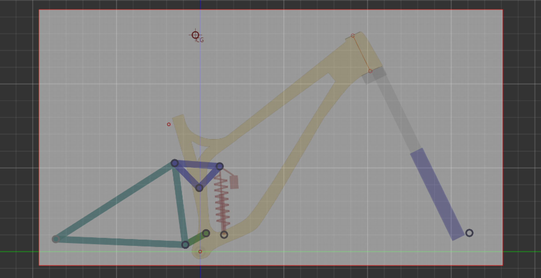
I have a design for a full-sus in Linkage that I’d like to transfer onto a sketch in Fusion360. If anybody has experience doing this and would be willing to share their process, please do! I’m very new to this and it would help a lot.
Here’s how my process has been so far:
Import image of my design from Linkage into Fusion360 as a canvas
…and that’s it. If anyone would like to share any advice at all, please do. I would especially love to know how I can make a rear triangle, get bearing tolerances right, turn this into a technical drawing, and conduct structural analysis.
Thanks for the help, Daniel! I’m thinking of using Enduro 3802 LLU MAX Es, which have an Inner Diameter x Outer Diameter x Width of 15 x 24 x 7/10 (mm). These are the same bearings that Santa Cruz and Pivot use.
I searched online for how to design a bearing seat, and what I found was very hard to understand. I’ll continue to try my best to decode them, but please let me know if you have any advice relating to designing a bearing seat - I would really appreciate it!
When you say pivot hardware, I’m assuming that you’re referring to pivot axle kits like this. If I design linkages that have the same width as, say, Santa Cruz’s or Pivot’s, would it theoretically be possible to mount their pivot hardware onto my design?
Thanks for the help again, Daniel. I’ll be sure to try these solutions and also look around some more. This forum’s been a big help and I truly appreciate you launching it. I’ll be sure to tell any of my friends interested in framebuilding to check it out!
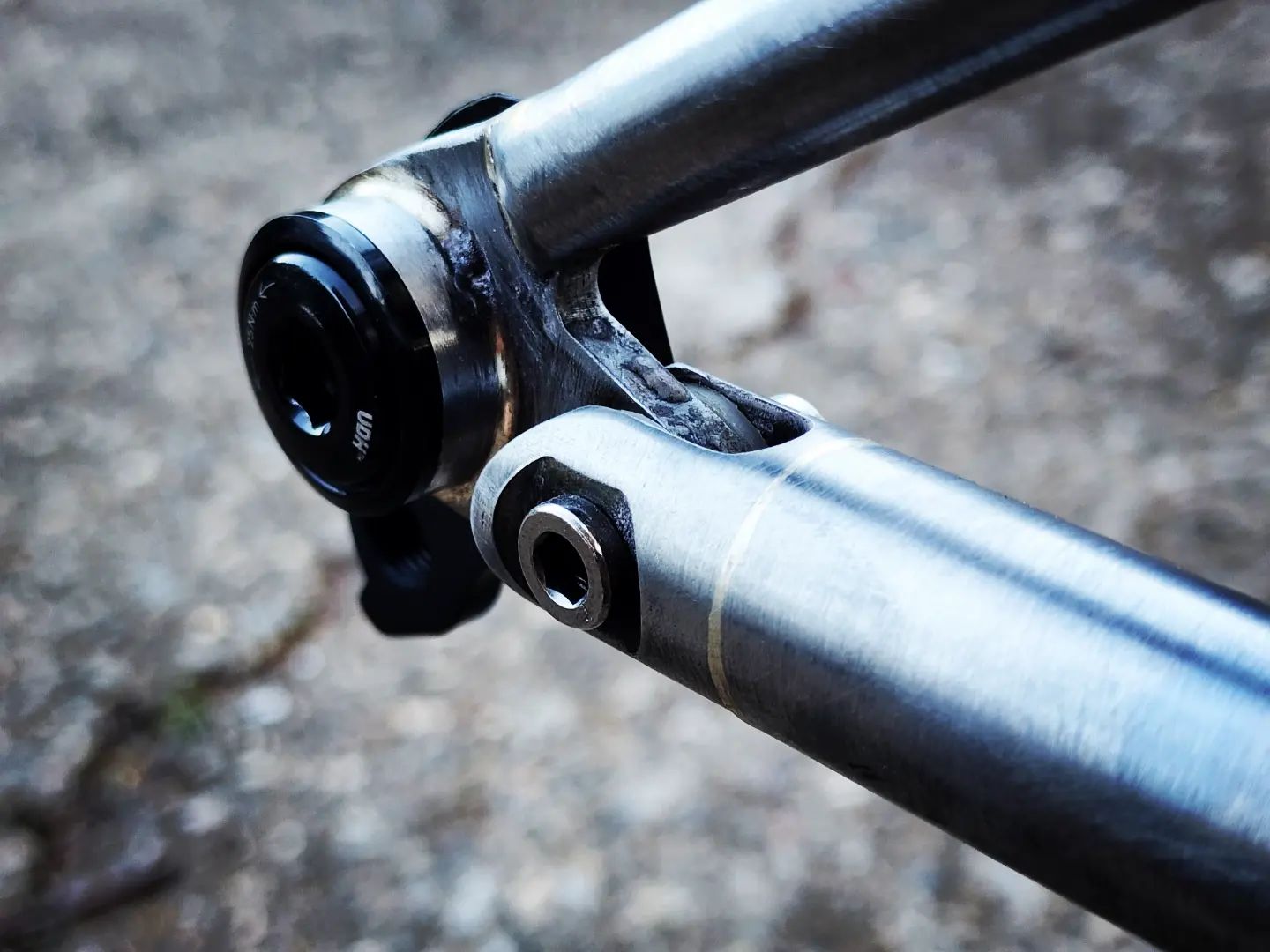
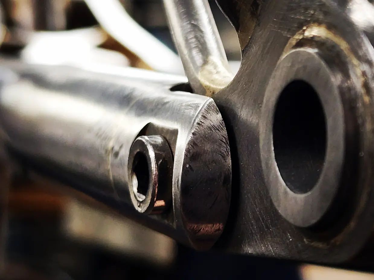
I used a pinch bolt setup on my single pivot build, and it’s worked great. For a bearing seat, you need one hole that is big enough for the entire bearing to press into, with a smaller hole keeping it in phase. The smaller hole should catch the lip of the outer bearing race, but not contact the seals/inner race. When designing mine, I looked at the exploded views that most bike companies put out in bearing service manuals.
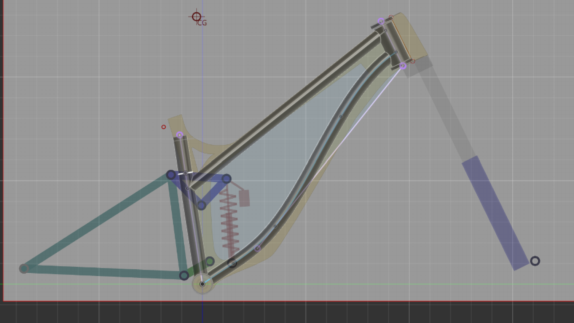
I’ve found exporting the linkage file to DXF, which I then open in Fusion to be my preferred workflow. There is still some time spent deleting extra lines etc, and the file format is not as fast as fusion files so on slower computers it could be annoying, but I find it gives some ease of mind and is faster for me than deriving each dimension by the measurement tool in Linkage. It allows export at various travel positions too, so checking for design clearance at bottom out without making a moving model is pretty quick.
For bearing seats/pivot designs:
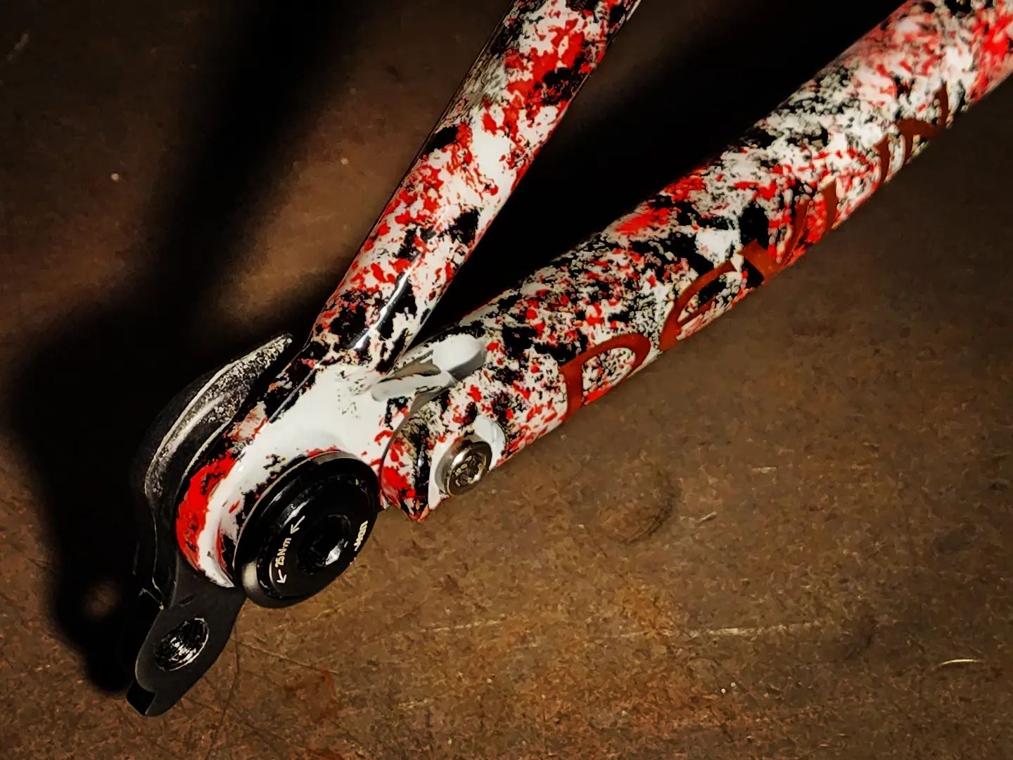
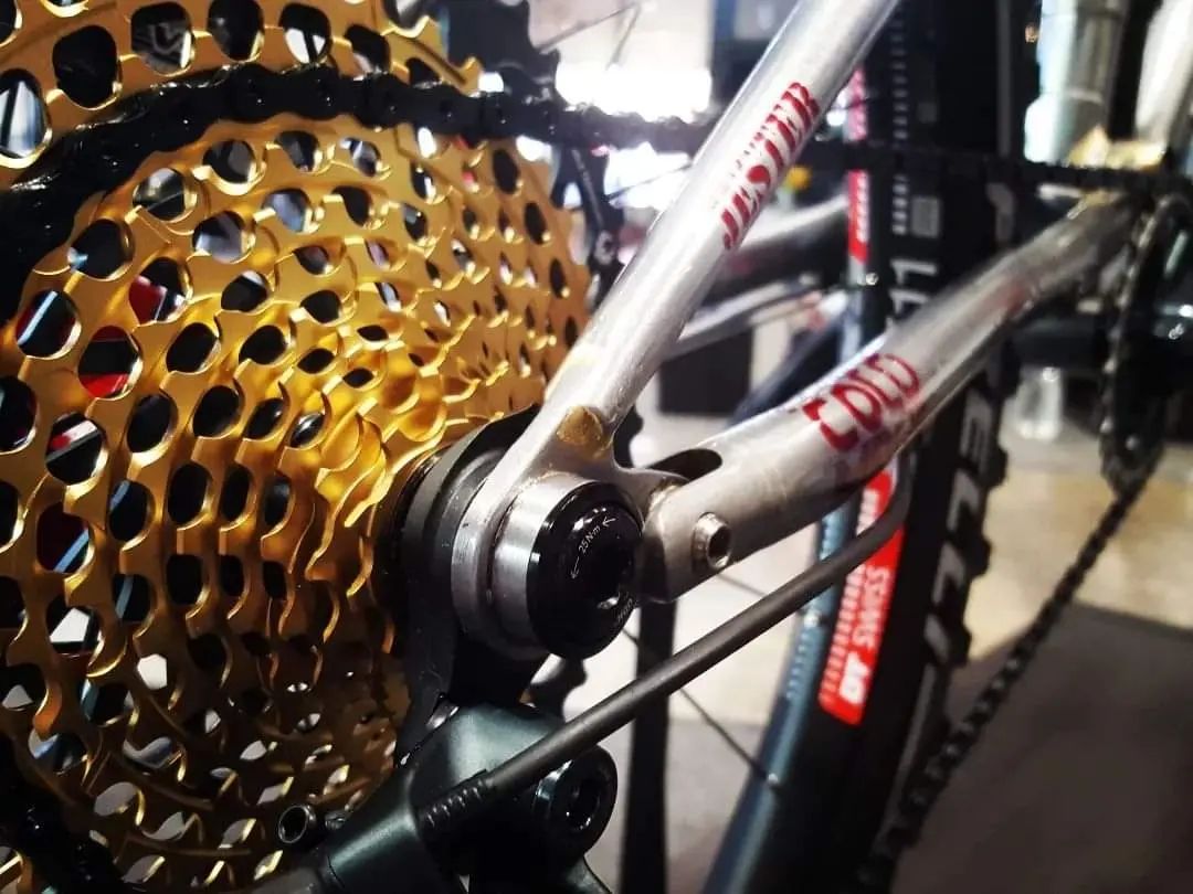
I have used a couple different designs, and none of them are particularly quick to fabricate imo, as there are always a lot of parts. If you have access and your design allows you to use an axle kit, I’d say that is the easiest route. On the types of bearings typically used, the ideal is to have no side load, but also no play. This would require precise matches in dimension of the bearing housing as well as the spacer, but depending on the leverage of any particular pivot it matters more or less. I’d say it is less critical than I thought it would be. I have typically used about a 3thousands interference fit on my bearings, and then have not had to use any sort of bearing retention, like a c-clip or a lock-nut. On a single pivot point design it would probably be more important.
One thing I’ve had to account for after the fact a couple times is remembering that all bearing surfaces need a spacer or a standoff, at least if the mounting point is larger than the center ring of the bearing. So that needs to be accounted for when designing widths of bearings seats, bolt lengths etc, and is much easier to do before you weld them to the frame haha.
Thanks! I appreciate the in-depth answer. And sorry for the late reply - this thread’s gone kinda dead because of how inactive I’ve been. Life has been really busy lately. It seems like I won’t be able to make my bike for the foreseeable future, but I’ll keep this advice handy for when the time comes!
BTW, Isak, thanks for building your bike. It was one of my inspirations for getting started with this project.
Speaking of full suspension, any of you used a clevis type of arrangement for pivots at the rocker and dropouts? Have you made them yourself or found an existing part?
I’d like to use Igus bushings and it seem to be the best way to do it.
Yep, at teh horst pivot as it only articulates about 4.7 degrees. The rocker needs bearings as it goes through 35-65 degrees. Currently using road caliper barrel nuts and M6 bolts with machined delrin bushes. I do have plans of using shock pivot hardware for this though. ie. the Igus bushes and anodised spacer.
Hey! I just stumbled on this thread again. I’ve spent the last four months designing and building a full-suspension linkage bike. All of the bearings are pressed into machined aluminum parts until they rest up against a lip. then there are spacers that ensure the bolts are only applying pressure to the inner race of the bearings. I’m not an engineer, and probably broke some rules while designing this bike, but in a few weeks when the project is over I’ll post some details of that stuff if it’s helpful.