Strength is just one component.
Has anyone in the US used the supplier ProtoTi for 316L SLM parts? Craftcloud is recommending them. If you’ve used them I’m curious what the tariff was and what your experience was.
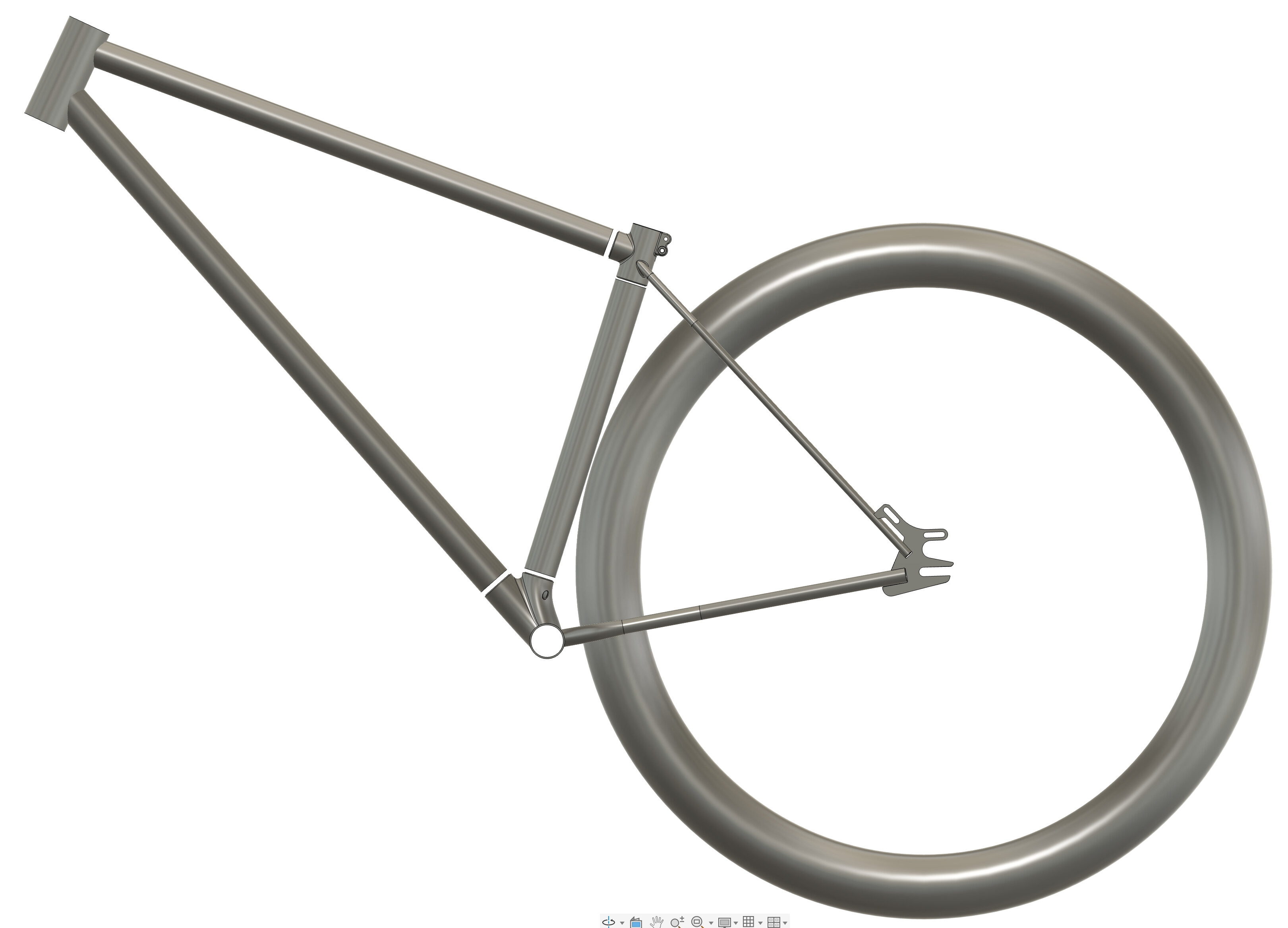
I’m taking the leap into printed parts, hoping for some feedback from those who have some experience. I’m planning on 316L, glass bead blasted, magnetic polished, heat treated. Probably using Protosoon unless anyone has a better recommendation.
My goal is cutting down on fabrication time because I hand cut/file/grind all joints.
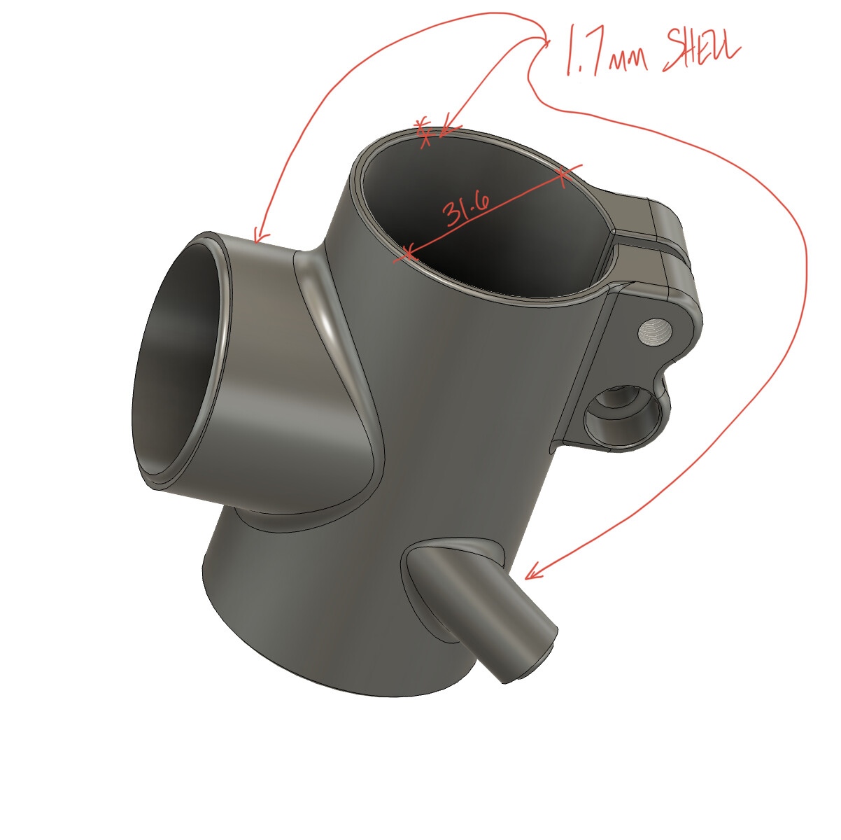
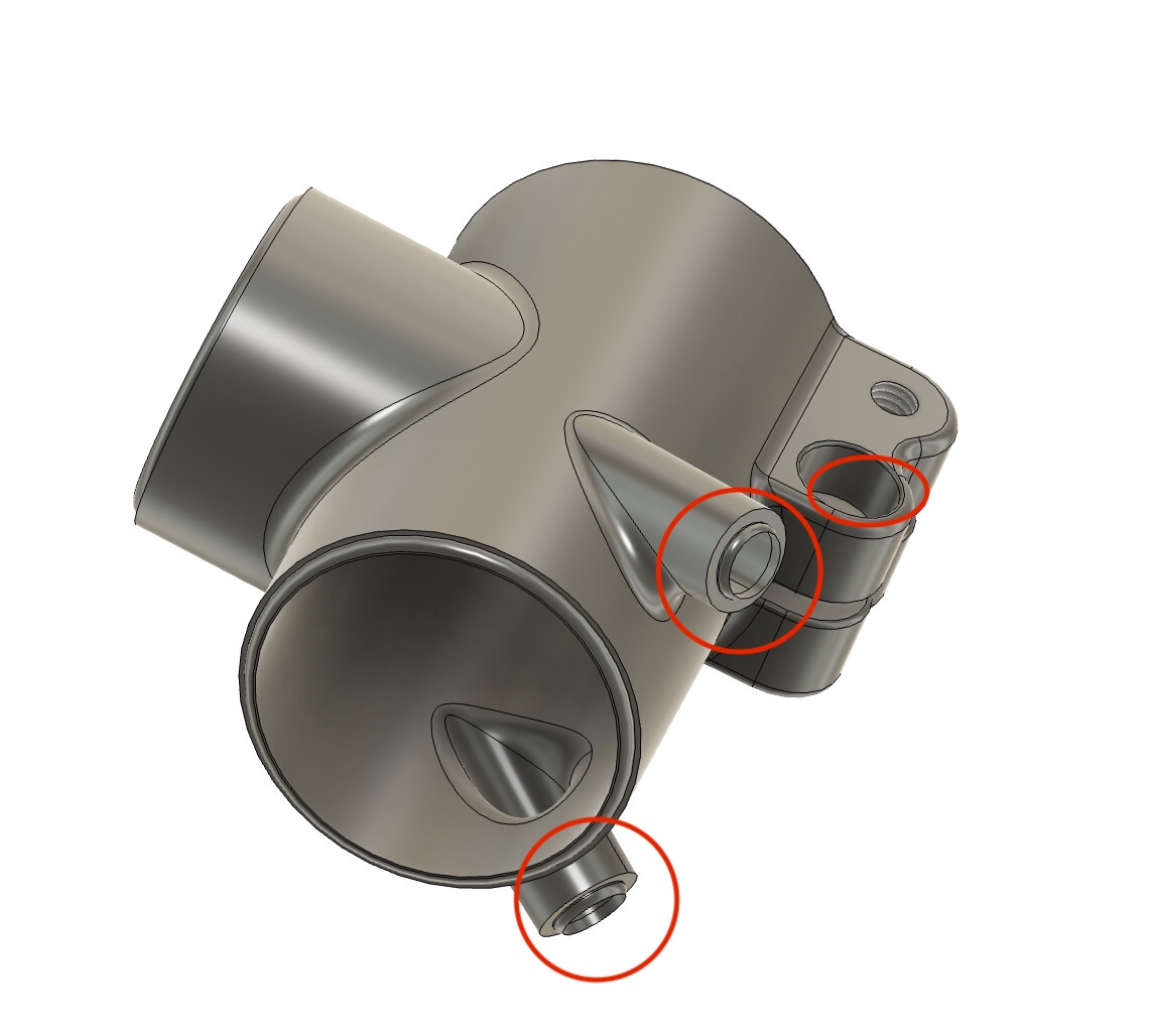
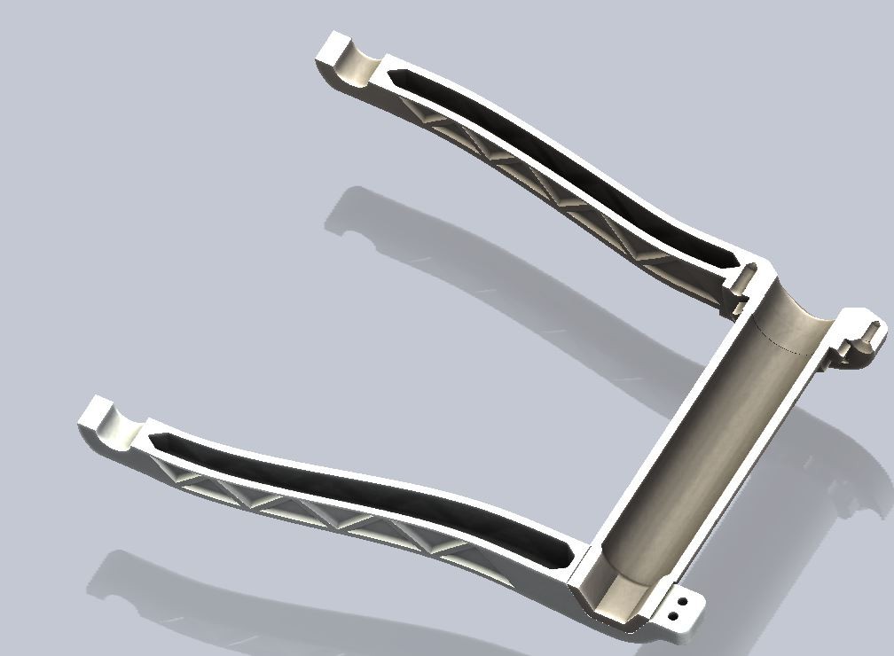
Seat Cluster Yoke:
1.7mm walls
31.6 for the seat post - should I make this smaller to allow for reaming to make up for any distortion?

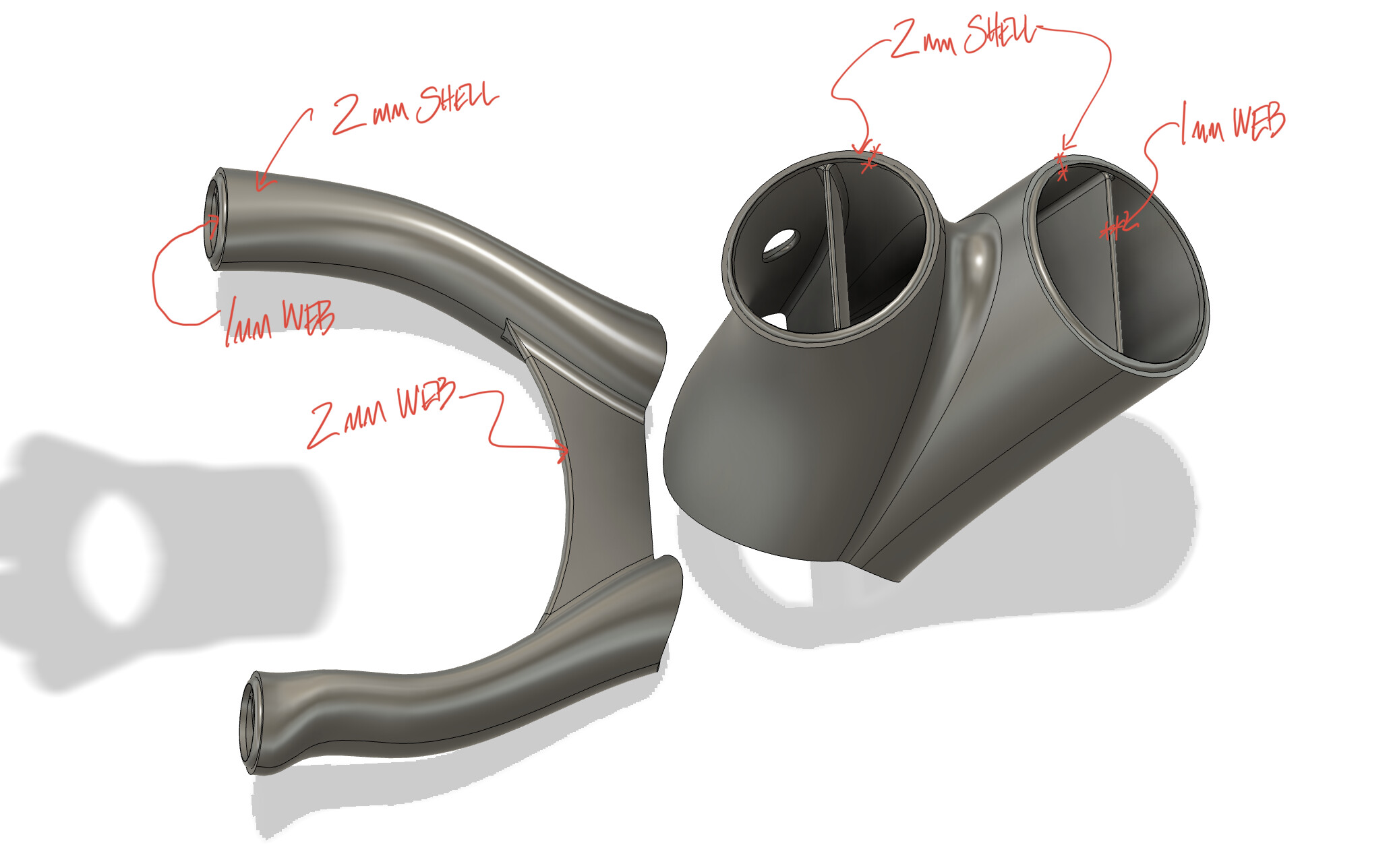
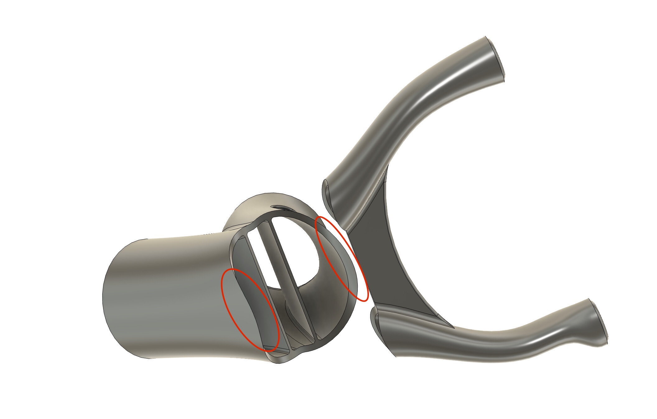
Seat tube/Down tube yoke:
2mm walls
1mm web
Hole for dropper cable - is this a bad idea?
Chainstay yoke:
2mm walls
1mm web
2 Likes
I know nothing except it looks good
1 Like
Looks really nice! I have only done two frames with 316L printed pieces in them so I am not an expert. In my opinion, you can reduce your wall thicknesses by 0.2-0.3mm across the board (webs can stay the same) and that’s still pretty conservative. If you are tigging this I would add maybe a couple more mm of the sleeve where the tubes join, just to give the heat a little more space to go and the overlap offers a little peace of mind. Your post treatment options are wise and everything looks great, but again I’m just an amateur. There are a lot more experienced people on here that I would listen to over me ![]()
1 Like
I’m also no expert, but I do know that 3D printing does not like coming to a thin sharp point. I’d revise your design in these areas to either add a radius or adjust the design to limit these thin points. In addition to increasing the overlap on the printed part and the tube like was suggested above. If you want to save money, you can always use an off the shelf seat binder, or weld one on. Printing the seat binder is going to add some cost since the prints are usually quoted by weight. Since it’s a 3D print, you could also just print a small guide for the dropper post into the part. Overall the design looks awesome.
Edit: I think with the heat treating and post processing of many 3D printed metals, it can create a hard surface that can be difficult to work with (tapping, reaming). I have heard it’s really difficult with titanium, but I’m not sure how difficult it is with Stainless.
2 Likes
Great, I’ll drop it a bit.
I was avoiding the longer sleeve so I would have more adjustment wiggle room in the overall geometry. I didn’t think about heat, that makes sense.
Makes sense, I’ll get rid of the sharps.
My original plan was to copy @Daniel_Y’s top tube yoke, but after pricing the parts, it’s barely more cost to print the whole thing compared to buying the seat tube collar and binders and printing the yoke.
For reference the part cost quotes from Protosoon (these will go down a bit when I reduce wall thickness)
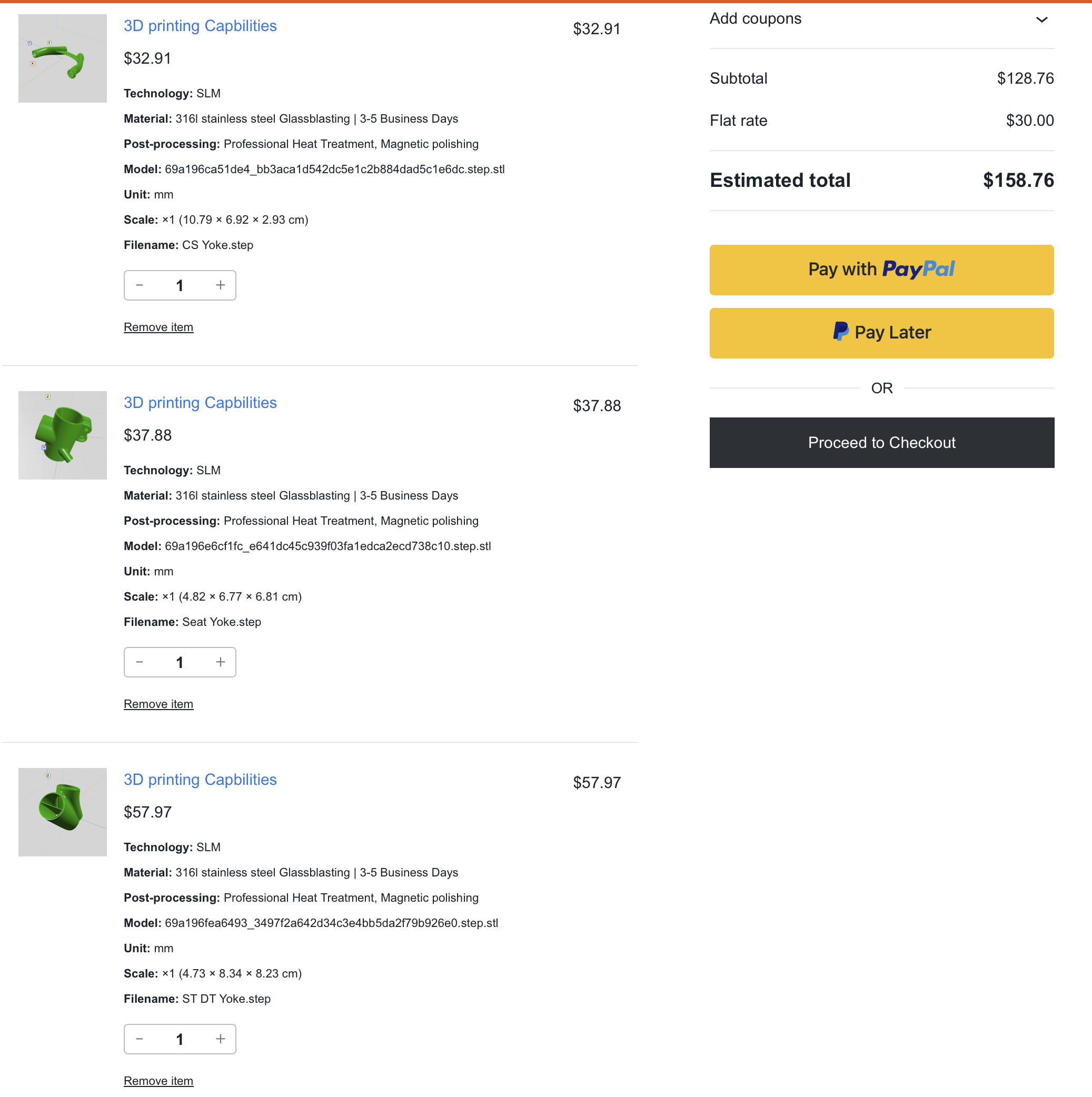
:
3 Likes
Nice, looks good. Also as for your seat tube, I’ve never printed one so I haven’t had to ream one but I have done several bearing seats and pivot holes and I I have just gone 0.3mm undersized on the diameters and have had good luck. However I am machining all those on a mill with a reamer or boring bar. I haven’t done any by hand but I assume it would be a similar experience. I know the holes are not perfectly round without the machining.
4 Likes
I only have one piece of 3D modelling advice: use fillets based on “chord length” instead of a normal constant radius. It will look even nicer and is better at avoiding stress risers ![]()
7 Likes
Yep, I’ve printed a few seat tube clusters like this and need to ream all of them. I print it only ever-so-slightly undersized (0.2mm) in the diameter and ream to fit once I get them. I 3D print a jig that’s designed to clamp around the outside of the part so I can do the rougher reaming in my mill before welding on, then do a final ream to fit once joined to the actual tube after welding.
2 Likes
gschwell great looking parts.
One option you might consider is replacing the two threaded portions of the seat cluster with hexagonal recesses sized to hold captive nuts.
Such an approach may lower the print weight/cost by a small margin, sidestep any issues or difficulty in printing or tapping the heat treated and printed material, as well as make the threads a sacrificial and rather easily replaceable part should they ever get buggered over the frame’s life.
Just a thought.
Please keep us posted on the progress as well as the costs of the prints if you’re willing; I’d love to see more data points on the timeline/price/shipping/tariffs costs parts like this end up with.
3 Likes
About heat treatment and hardness. Here’s a quick rundown of some common alloys folks are using on bike stuff:
- 316L: More heat generally means softer material, so generally speaking, ‘heat treatment’ of 316L will make it more ductile, and easier to cut in most circumstances.
- Ti64: Properly stress relieved or annealed, it will make it EASIER to cut/tap than ‘as-printed’. However, if it’s heat treated improperly (too hot, or in an oxygen or nitrogen environment) the results may be unpredictable and undesirable in all sorts of ways. Titanium is complicated. I advise this stuff MUST be heat treated, but it MUST be done properly. If not… it may crack, warp, or just cause you trouble.
- 17-4: Annealed or ‘stress relieved’ (condition A) will be easier to cut than as-printed or hardened, but has the least desirable performance mechanically. 17-4 should be used either as-printed or solution annealed+age hardened. I don’t recommend this alloy for bikes, though lots of nice bikes have been make with it successfully.
- AlSi10Mg: This is the most common 3D printed aluminum. If you are getting printed aluminum- it’s almost certainly this stuff. It is ‘safe’ in any heat treatment condition, but properties can change significantly depending on what is done. Here is a summary:
- As-printed: highest strength it’ll ever be, but often brittle. Properties dependent on specific printer settings used to make it with. Highest anisotropy. Unpredictable.
- Low temp stress relief (~170-220C): keeps most strength but becomes slightly less brittle. Gains some fatigue life. ~40ksi yield.
- Moderate temp stress relief (~250-350C): Gains some usable ductility (maybe 10% elongation) but loses significant yield strength). ~30ksi yield
- T6: just don’t do this. Its expensive and makes parts distort. Does give probably the best overall balance of properties, but at a cost.
6 Likes
Hi Hank,
I’m assuming that AlSi10Mg is readily weldable, since the printing process is essentially welding, but all the applications I have seen in the bike world seem to be a bonded applications.
Do you have any info on the suitability/compatibility/treatment of AlSi10Mg parts for welding to 7005 and 6061 tubing alloys?
Also, I have been looking at the metallurgy of Scalmalloy as a possible alternative to AlSi10Mg (now that a few of the Chinese printing houses finally have access to it), but no info on its inclusion in welded structures.
All the best,
Dan Chambers
Hi Dan,
I am not an expert on ‘conventional’ (non LPBF) welding- but here’s what I know!
i think a lot of folks are bonding printed parts is because they don’t have the ability to weld! That honestly why I bonded my frame… Furthermore the tech gives you the option of making all of the bonded joint shapes pretty easily to make things bonded. Lastly, as you probably know most aluminum should be heat treated after welding, so if you are making 1-off printed lugged frames, that’s an expensive step. You can avoid that heat treatment step if you bond. For me- bonding is just a shortcut…
For an example of someone welding AM aluminum to non-AM material- check out these Intense frames. I believe the AM material they used is 6060-Ram2 from Elementum3D. That alloy is ‘regular’ 6061 with a bit of pixie dust mixed in to keep if from cracking during print.
AlSi10Mg: AlSi10Mg is weldable, but appropriate filler needs to be used. It needs a high silicon content filler. I think materals and methods used for aluminum castings has some similarity, as cast alloy like F356 / F357 is very similar in composition to AlSi10Mg.
Scalmalloy: This stuff is the best. Love it. Its my favorite printed alloy. Strong, fatigue resistant, relatively high ductility, and east to heat treat. I would use it for all of my aluminum printed projects but I have less access to it than AlSi10Mg. Fun fact- my current crankset is made of this alloy. I printed them ~2 years back. I have no experience welding it conventionally, but I suspect it should be possible. My guess is this would be easier to weld that AlSi10Mg but this is based on a hunch.
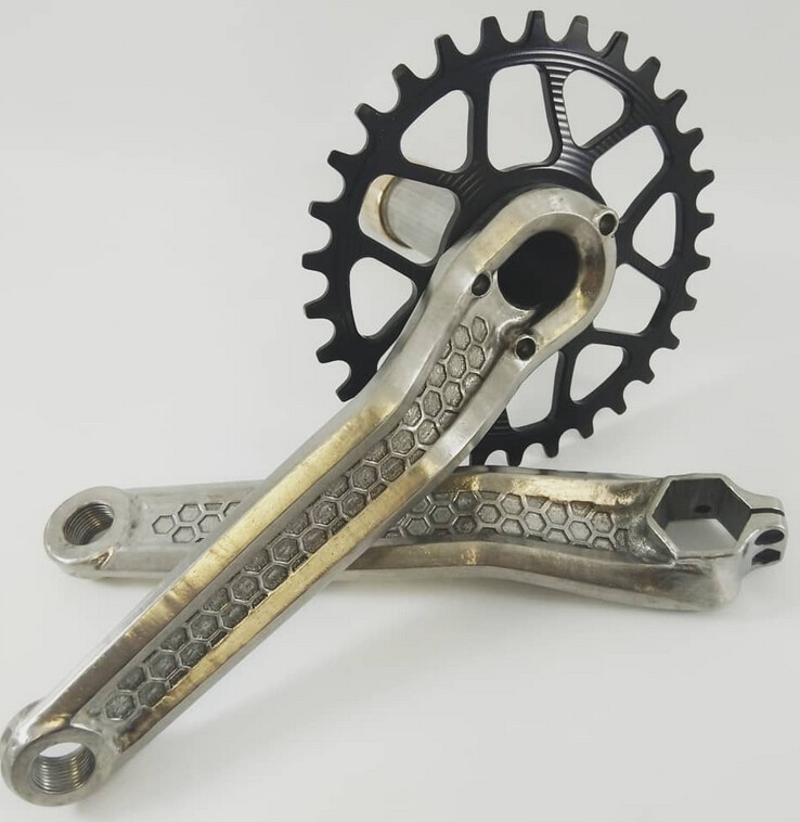
My scalmalloy cranks:
6 Likes
Tell us more about the cranks…
1 Like
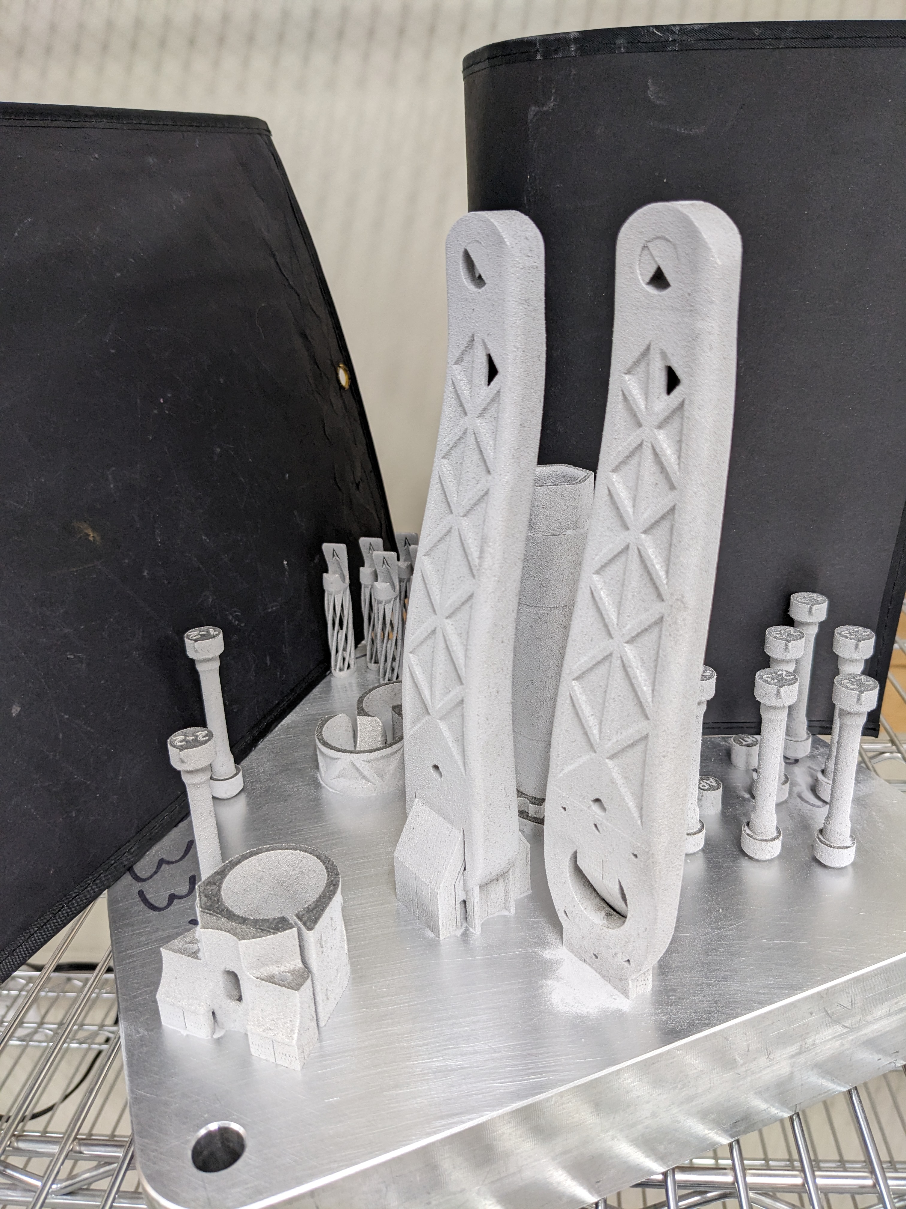
@gschwell ok- scalmalloy cranks. Here’s the download:
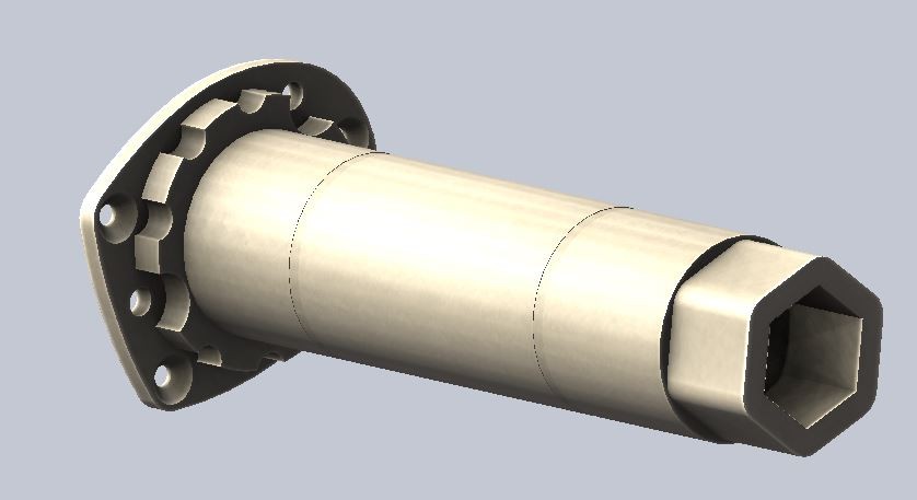
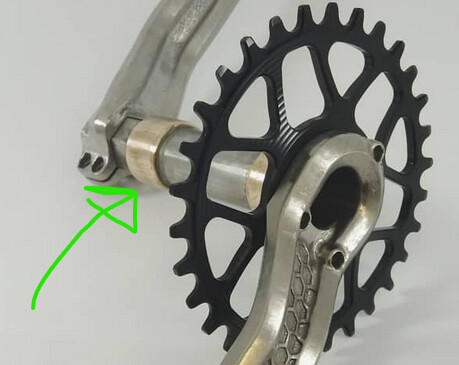
Printed using a LPBF machine, specifically a SLM 280HL. They are designed to avoid the need for finish-machining. As such I made them 3-piece with a separate spindle. The spindle is bolted to the driveside crank, and the chainring bolts also double as additional bolts to clamp the spindle to the crank arm!
- Qfactor: 168mm
- spindle diameter: 30mm
- chainring interface: Xsync 2, 3 bolt
- arm length: 165mm
- weight (cranks+spindle only+hardware): 375g

I printed these back in almost 3 years ago but haven’t put many miles on them. I also made some Ti64 cranks of a different design and those have been my go-to set. The scalmalloy set was actually on my neighhood dad-bike until last month!
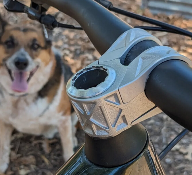
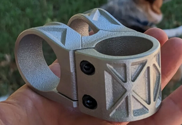
See that there is also a stem on that build plate next to the cranks? I’ve been riding that on my mountain bike for ~2.5 years.
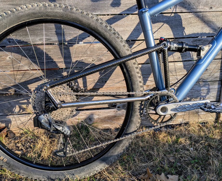
Ti cranks below. I made those over 5 years ago. Still going strong, though the design is inferior in a bunch of ways to the scalmalloy set. For those I used press-fit brass bushings on the spindle to get a precision interface to the bottom bracket! I heated them up with a torch, and slid them onto a cold spindle to try and get an interference fit. It’s actually worked great.
7 Likes
That’s really cool. You say on the scalmalloy set that there was no need for any machining. Not even a bearing seat on the spindle?
Looks like Scalmalloy is essentially a 5*** series (Al-Mg) alloy, very similar to the 5356 filler rods recommended for 7005/7020.
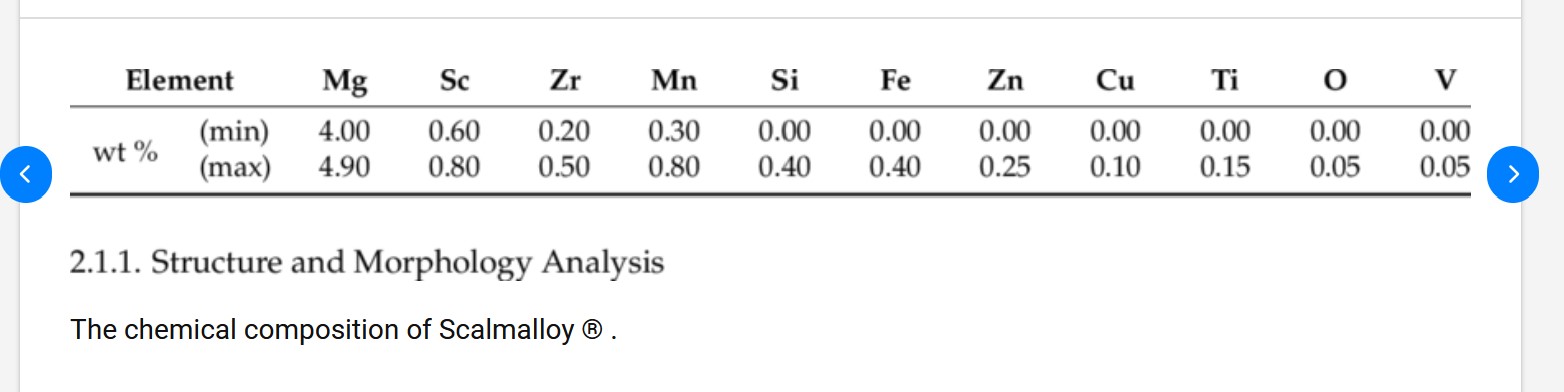
I found this on Metal Zenith:
”Welding Scalmalloy is feasible with TIG and MIG techniques when weld procedures control heat input and filler compatibility. Recommended filler alloys are typically Al-Mg-based or specially formulated Sc-containing fillers if available, to avoid large compositional mismatch and to maintain ductility in the joint. Weld heat-affected zones (HAZ) can exhibit softening if dispersoids coarsen or precipitate distributions are altered, so post-weld artificial aging or localized heat treatments are often used to restore properties. Hot-cracking risk is moderate; low copper and controlled silicon help reduce susceptibility compared to some Al-Zn alloys”
Which would suggest that indeed Scalmalloy is compatible with 7005/7020, preferably using the proprietary Scandium filler rods (I buy these from Dedacciai), or 5356 filler (Al-Mg), rather than the 4043 (Al-Si) that would be used on a 6*** series structure such as the Intense frame.
Followed with the usual post-weld ageing (Typically 6hrs @ 90C/200F then 4 Hrs @ 150C/350F) of the whole structure to restore the 7005 to T6 and add a little UTS and Yield back to the Scalmalloy.
All the best,
Dan Chambers
2 Likes
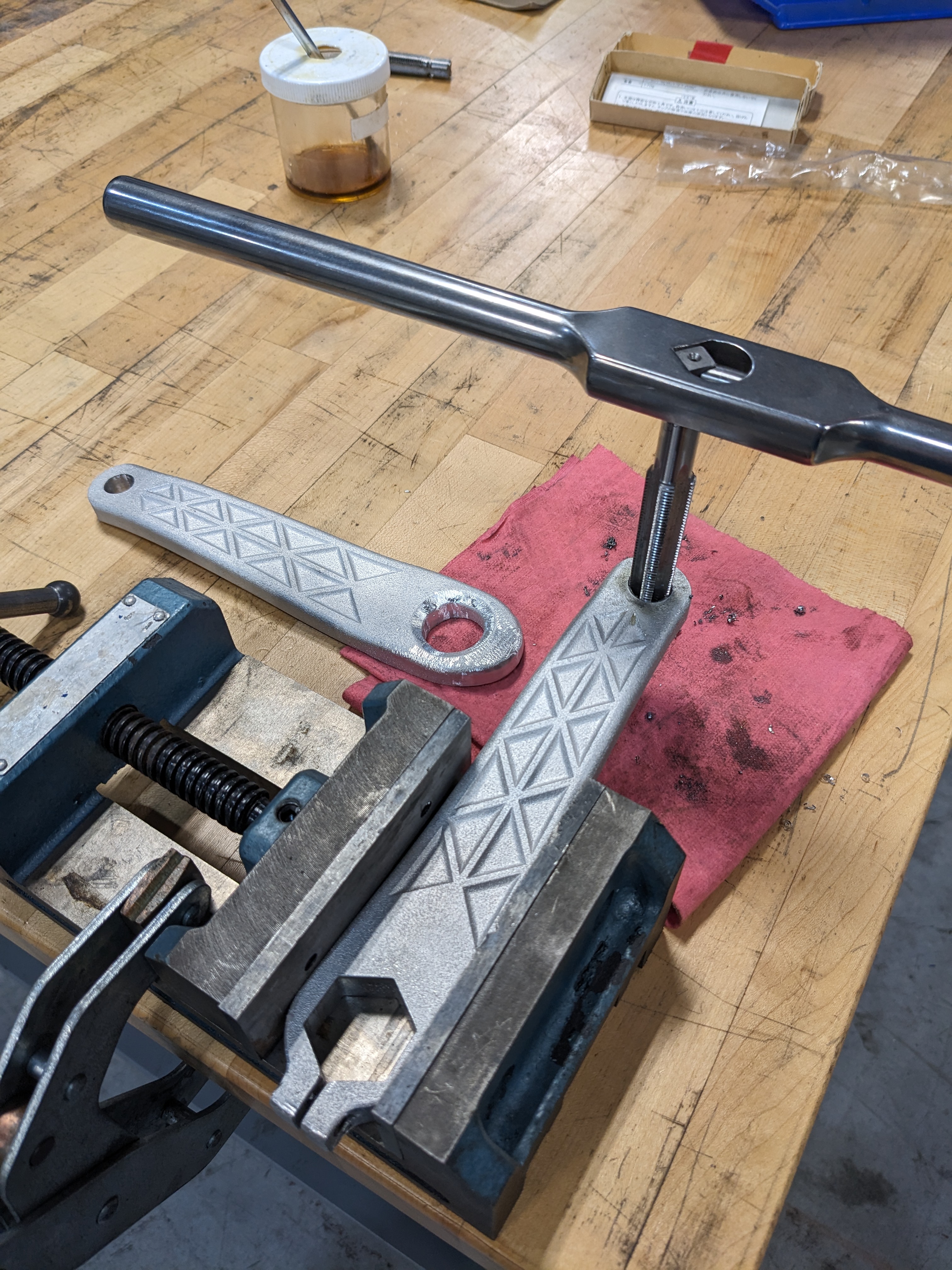
Indeed I did not use anything but hand tools to finish the scalmalloy crankset. To get the spindle to slip-fit to the bottom bracket I did something rather janky. I made a little adapter so I could spin it with a hand drill, and used sandpaper to “machine” the spindle to size. Is it perfect? Absolutely not, bit its good enough for my purposes!
For the record- I’ve made 2 cranksets, 4 stems, 2 saddles, 2 handlebars, a lugged full suspension frame, and all sorts of random accessories without any CNC. At times its been painful TBH, particularly tapping threads in Ti by hand.
4 Likes
Great work, thanks for the info.