That seems a bit low. I would check the exported scaling of that part. I would expect it to cost ~$40-50.
There is also the heat treat and shipping that adds to the cost.
That seems a bit low. I would check the exported scaling of that part. I would expect it to cost ~$40-50.
There is also the heat treat and shipping that adds to the cost.
Thanks all. I just logged back in with the intention of ordering a few just to see and after uploading the exact same step file, the price has jumped up to $32 which seems a bit more sensible. I’m not sure what the difference was, it all looks the same to me but I may have missed something or done something silly. The calculated weight is the same and the material/finishing is the same but hey-ho it is what it is. $32 is still way lower than I expected so I’m keen to see if I can work this into my process.
Thanks for the insight and advice, Sean!
Good call on the galleries - I created internal holes on my parts to allow for backpurging; it seems like a secondary benefit is allowing the excess powder to empty out of the internal cavities.
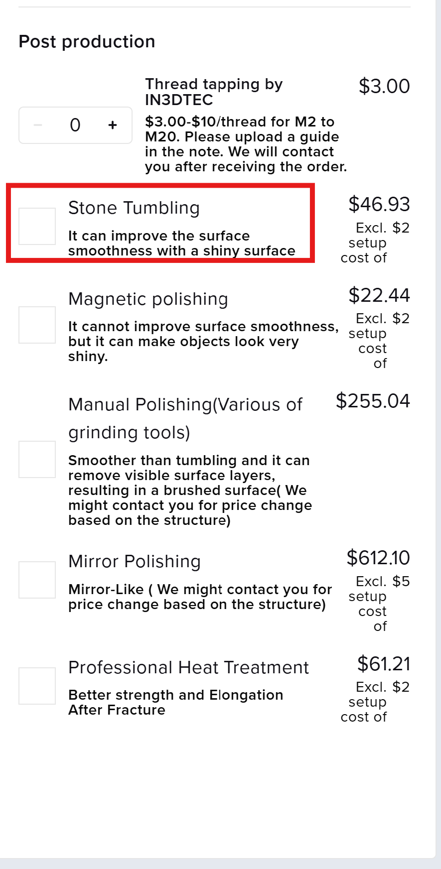
I did request “stone tumbling” (screenshot attached) but suspect In3Dtec used magnetic polishing instead. Here’s the response I got from their customer support:
Thanks for reaching out and let us know the issue.
We were concerned that ceramic and stone debris might get lodged inside the pipe, making it difficult to remove. To address this, we used a cardboard box as a temporary barrier during the grinding process.
However, before the shipping, our grinding team accidentally forgot to remove it.
I have already spoken with our team to ensure this oversight doesn’t happen again. Please accept our sincere apologies for the inconvenience caused, and thank you for bringing this to our attention. Your understanding means a lot to us.
Not sure how common this issue is across other customer parts/geometries, and if any process changes were implemented. I don’t think I’ll request any post-processing services for future parts aside from sandblast/beadblast.
Interesting. I dont recall seeing those options when ordering before. I will dig deeper next batch.
Sweet that’s also what I’ve been using for the designs of my parts after some research ![]()
I don’t know how to delete this post so as a mod, I’m writing over it. - Coco
hi John, are you a bot?
Heyo,
Since I’m in-between jobs I’m spending a bit of time looking into 3D printing.
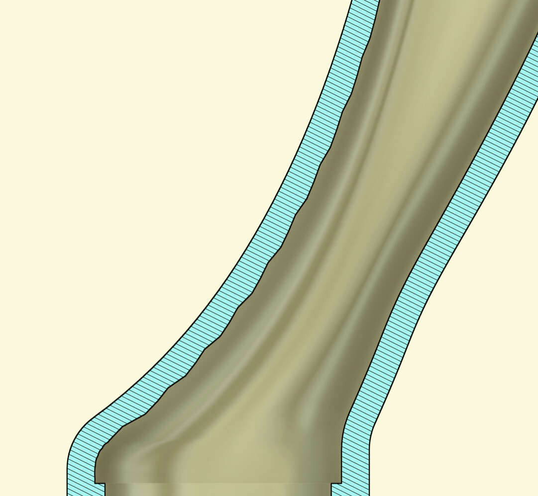
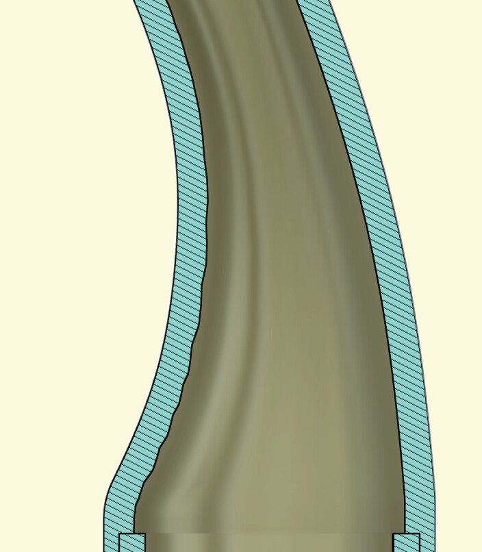
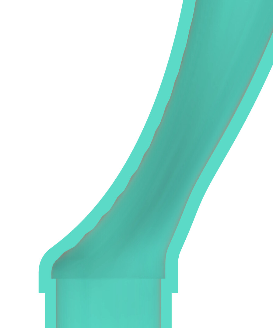
I’m a little bit into designing a yoke and noticed jagged edges on the inside when I shelled it.
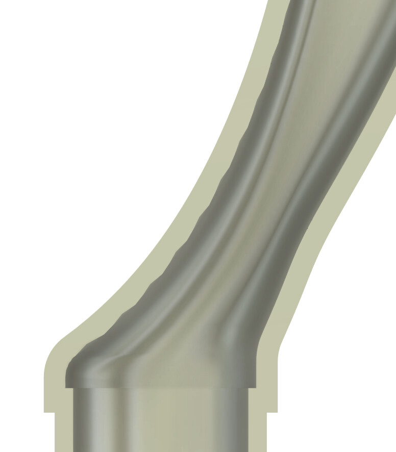
I first noticed it in section view/analysis. Wasn’t sure if it’s just a result of that so I split the body and took a look.
Is this just an artifact of the shelling? Something I need to be concerned about?
(Ignore the right angles, at the yoke/CS junction. I know those need to be addressed)
Thanks
That’s a strange artefact.
I don’t use Fusion, but if the shell function is anything like in SolidWorks, then it can be very temperamental. I’ve never seen the shell command create a jagged surface like that before.
Have you tried playing aorund with the wall thickness?
In SW, the shell command is very sensitive to the curvature of the outer surface. Sometimes it errors out if the shelling essentially eliminates a radiused corner. I.e. if the outside radius of a corner is 2mm and you’re trying to make a shell with 2mm or more wall thickness.
You’ve got a pretty flowing design there, I’m assuming they’re achieved via lofts and guide rails, and I suspect that maybe something is happening with the inner surface if the curvature of the outer surface is not ideal. Have you checked the curvature of the outside surface before shelling? The curvature combs and zebra stripes tools come in handy for that.
Hmm I’ve seen that happen before. Is the part solid modelled or surfaced?
I saw that while doing LOFT in Fusion. Now my preferred method is to create a full solid, delete some faces to have a surface and then thicken the surface with desired thickness for 3D printing. I found it gives me more control on this specially because I also do some Fillets on the surface before in order to have more smooth.
there’s a thread on the Autodesk forum where someone has not-dissimilar issues and ultimately resolves them:
the issues in that case were caused by “shelling” smooth but what I’m going to call “non-uniform” surfaces on a sculpt body, and fixed on video by another user here;
if you’re struggling, sharing a file might let one of the fusion-bike-gurus here open it, and have a sniff around to find a solution for you.
That’s a great vid @crowe-molybdenum ! I recently had the same issue but on the outside of a loft. It appeared whether I created the loft using solid modelling or surface modelling. It showed up on the section analysis as a badly damaged wall, but whenever I ran surface analysis, zebra, draft etc it disappeared! I also scaled the section up and printed on my 3D printer and it was fine. It’s now with Ram3D and they say the file is fine too! Not sure if it’s just some anomaly with the project when it’s being worked on. I also exported the part as a component as a .Step file and when I opened that exported file up, the interference was no longer visible on the section analysis! Have you tried that @ElysianBikeCo ,export the part then bring in the exported file again? Might be a way of double checking?
Last night I hit up a friend with SolidWorks. Sent her a STEP file with bodies that were both solid and shelled. She couldn’t find any issues with them. She also couldn’t find any issues when she recreated them from scratch.
I did exactly what you suggested and brought the STEP files into F360 for review. No jagged edges. I guess the behavior is a result of the F360 format?
Thanks for the responses ya’ll.
Why put a link to a painting business in your reply in this thread?
@Daniel_Y I believe we may have a bot in here.
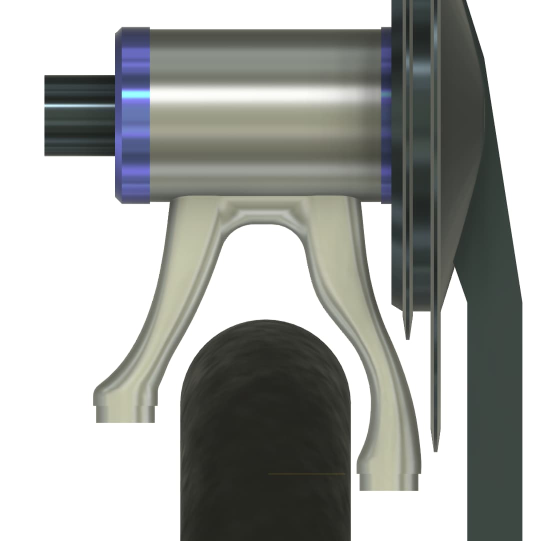
Yoke is looking clean!
I think it’s always a good idea to do a standard FDM 3D printed prototype to confirm your designs before moving to metal. It’s much cheaper and very easy to do some section prints to confirm surfaces are as expected.
I am trying to get some quotes for a 3DP part and I am confused on the pricing:
PCBWay quoted me ~100 for 10 pieces
Xometry quoted me ~1800 for 10 pieces
I have tried another one and it was about ~220$ per piece.
Why such difference?
What service in 2026 is a good compromise in quality and cost?
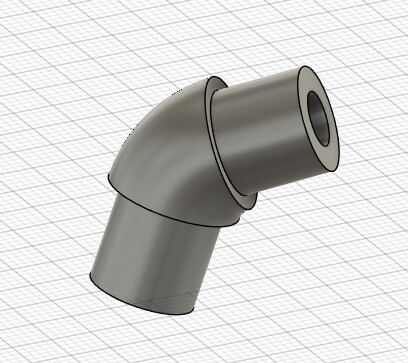
Here is the part, it’s a connector between two tubes that I was thinking of brazing in place. tubes are 0.625in so it’s a “small” part.
@Matt- for printed parts, especially metal using Laser Powder Bed Fusion, I think there is a gulf of pricing between ‘rapid prototype’ service bureaus, and those which are geared toward producing parts for rigorous applications and industries.
Secondarily, printing services setup to work business-to-business rather than to consumers, are going to generally be more pricey.
A shop setup to ‘print-and-strip’ as fast and cheap as possible generally will struggle to also meet requirements of aerospace/defense/medical/energy ect. For that matter, even consumer goods which might have LIABILITY if something fails end up being significantly more $$ to make. Printing services treating the material “rigorously” for quality, traceability, repeatability ect are probably going to be more expensive.
If a company is setup to have every single part reviewed by engineering, planned by a project manager, have inspection plans made by a quality engineer, ect,ect. It adds up. All of that is needed if you are selling functional components to a rigorous industry.
About Xeometry and PCBWay
I believe Xeometry tries to do BOTH ‘rapid proto’ work and ‘rigorous. They have multiple ‘tracks’ of how parts are ordered and made. I haven’t used them myself, but I do wonder if there is a different quote tool you could use with them to see a lower price. I believe they print both in USA, and China, for example.
PCBWay is in China. Right now it seems like China is offering very significantly lower prices on metal printing than anywhere else.
I use protosoon for printing parts, good pricing and communications.
This is interesting, in particular the “Maraging Steel” option that seems to have a better strength than 316!