Yeah, absolutely trying to minimise the time to prep each part. Both in the physical effort and the time it takes. I want to ride bikes, not just make them. Haha
3 Likes
also to add, I am getting things like the BB threads and the main pivot machined in the bottom section of my frames. I could set up and do them both myself but the reasonable charge they ask is less than the time/cost it takes me to do and it’s bang on accurate. Plus the responsibility is on them to do the work. If I stuff it up I’m down a part and potential it’s a stop work. Once they send it out, it should be good to go. That is the only caveat, that their QA/QC is adequate. The last order I had came with two left rockers when I definitely sent left and right models. I ended up modifying those models anyway and getting them reprinted, which means their error is inconsequential at the end of the day.
4 Likes
To finish up the v2 story, here’s my analysis of the kinematics and comparison to v1.
I must say that if you haven’t made a full suspension bike with a gearbox and 24T chainring, the space is very limited and finding the optimal points is almost impossible. So if you think the kinematics are funky, I welcome you to try for yourself 
Overall, the v1 kinematics were fine, and I didn’t intend for the v2 to be that different. For the dual-link suspension, it just came out like this after the million iterations…
Also, I dropped the BB height on the v2 by 5mm, which leads to inevitable differences.
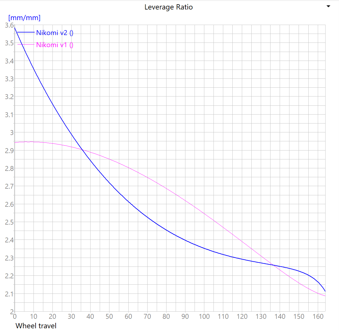
Leverage ratio: Yes, it’s pretty progressive, which by itself is OK. But yes, there is a “wall of support” somewhere after the mid-support area. What I thought that the high start ratio would do is be very supple in near the top-out (for example on a rooty trail where the rear tire is in the air occasionally), but that was surprisingly not that different. What I found was that how much the damping is affected also. So, when pedaling, the rebound is a bit wallowy, which could use more low-speed rebound. But on deeper hits you have too slow recover. So you are stuck with adjustment that is ok in the middle and sucks a bit on both ends. Of course with valving this could be made better, but I haven’t got into that.
For v3: Dial back for more linear curve.

Axle path: Pretty much the same. This is not a driving factor after all, but rather the outcome of anti-squat and leverage ratio etc.
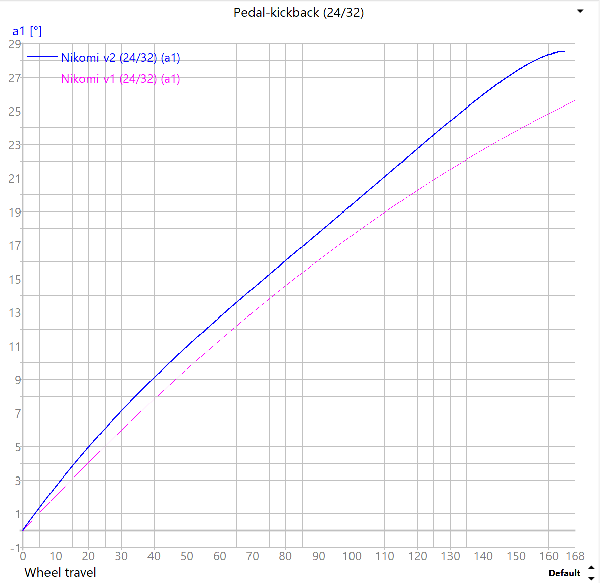
Pedal kickback: When I rode the v1 in chunky bikepark stuff, I was certain that most of the pedal-kickback that is usually felt at feet, is actually the derailleur and chain flapping around and yanking the chainring. I mean on paper it seems high, but it is pretty much non-existent on the trail. So, I was not concerned at all about it being even higher on v2. Which was not the case, because it seems that on v2, I found the threshold where the kickback starts to happen with “normal” enduro-riding. Still, I can’t say that I felt it on the feet that much, but definitely can hear the DT Swiss ratchet “clunk” when dropping to some rough stuff. Then again, I haven’t ridden these bikes chainless, so…
For v3: Dial back closer to v1 level.
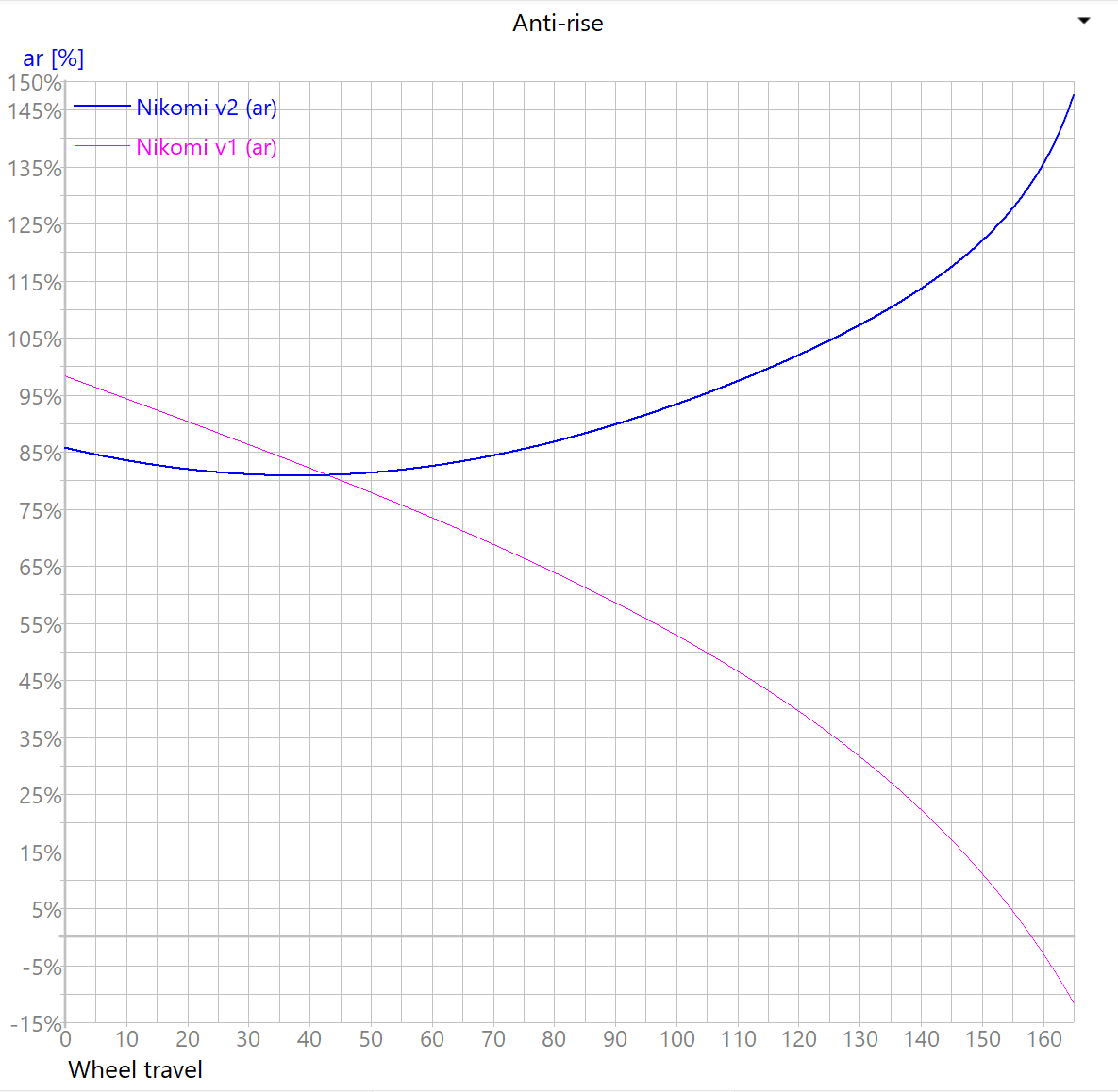
Anti-rise: Maybe my lack of riding skills, or the lack of mountains in Finland, but I haven’t noticed the effect of Anti-rise that much on any of my bikes. From what I now understand, it is better to have it high (~100%) if you are pro AND ride steep DH-trails. Then you are not pitched forwards during heavy and brief braking. For mellower trails, and riders who drag the rear brake, it is better to have lower Anti-rise (~50…80%), for better bump absorption during braking, because the rear suspension is riding higher, therefore the spring rate is lower. Again, this is not the most important factor for me, and if you think that the curve goes way up deeper in the travel, keep in mind that the force generated by Anti-rise is also dependant on the actual braking force. So, you would have to bottom-out AND brake hard at the same time, which in my view calls for trouble with any anti-rise curve. Of course, a flatter curve would be nicer. I think the jury is still out whether the curve should be rising, falling or flat.
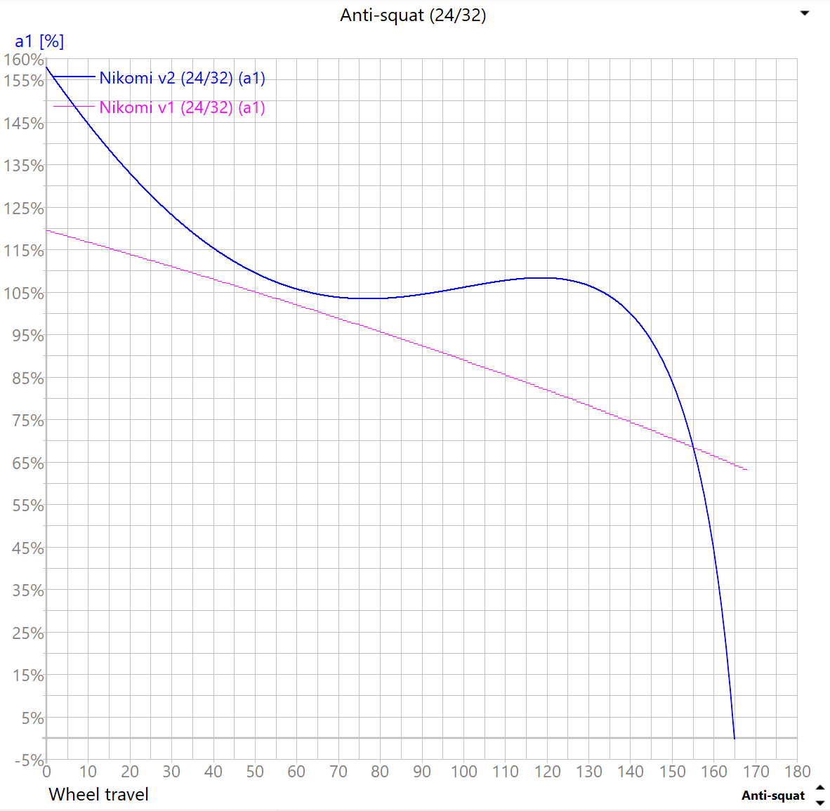
Anti-squat: On the v1, Anti-squat seemed high enough, with very little bobbing. On the v2, I don’t feel that much difference, I have learned to “rotate” the cranks more (with some ankle movement), rather than stomping with big muscles alone. I think the optimal Anti-squat is somewhere 100…120% in sag area, with a falling rate, because the spring is going to do half the job anyway deeper in the travel. So the falling rate helps to keep pedal-kickback lower deeper in the stroke. What I did notice on v2, that I lost some of the amazing ability of the v1, when pedaling on a flat trail with lots of roots. On the v1, it just floated through, and the v2 slows down more and the rear tire bounces in the air more easily.
For v3: Again, dial back closer to v1.

Forces: What I like to do in Linkage when comparing different designs and iterations, is to have the model setup with coil-spring and match the spring rates, so the sag is the same (49,5mm for 165mm @30% sag). So here we can see that v2 has much easier rate in between the top-out and sag, and the mid-support is quite massive, with an even more progressive bottom-out for that bottomless feel. The actual outcome I already told in the Leverage ratio pic… 
After all, the v2 is not that funky that it may seem from the pictures. It’s still prefectly capable and predictable, which tells me that you would have to be way off in the kinematics for a bike to be unrideable. Of course, the industry has solved these pretty much in the past 20 years or so, so for a guy like me, it is easy to land on some acceptable design. And the bike is still the combination of kinematics, geo, stiffness, weight and components.
Please, feel free to discuss, what do you think are the optimal kinematics? Am I way off in my theories and how I feel them on the trail?
3 Likes
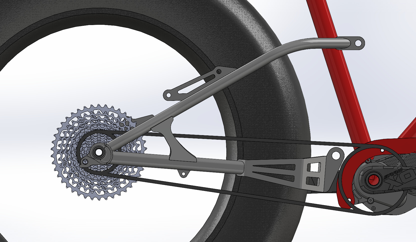
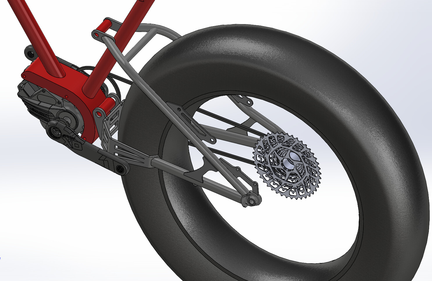
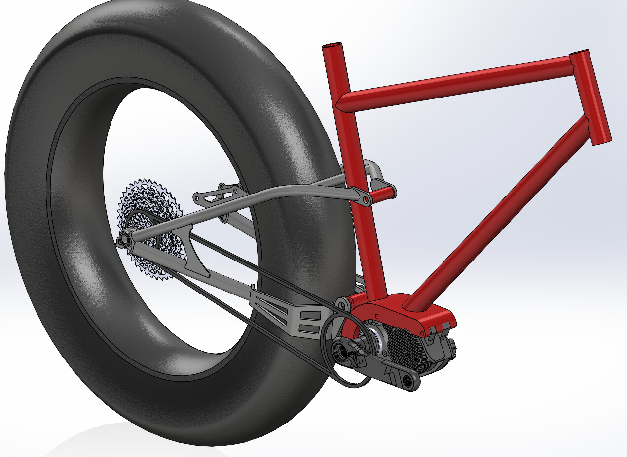
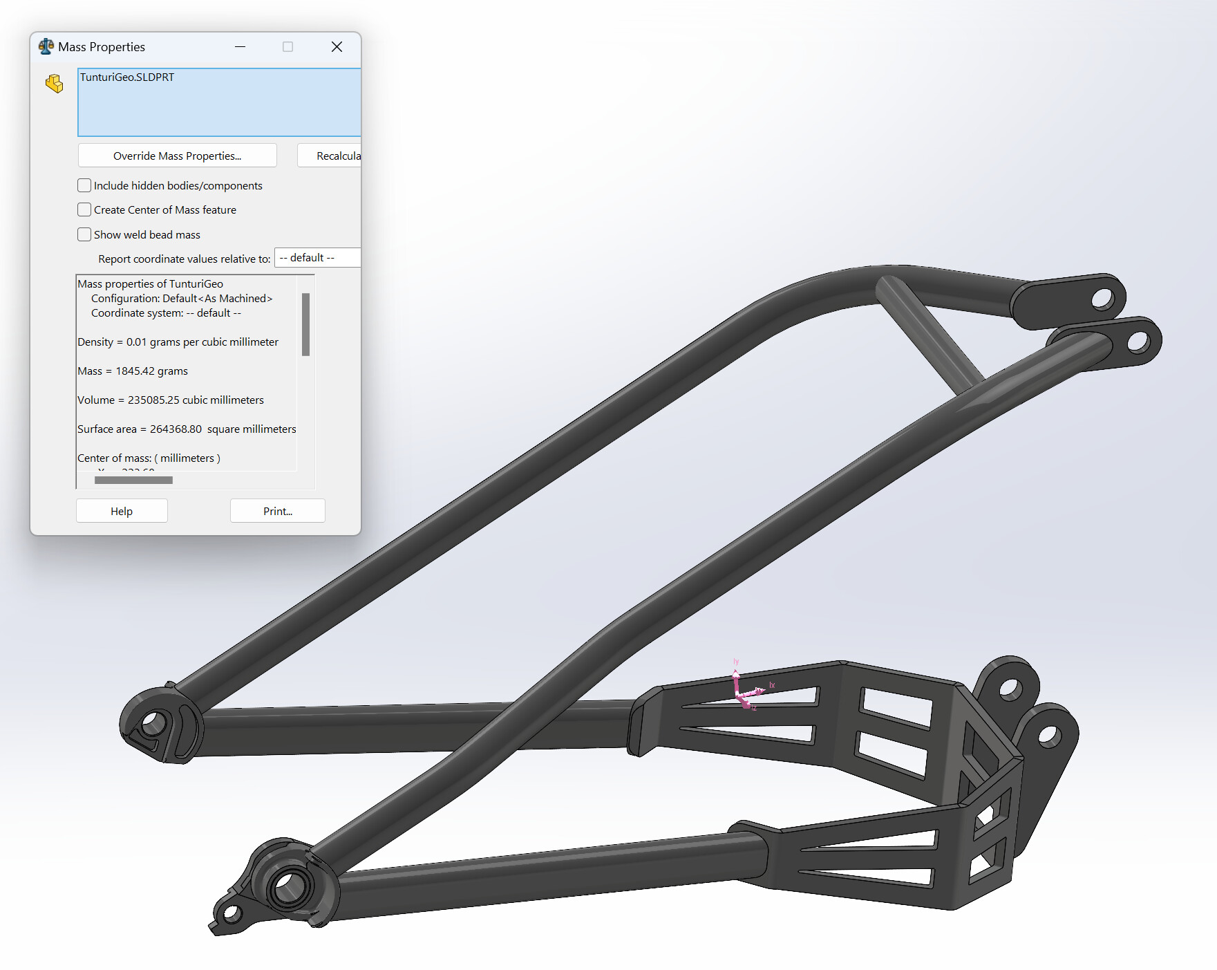
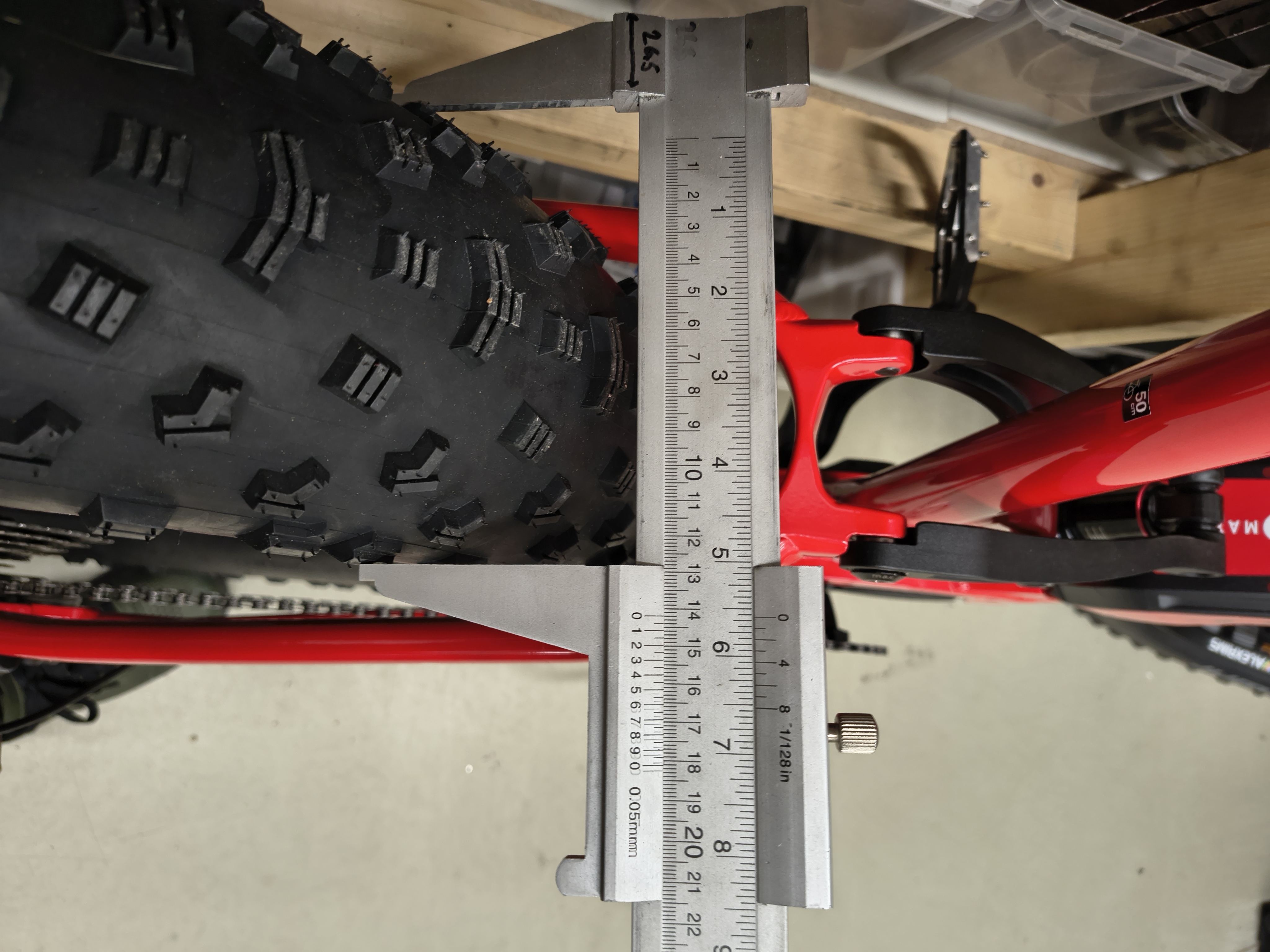
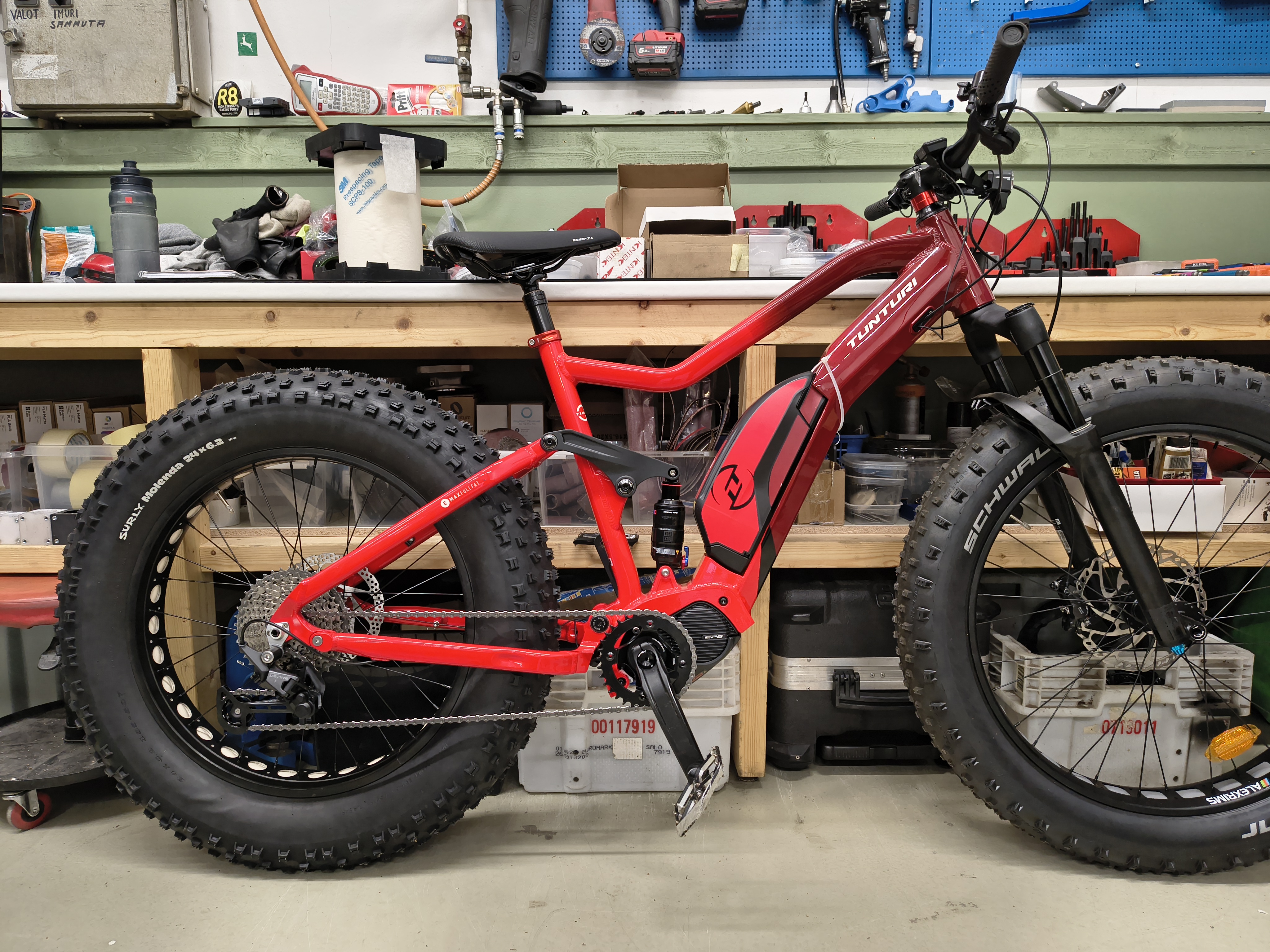
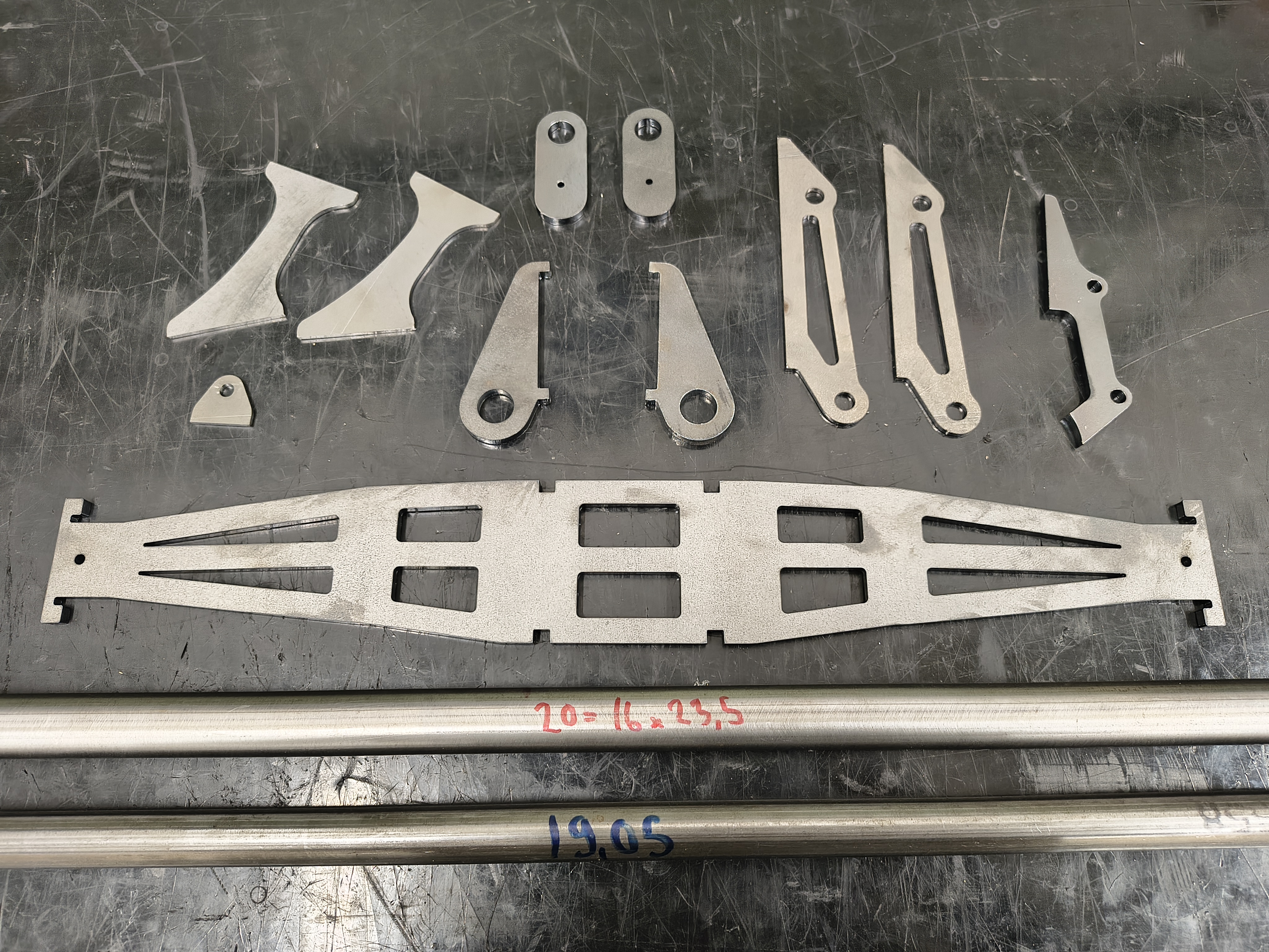
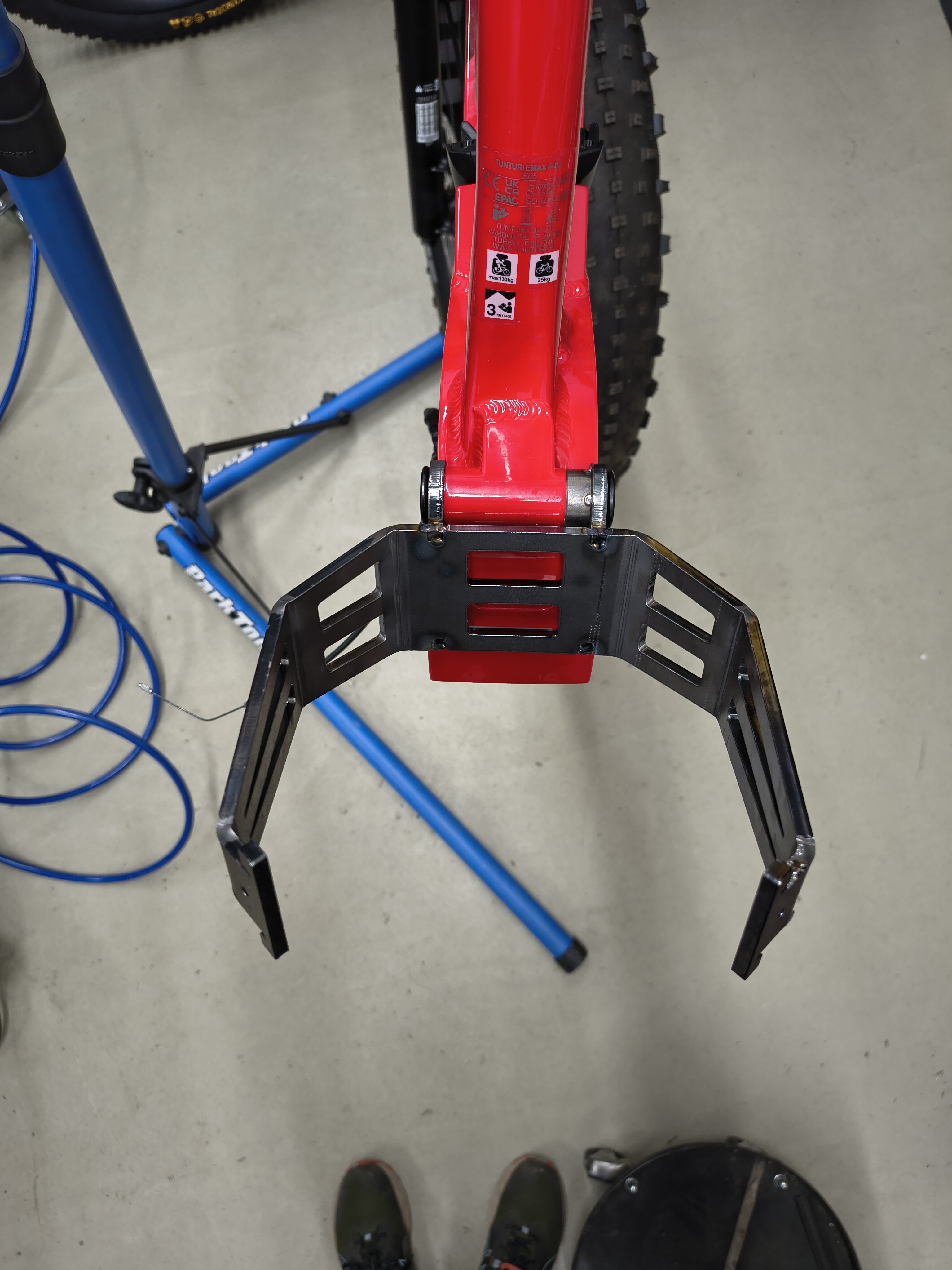
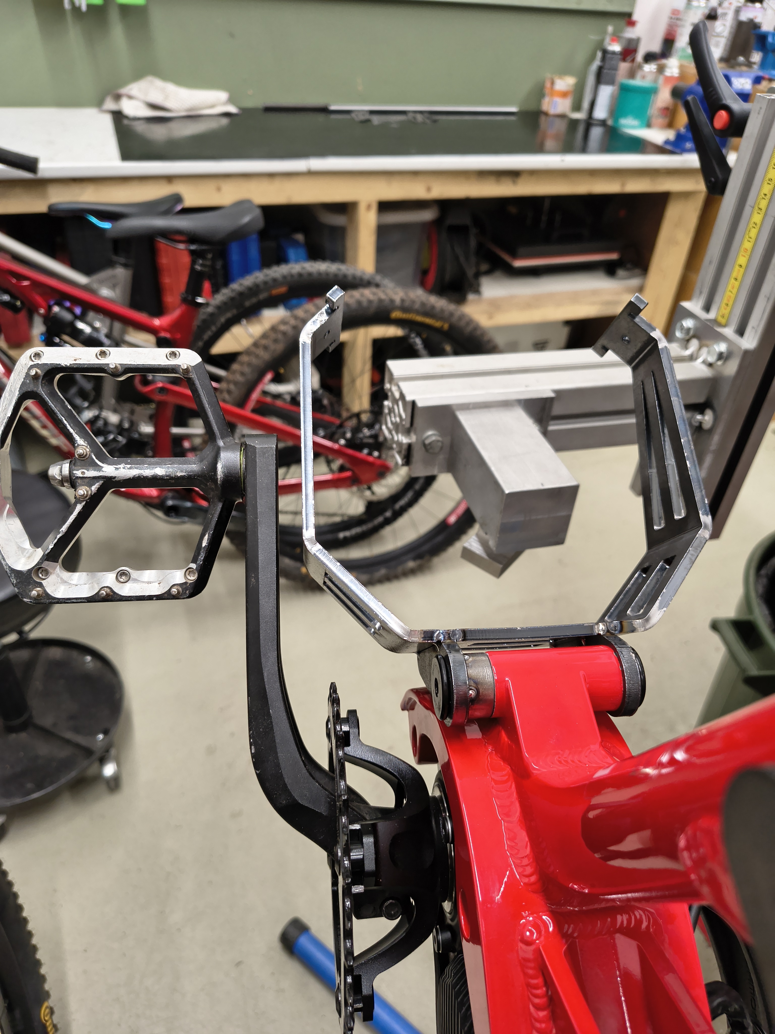
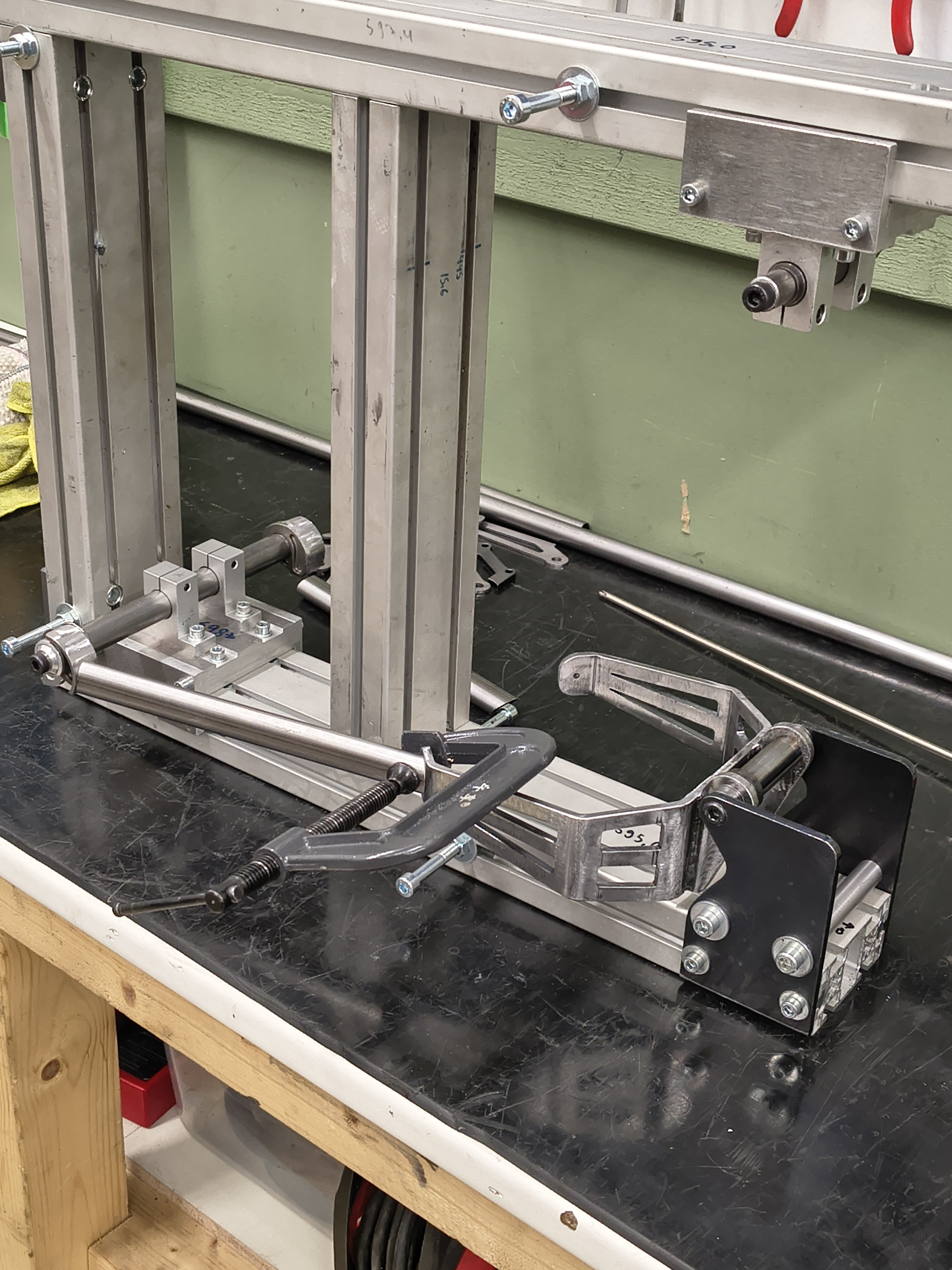
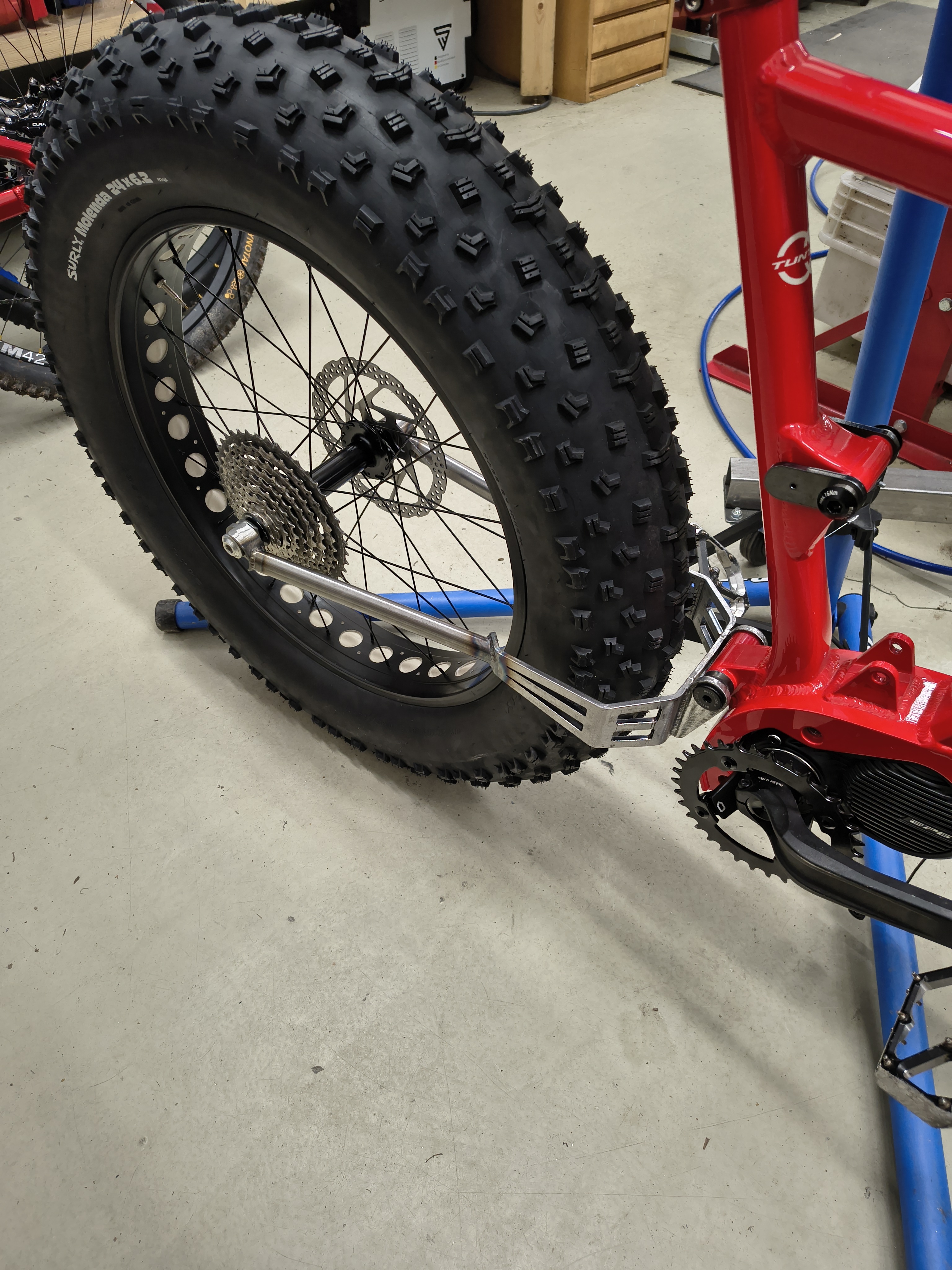
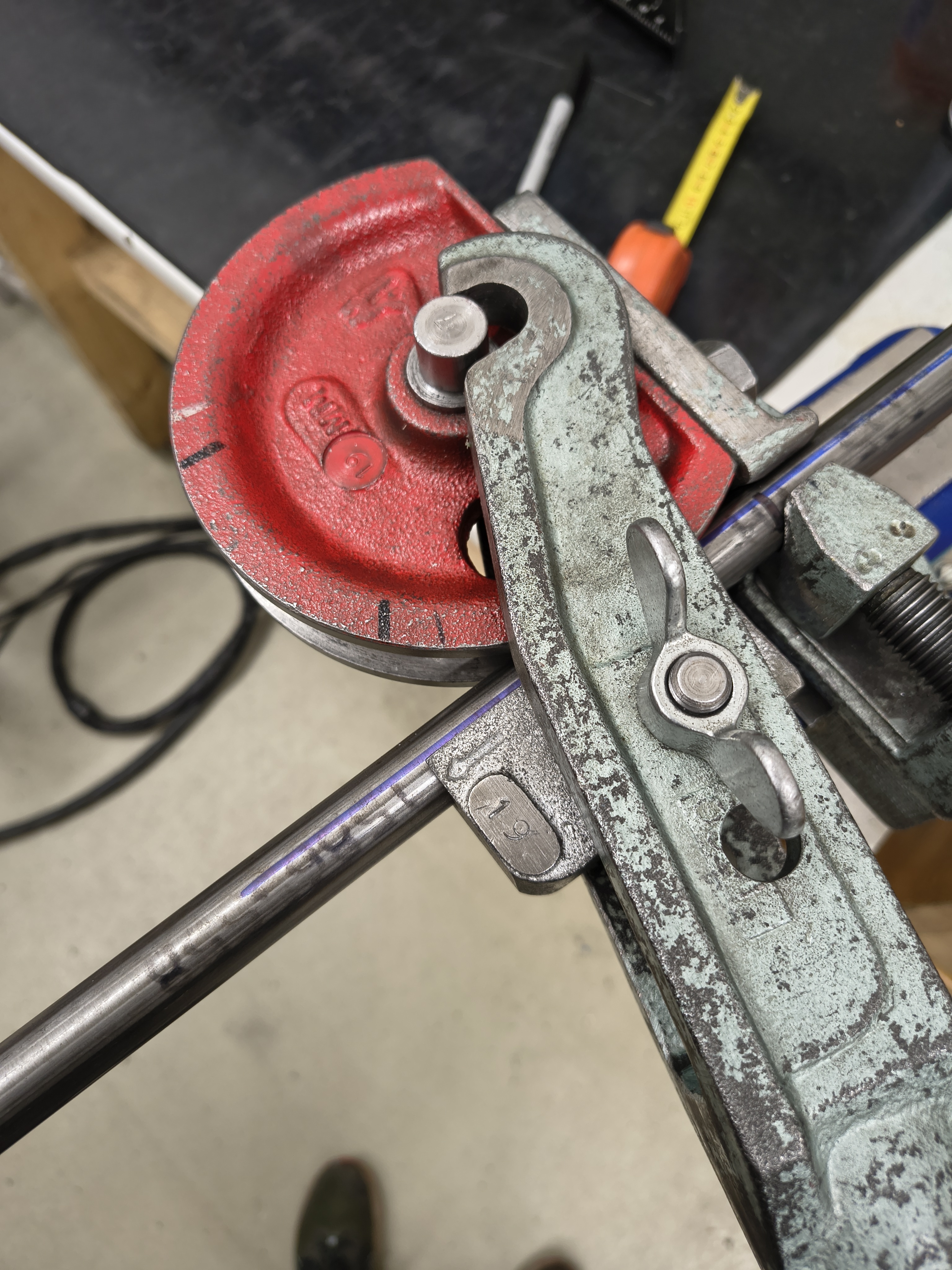
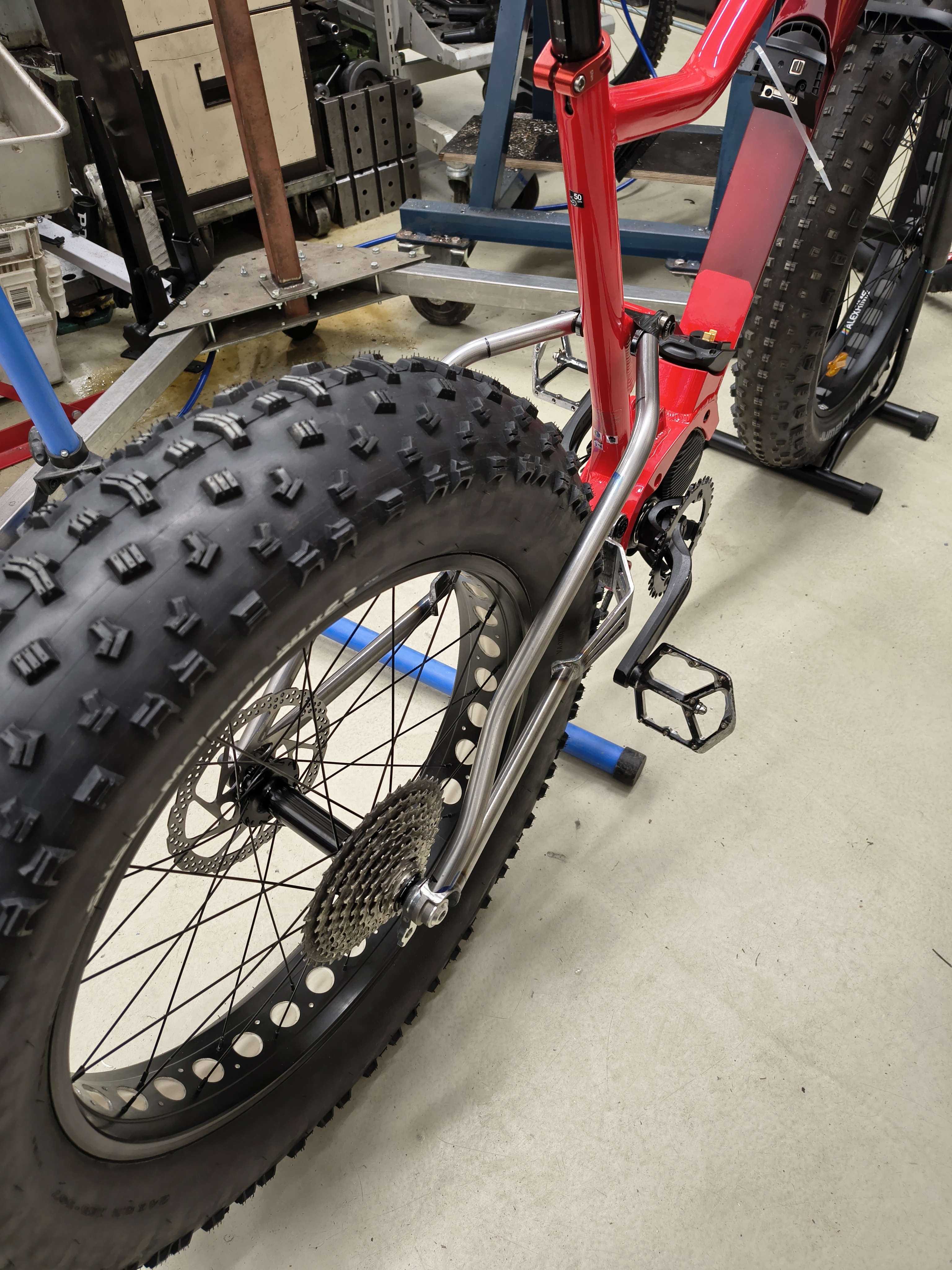
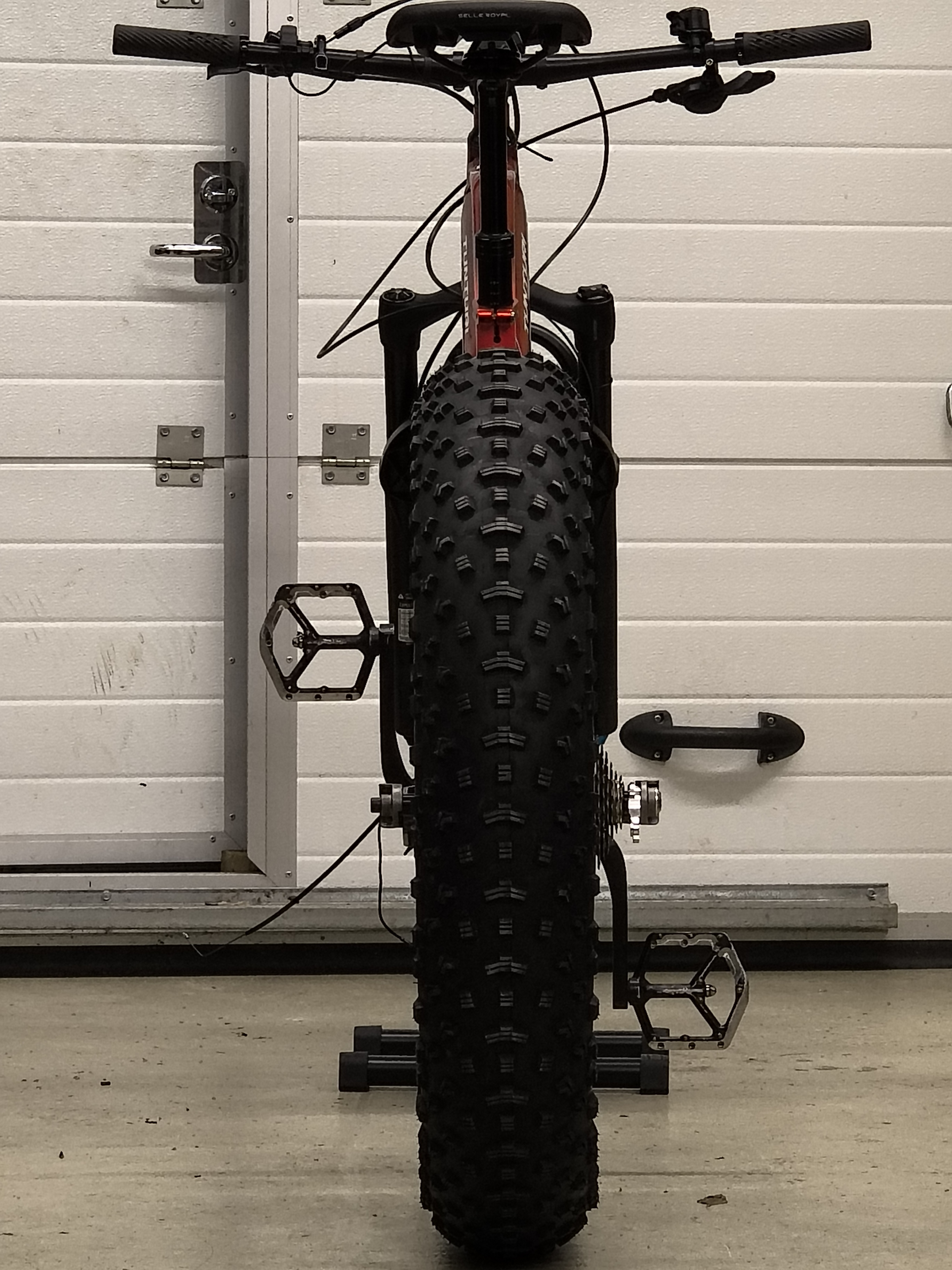
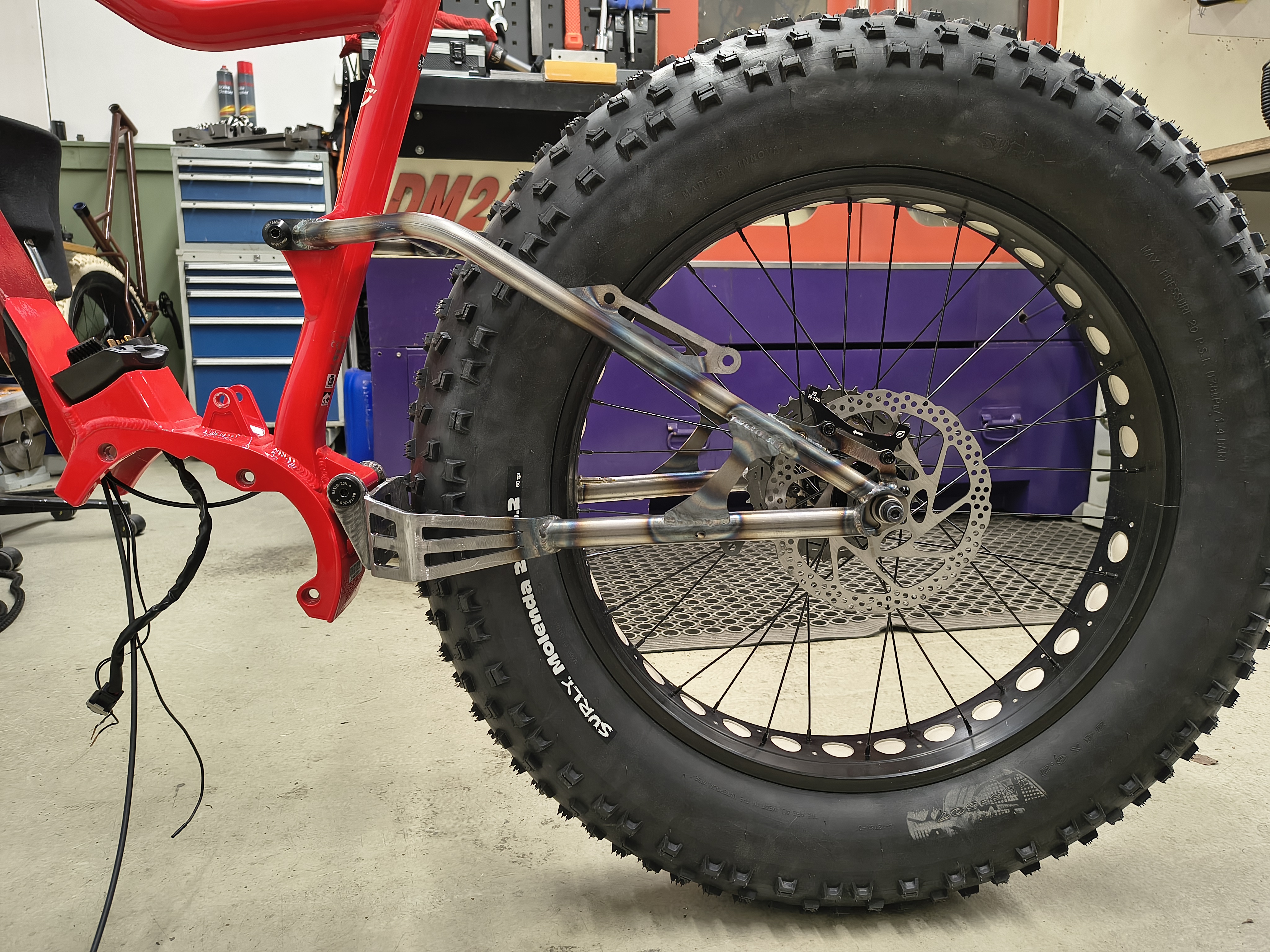
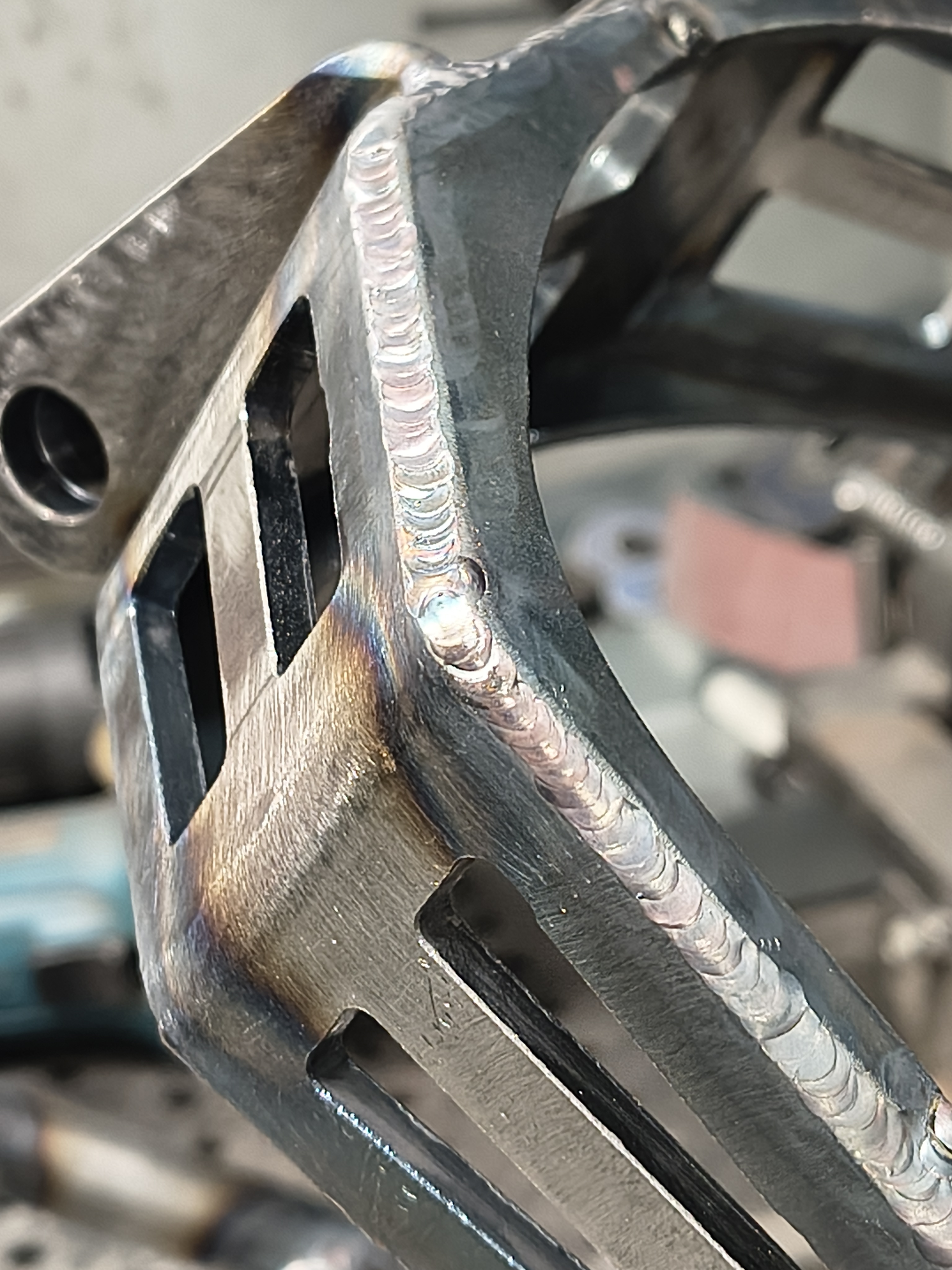
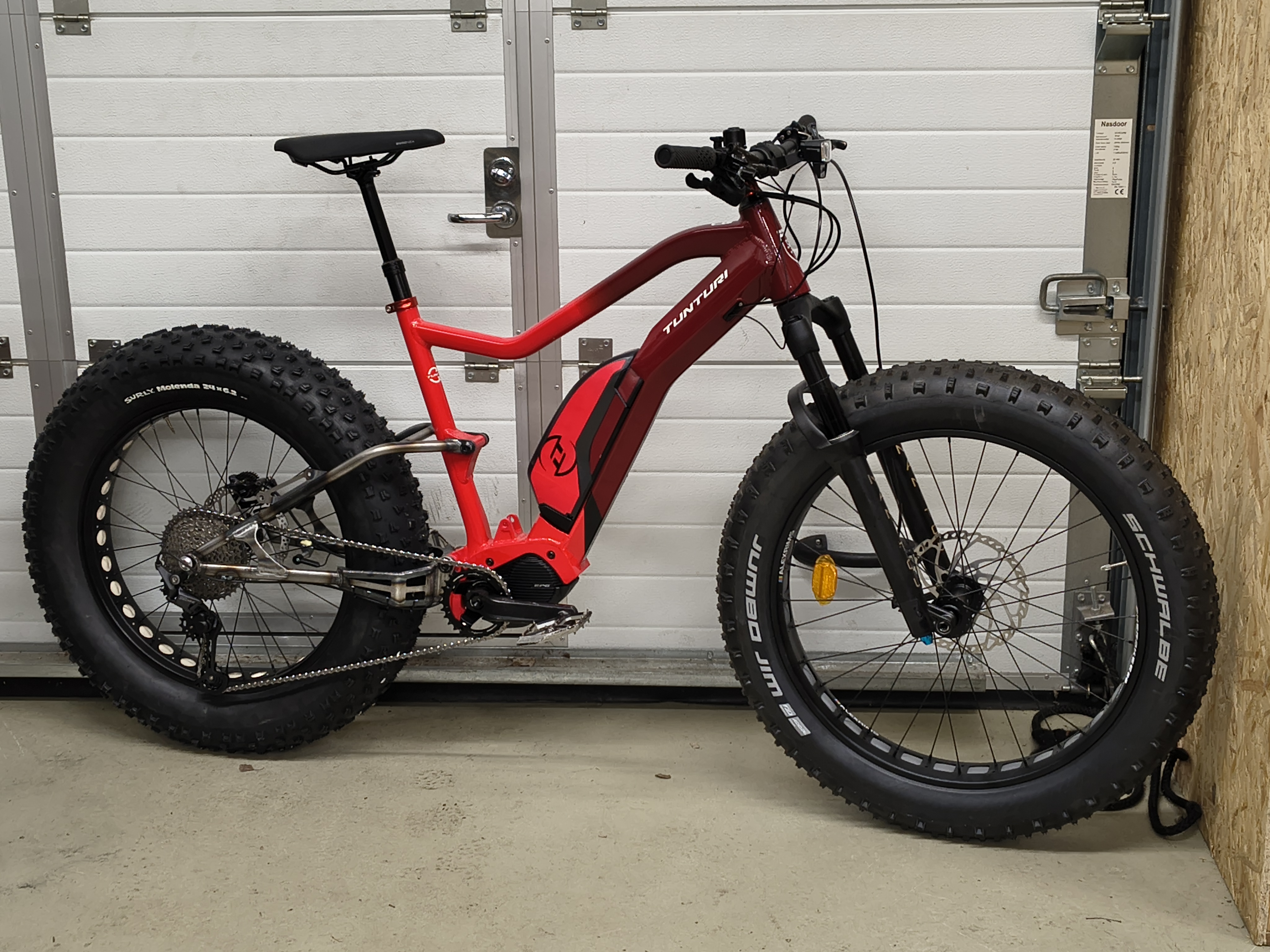
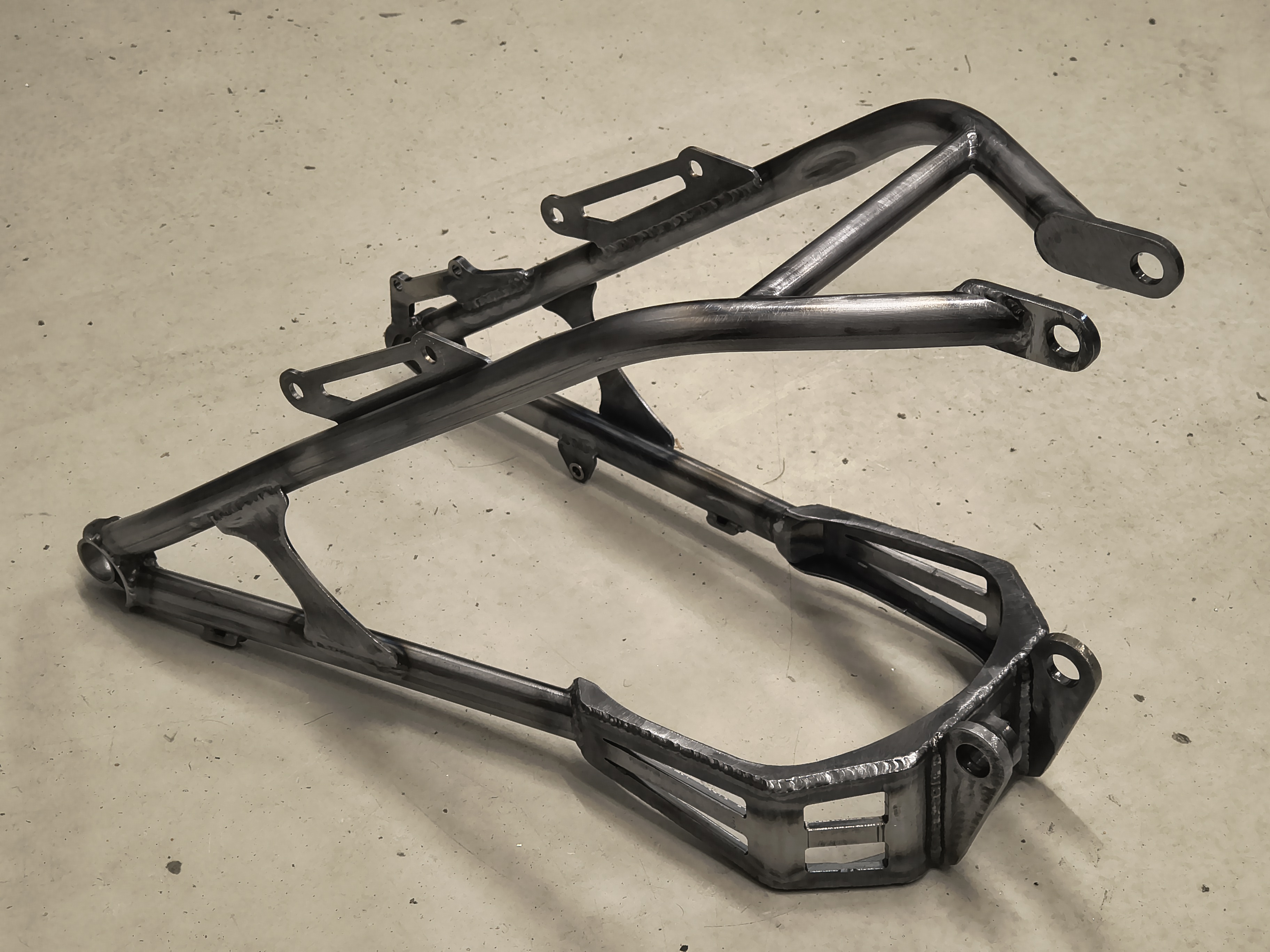
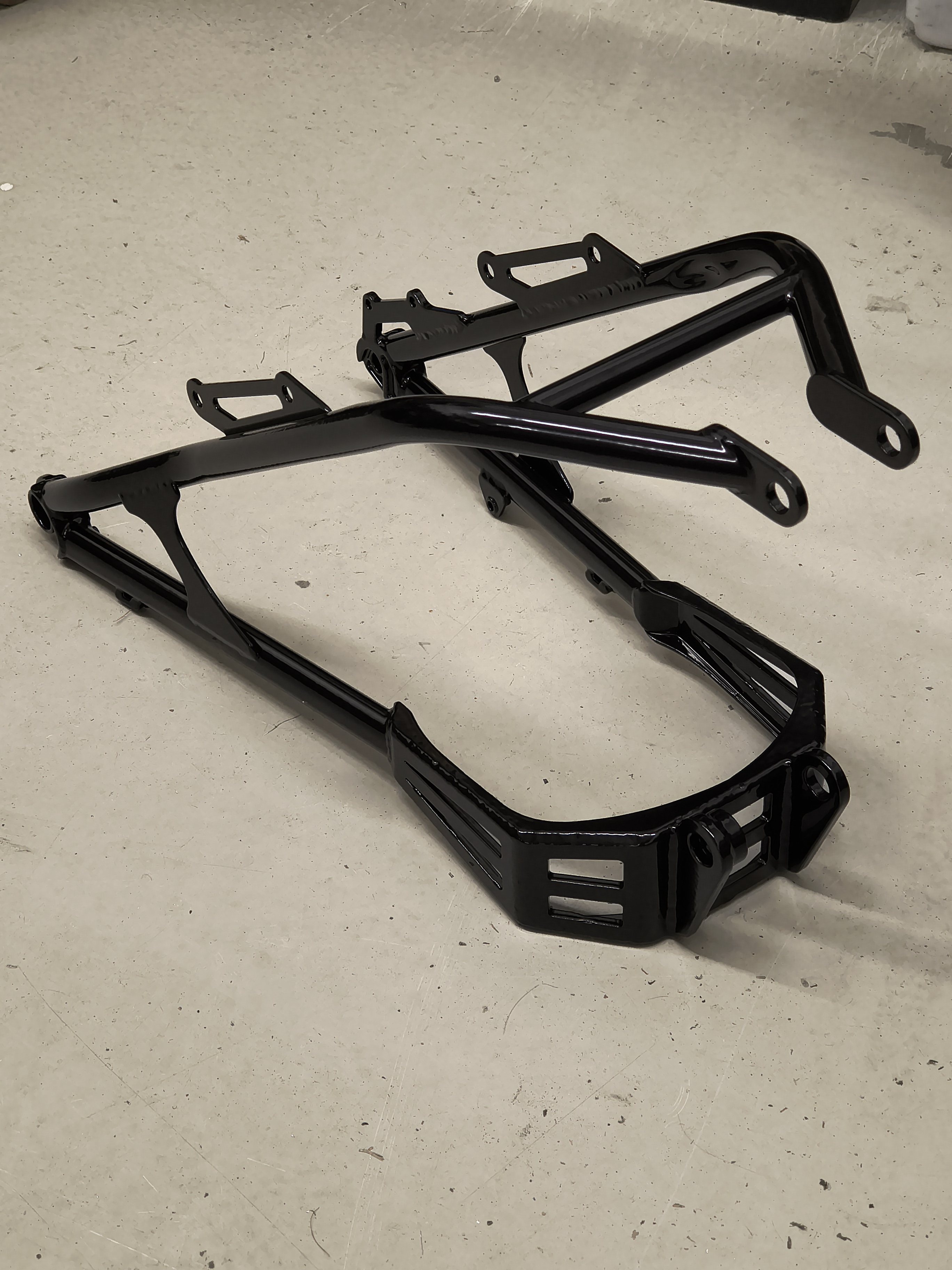
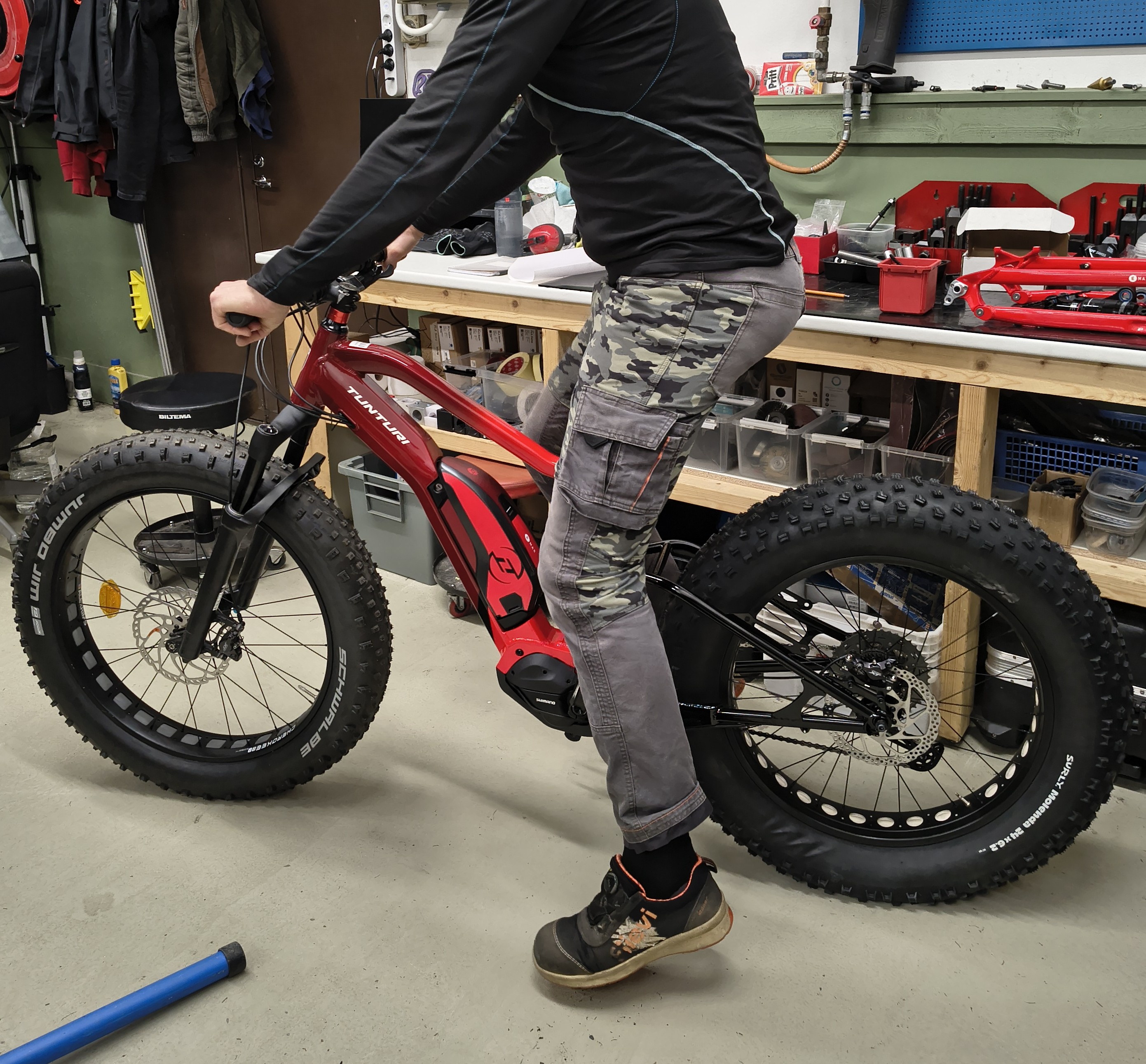
Last winter, I did my first paying gig as Nikomi Bikes (don’t worry I’m not giving up my day job  ). A friend has a business in trail building, and he also does maintaining during winter. A good solution (one of many) for grooming winter trails has been pulling a car tire with a fat bike. E-fatbikes are great for this because, of course, it takes quite the effort to pull anything behind the bike, also the power output is very smooth on ebike, and also the mass does not hurt here. So to maximize the effort and capability of the bike, this friend came up with the idea of having the Surly 24 x 6.2 rear tire fitted to this Tunturi full-suspension e-fat. This way the bike itself is not modified, I would just make a hardtail conversion kit for it. The Tunturi could always be restored to original form by swapping the original parts.
As usual to me on everything I make nowadays, I designed the thing in Solidworks, to work out all the details including the chainline and offset needed for the rear hub.
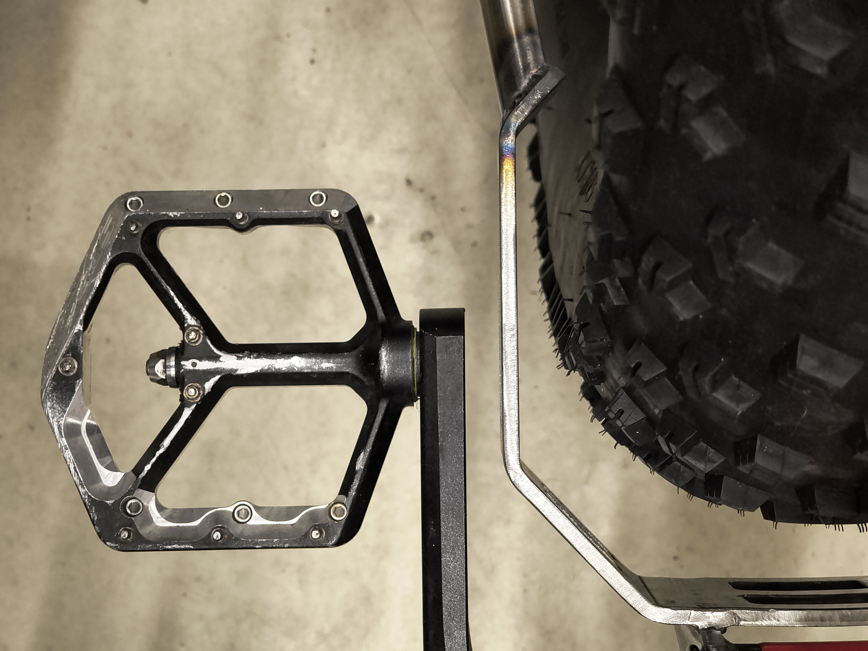
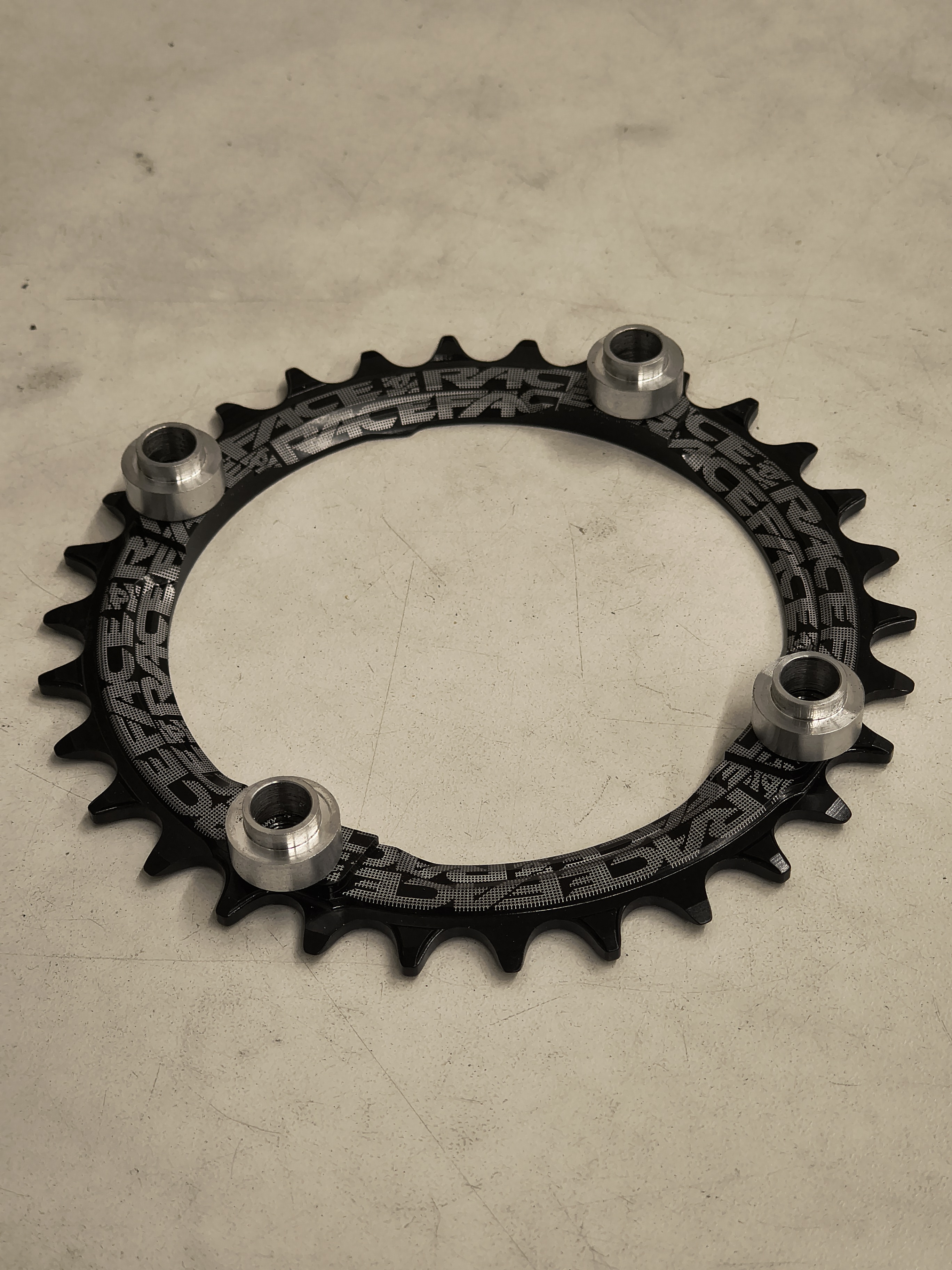
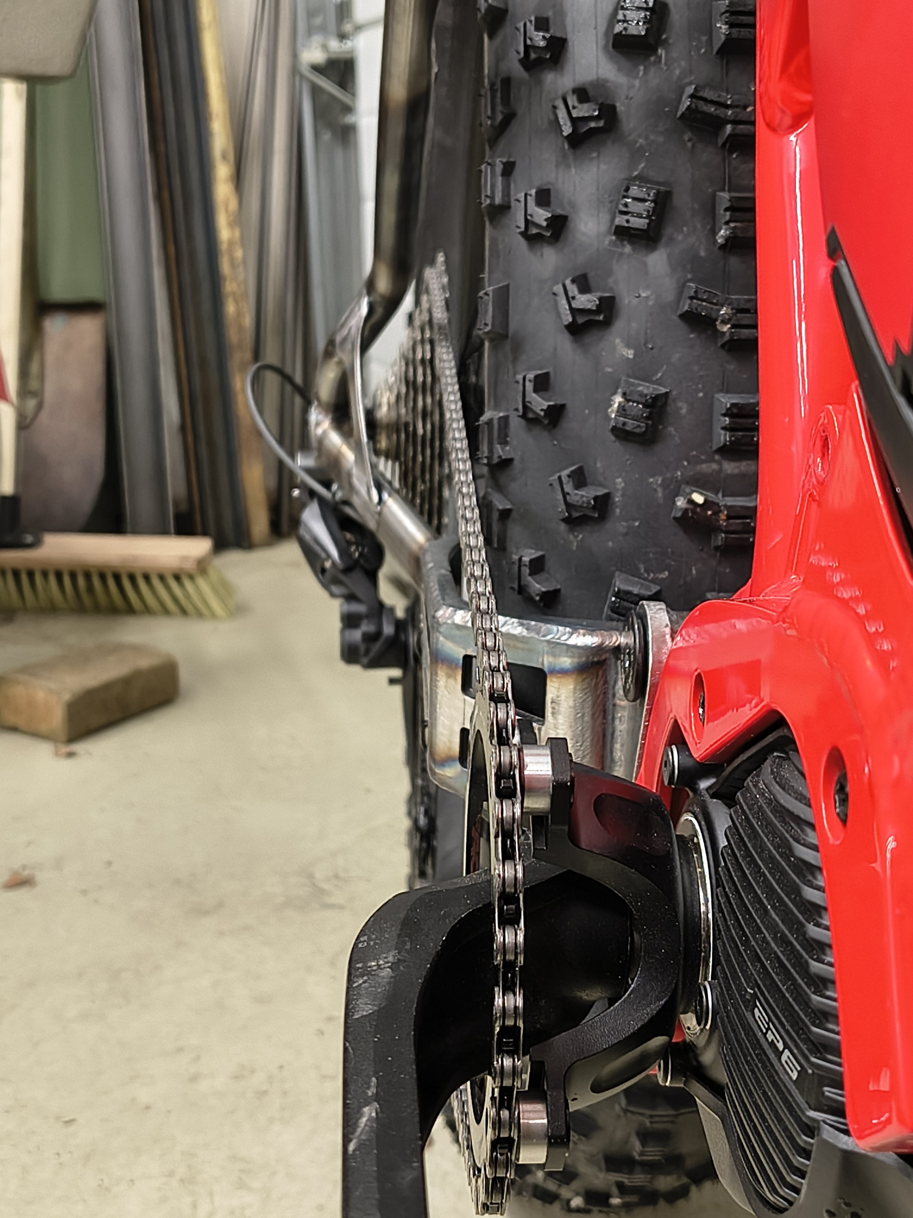
The rear hub ended having 10mm offset, on top of the UDH dropout. For the chainring I turned some spacers to widen the chainline 8mm.
Chainstay length is 495mm.
The customer worked out the cassette, which he reduced to 9-speed (you don’t need that many on ebike do you?). On the test ride I did, there was some chainrub on the smallest gear though.
It came out a bit flexy still, but it works!
Are there other bikes in the world with this tire and a “normal” drivetrain? How about ebike?
I don’t know.
Enjoy!



3 Likes
This is so rad! Nice work
1 Like
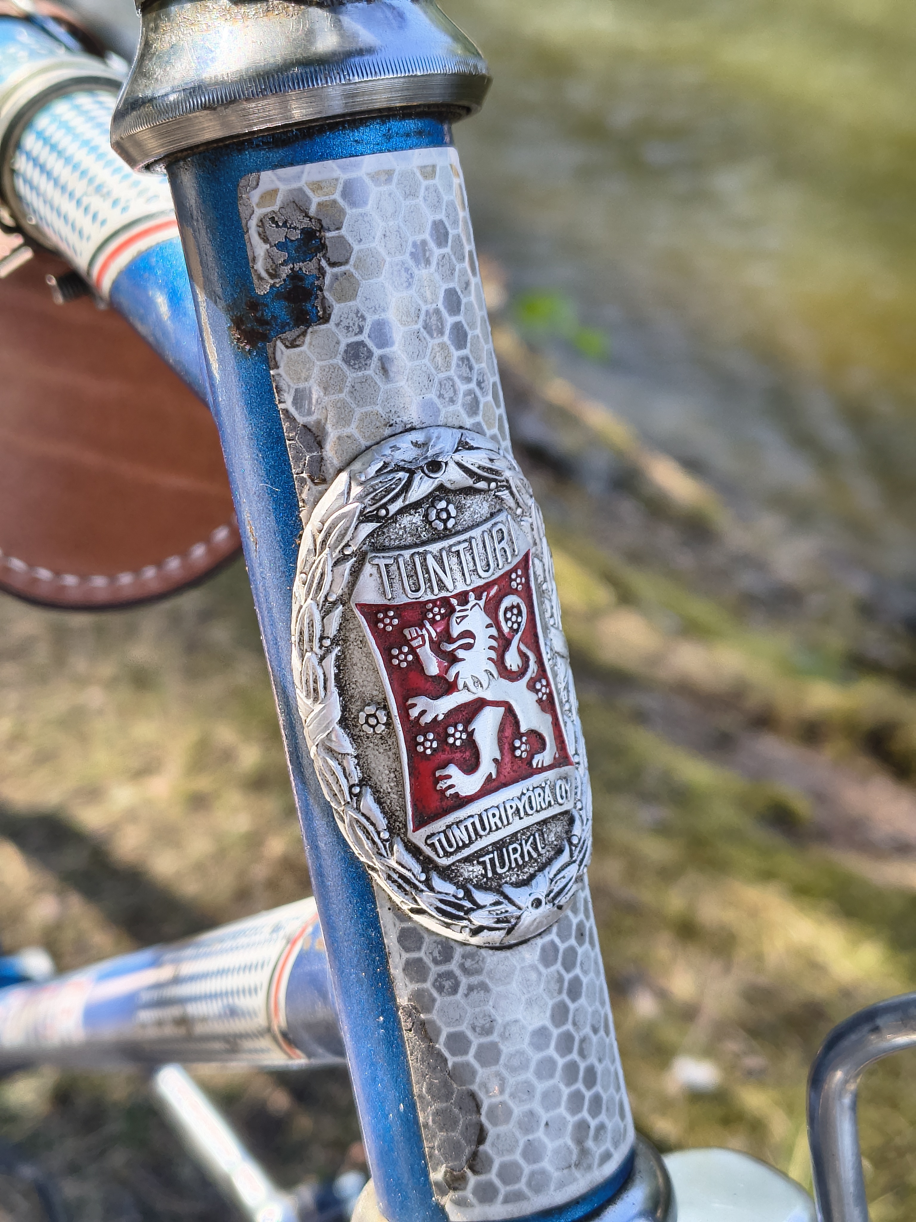
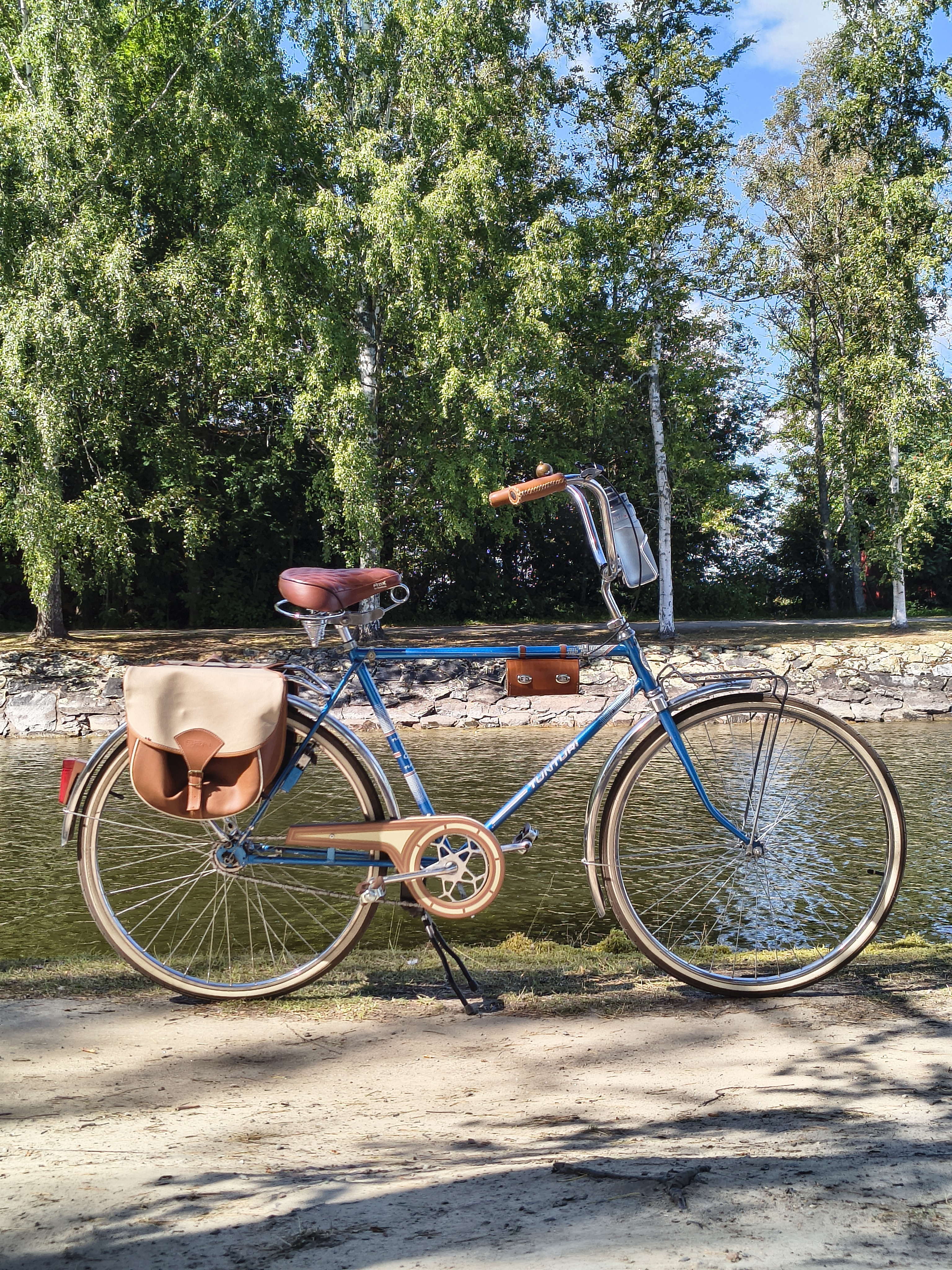
Funnily, this awesomeness is also a Tunturi, same Finnish brand as the fatbike above. I guess it’s straight gauge, at least it is MIG-welded Rode it 68km last sunday, my ass is still sore  The angles are pretty wild, notice the “raised and reversed” cockpit
1 Like
Moving to an actual house has been my dream for a long time, and in November last year we were finally able to buy one (nice house came to market), after living 6 years in a 1,5 room (38 m2) apartment with my girlfriend.
Being able to do stuff in my own garage is just so cool. And actually storing my bikes at home is a novelty I did not have before!
But before I get to do any stuff, the garage needs stuff to be done So here’s a short story of “Nikomi Bikes workshop” in 2026.
It’s ~ 3,25 m x 5 m = 16,25 m2 (~ 175 sqft). Plus the 2 m2 technical room / storage behind the door.

As bought.

I painted the floors and walls, before moving stuff in.
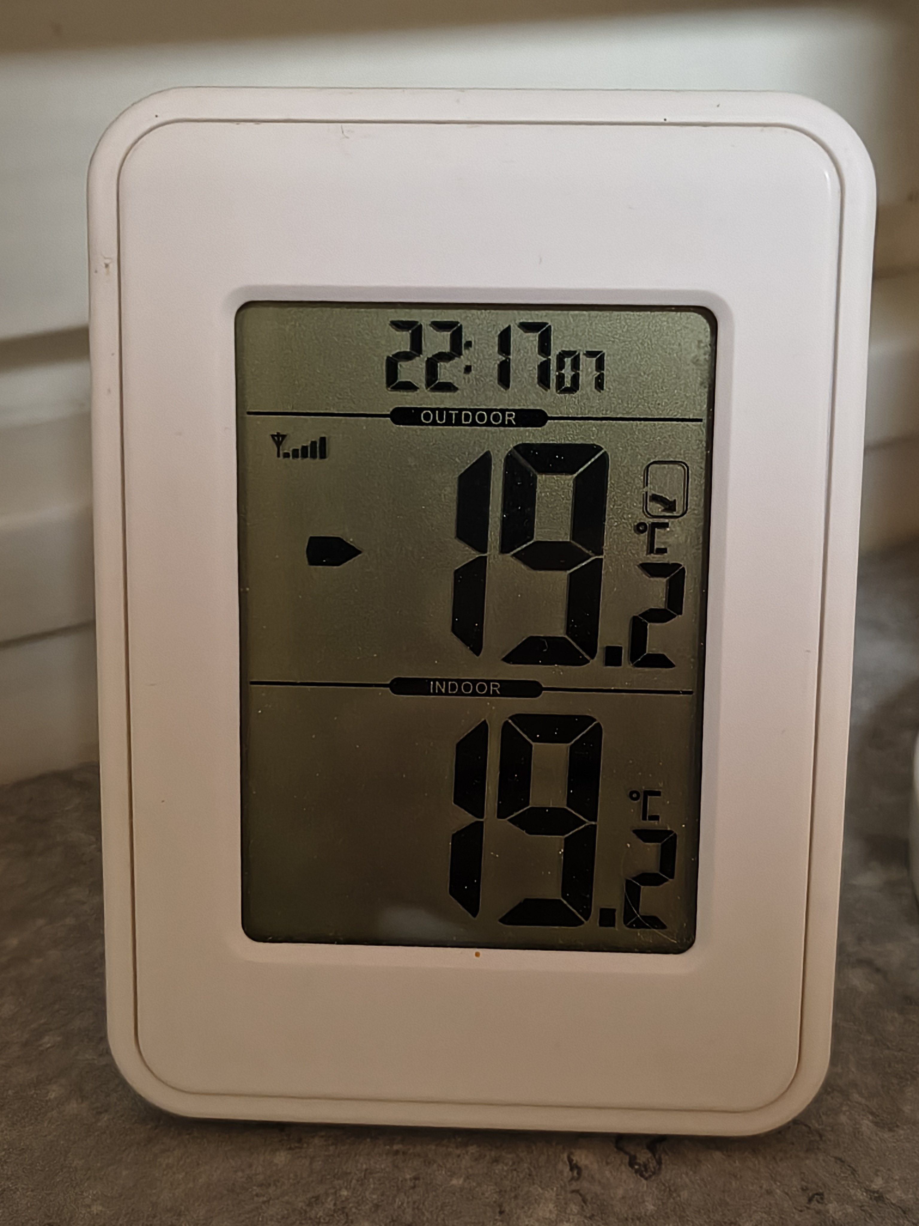
It was pretty cold winter, for painting the non-heated floor It went well though.
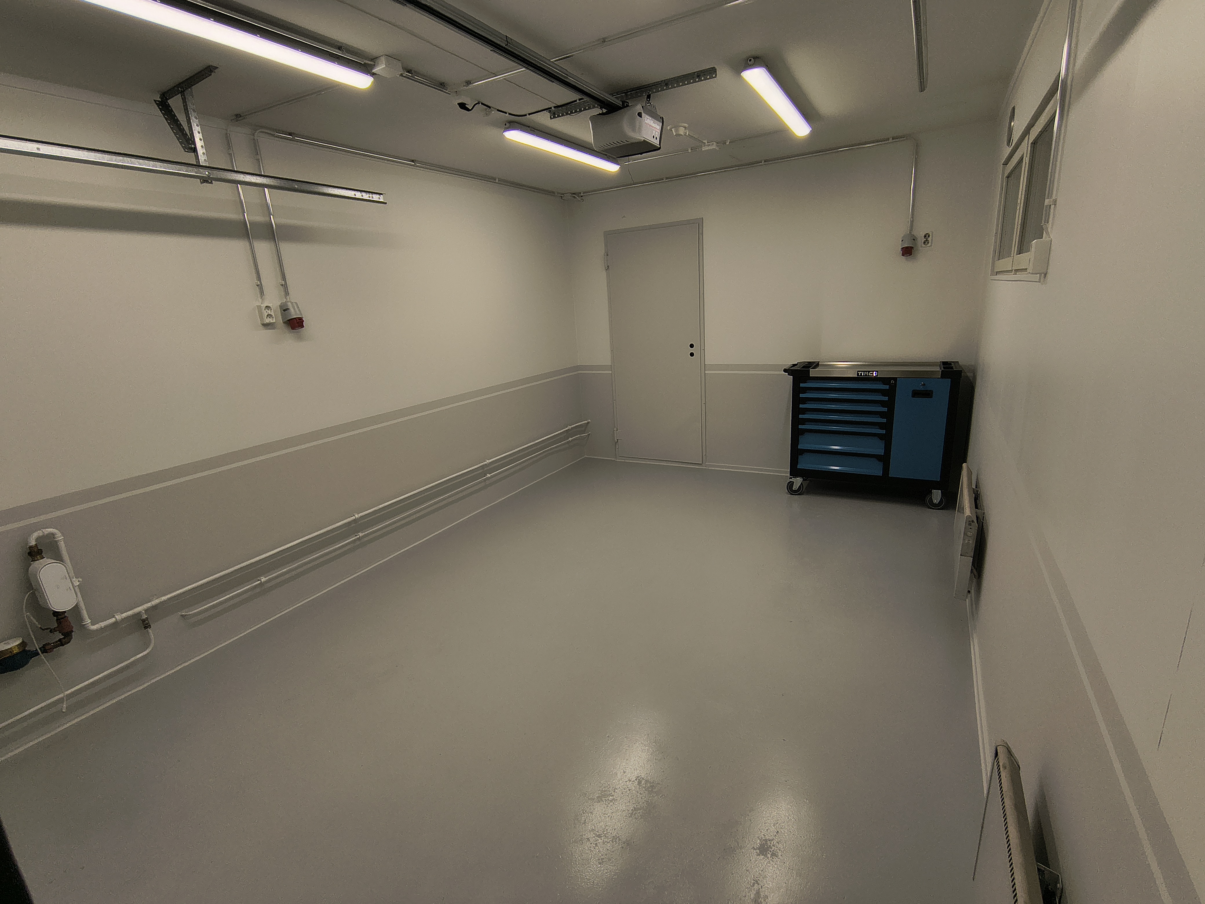
Painted. Also new LED-lighting.
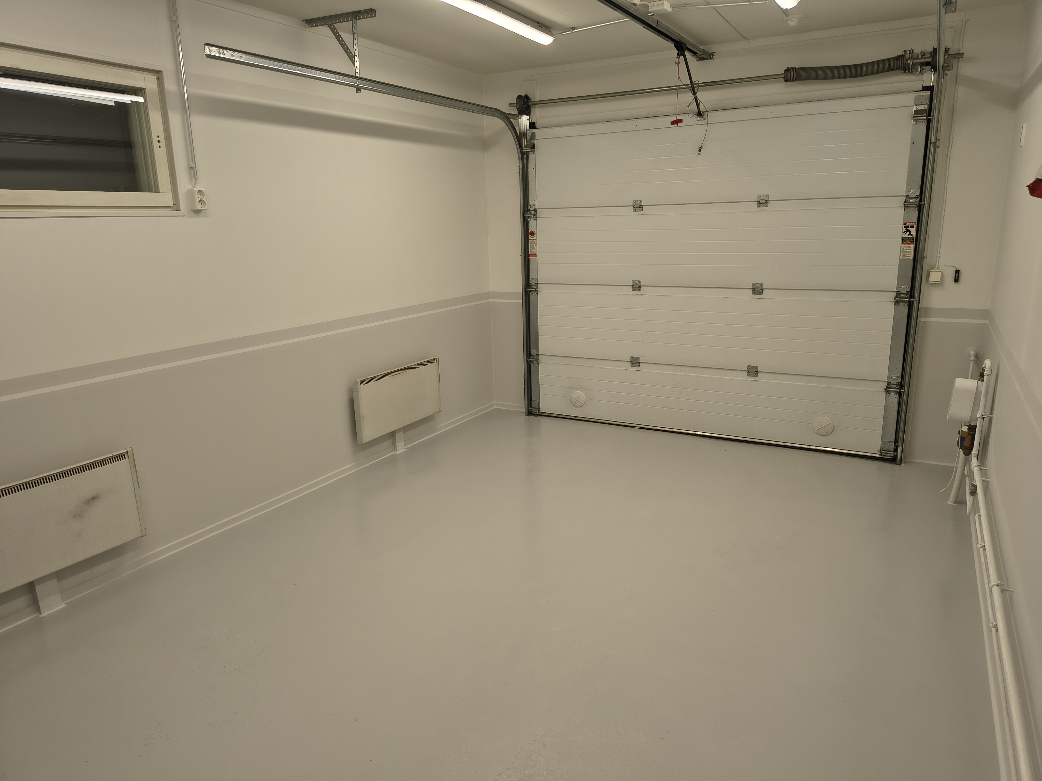
Electric door, nice.
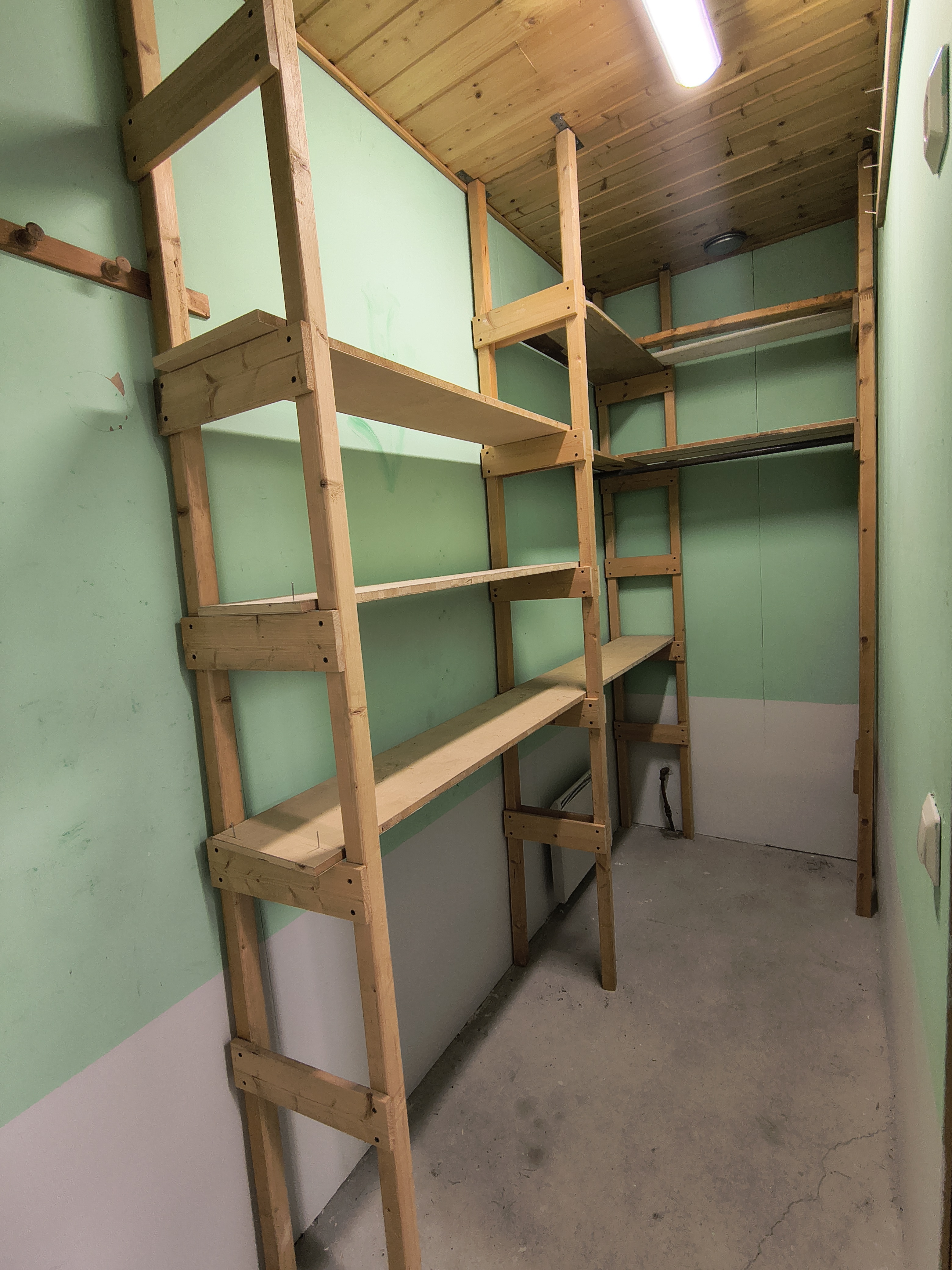
The technical room / storage as bought.
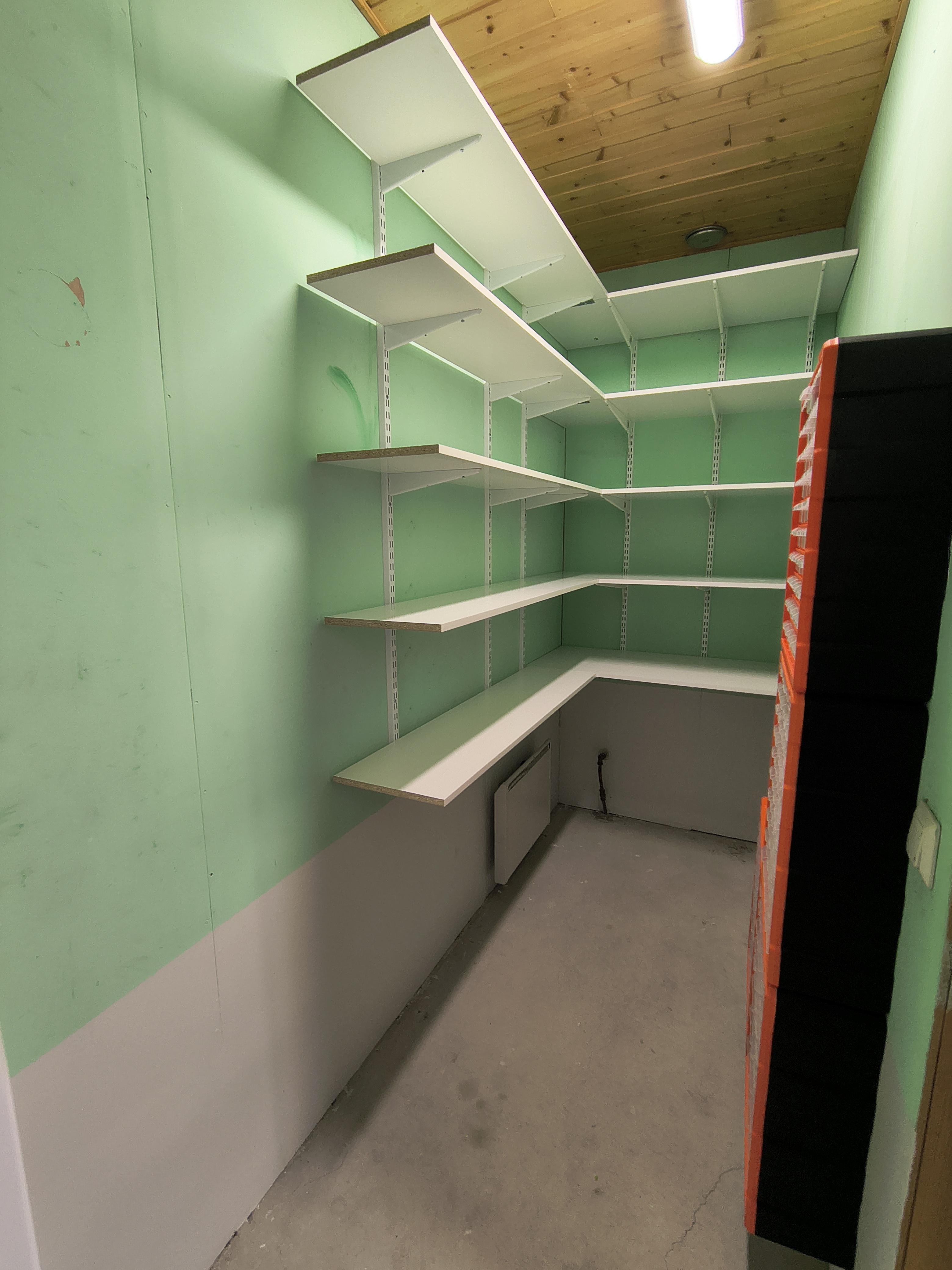
New shelves and bolt / screw organizers.
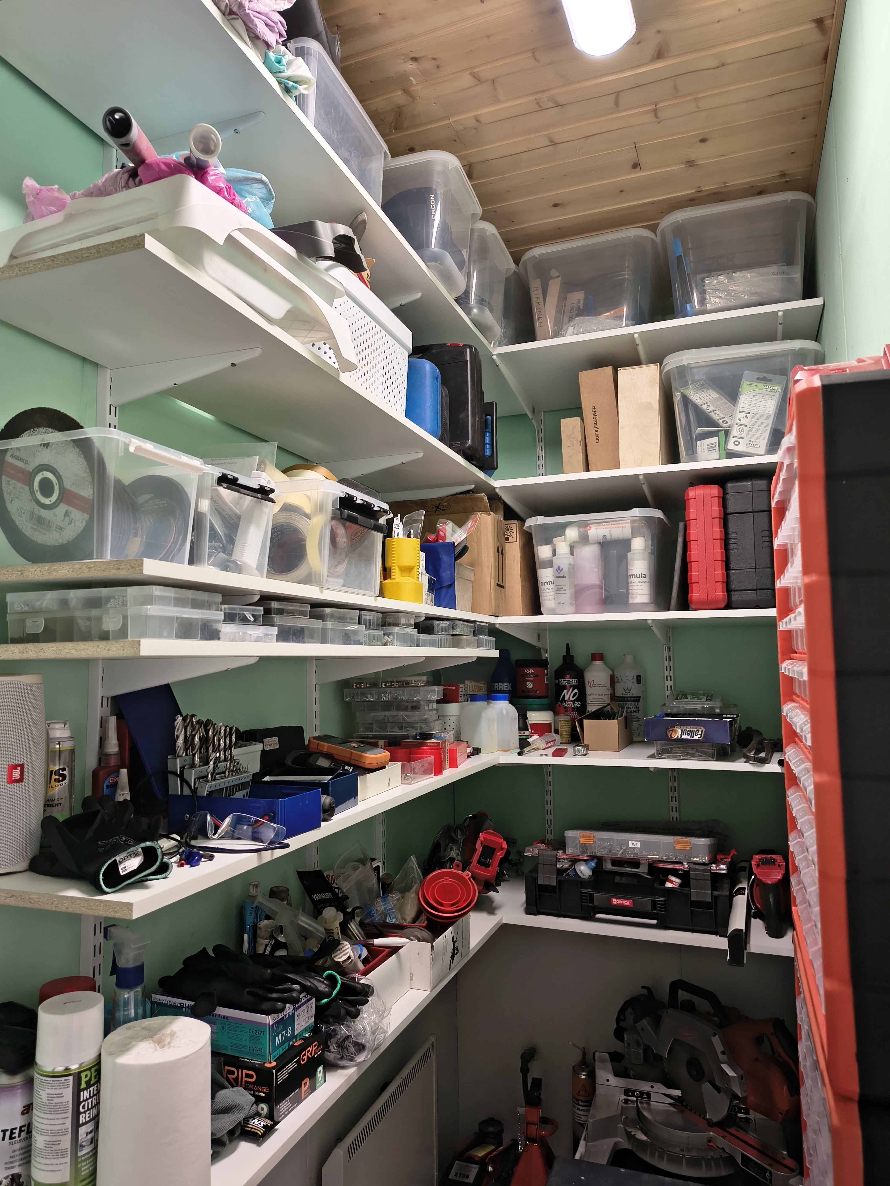
Small stuff that is not in use everyday goes here.
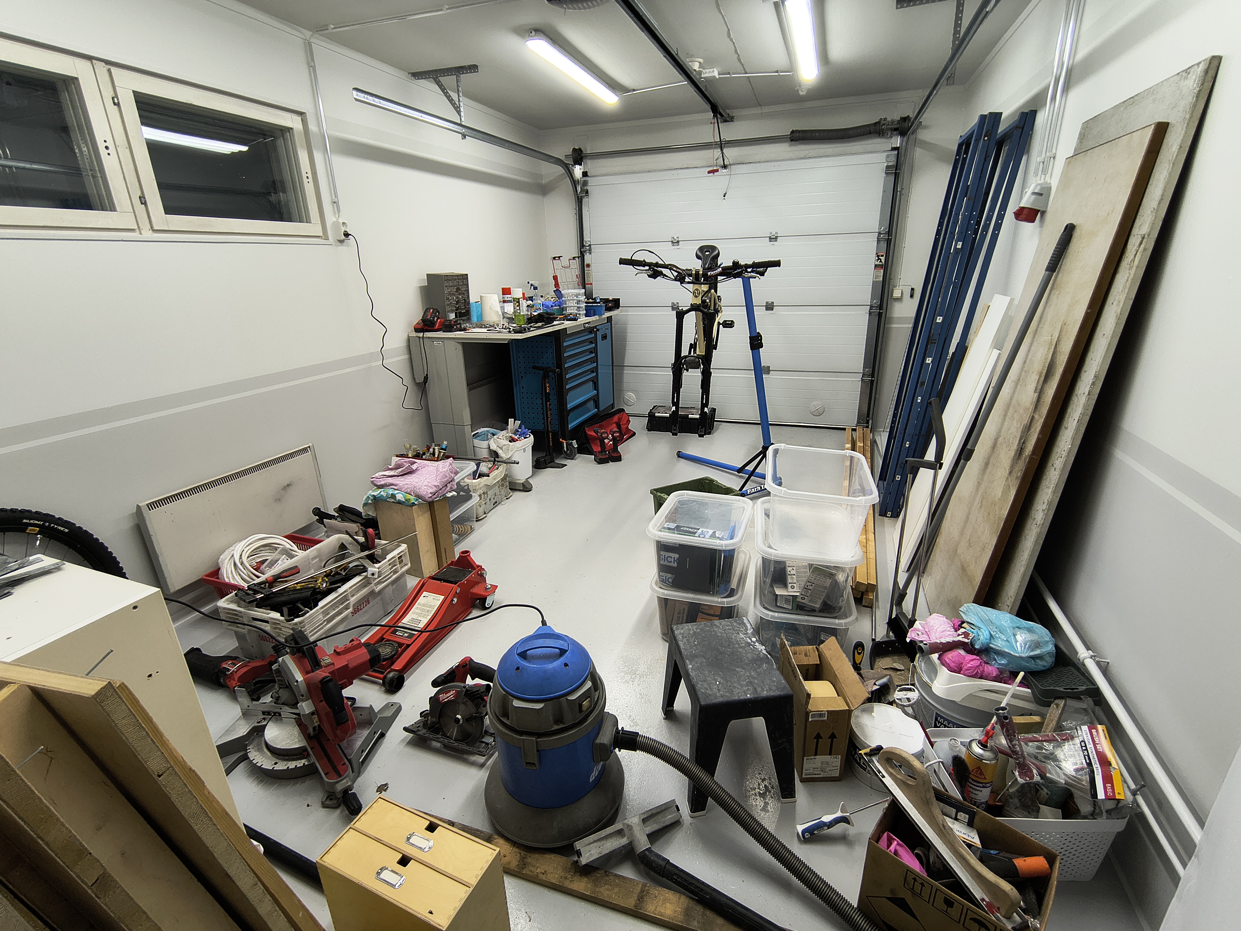
Moving stuff back and forth is a huge part of my life
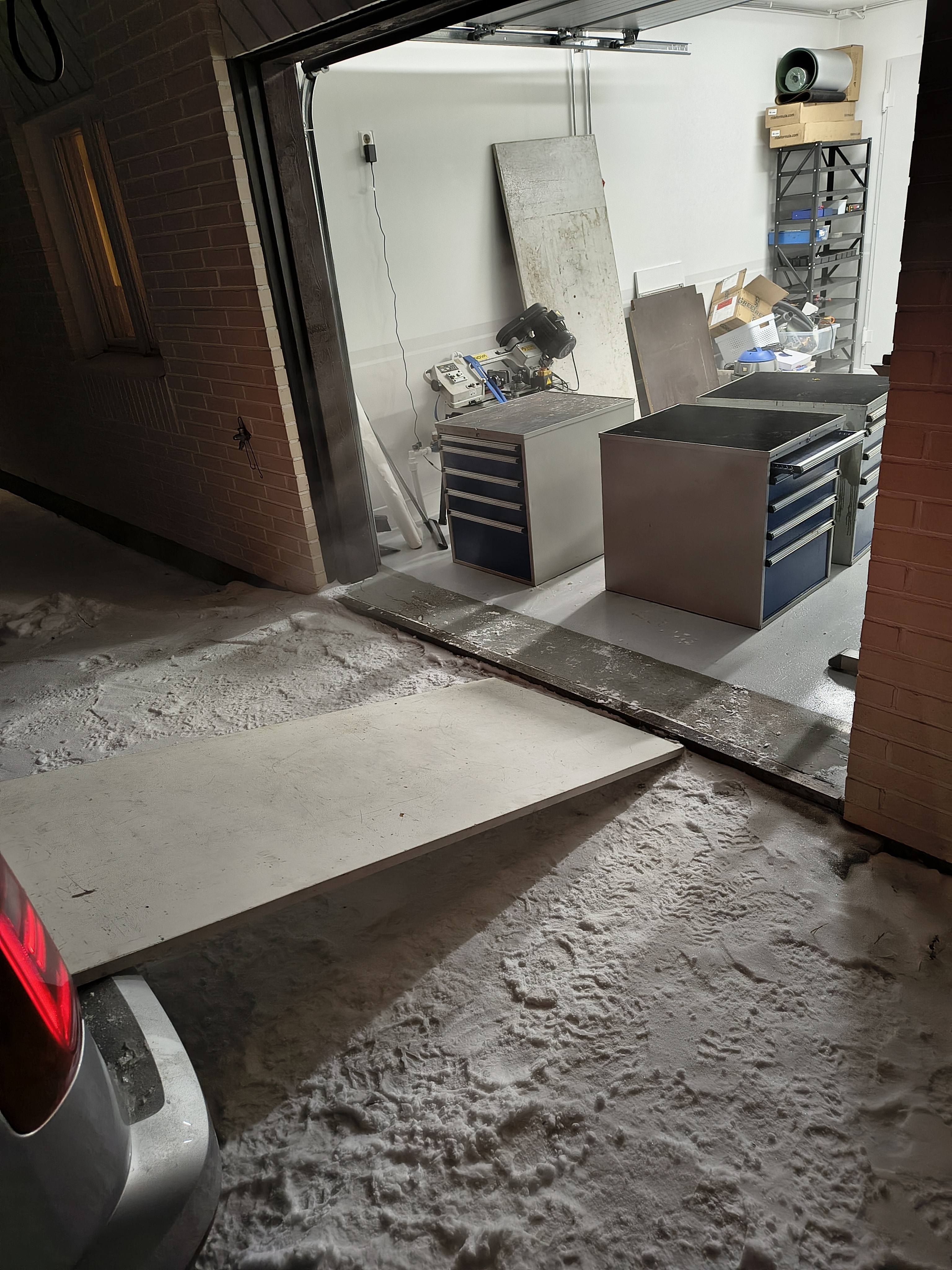
Got me some GWS / Treston drawer units. Slid right in!

Bought a lathe!
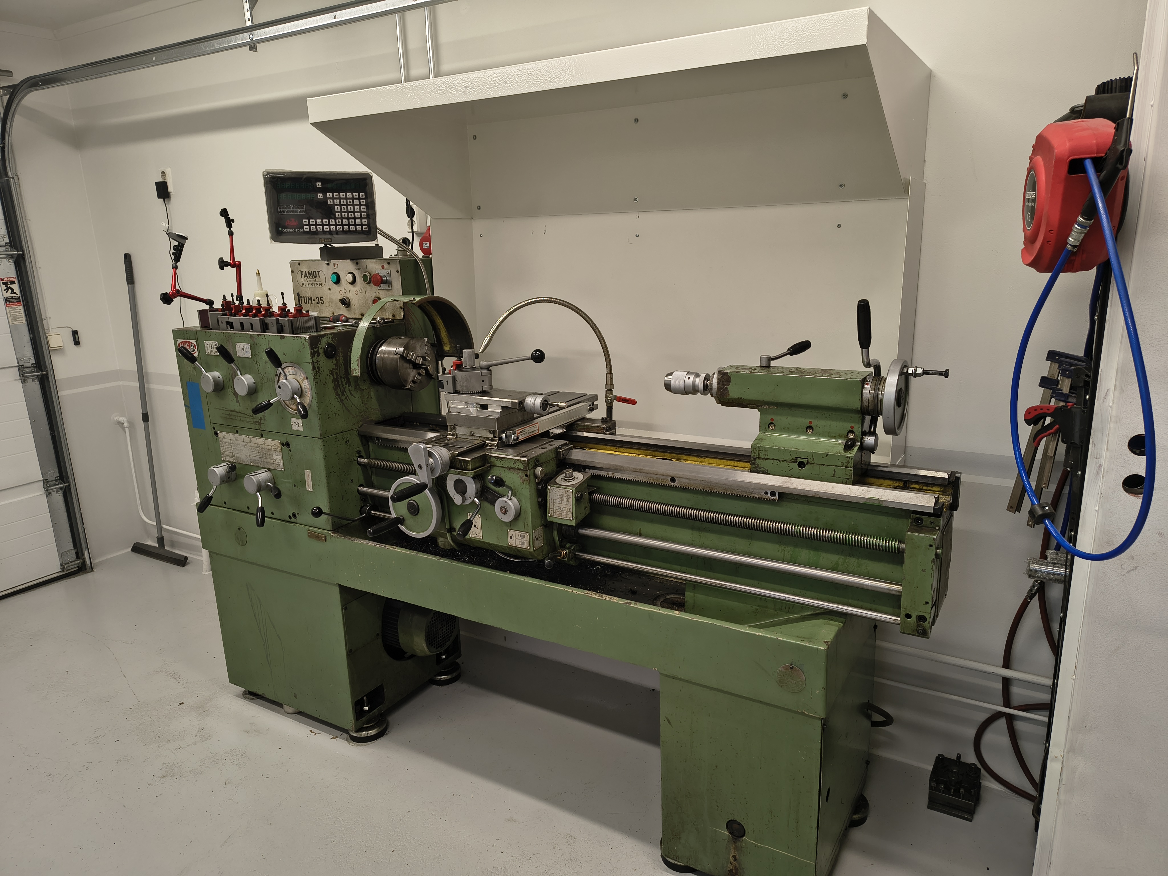
Installed rest of the digitals, Multifix, and got this rear shield made to keep the chips in the lathe’s tray. It’s Famot TUM-35, made in Poland in 1986. Turning dimensions: 1000 * 350 mm, weight 1300kg. Really nice machine this is!!
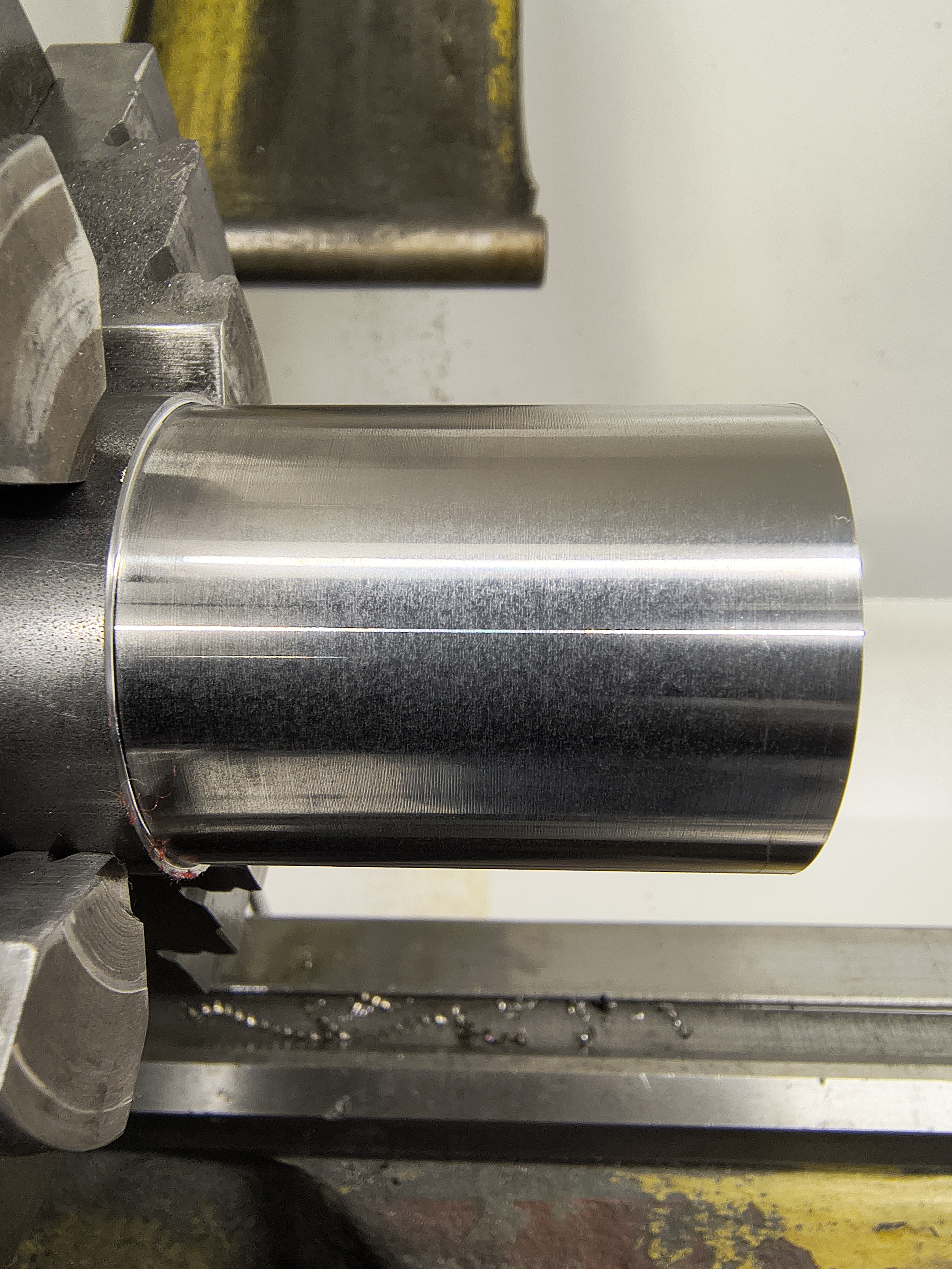
Nice.
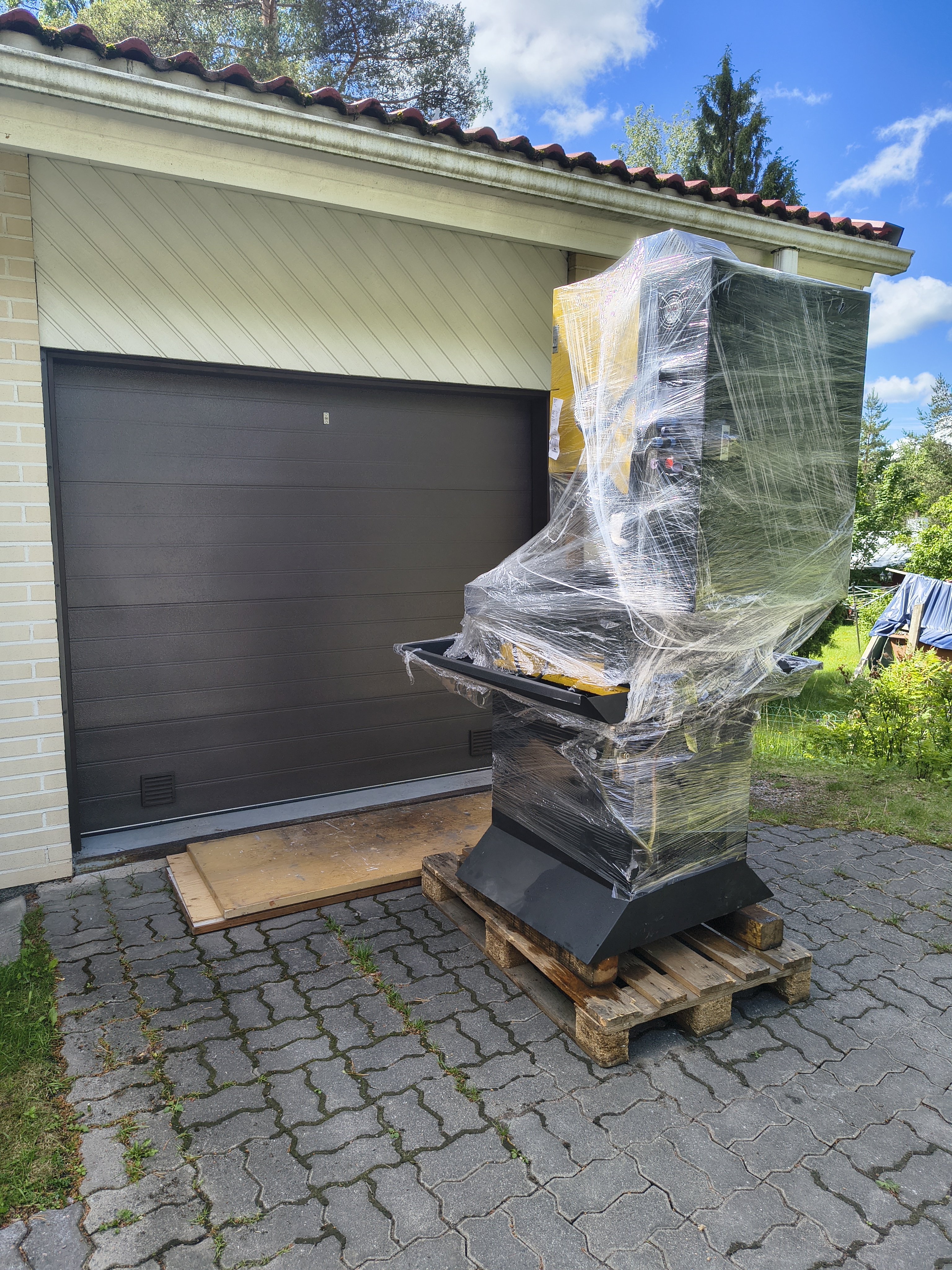
Got a sweet deal of this Syil X7 CNC milling machine. I was looking for a decent-quality compact manual machine, but those are hard to come by, if you exclude the bench-top models.
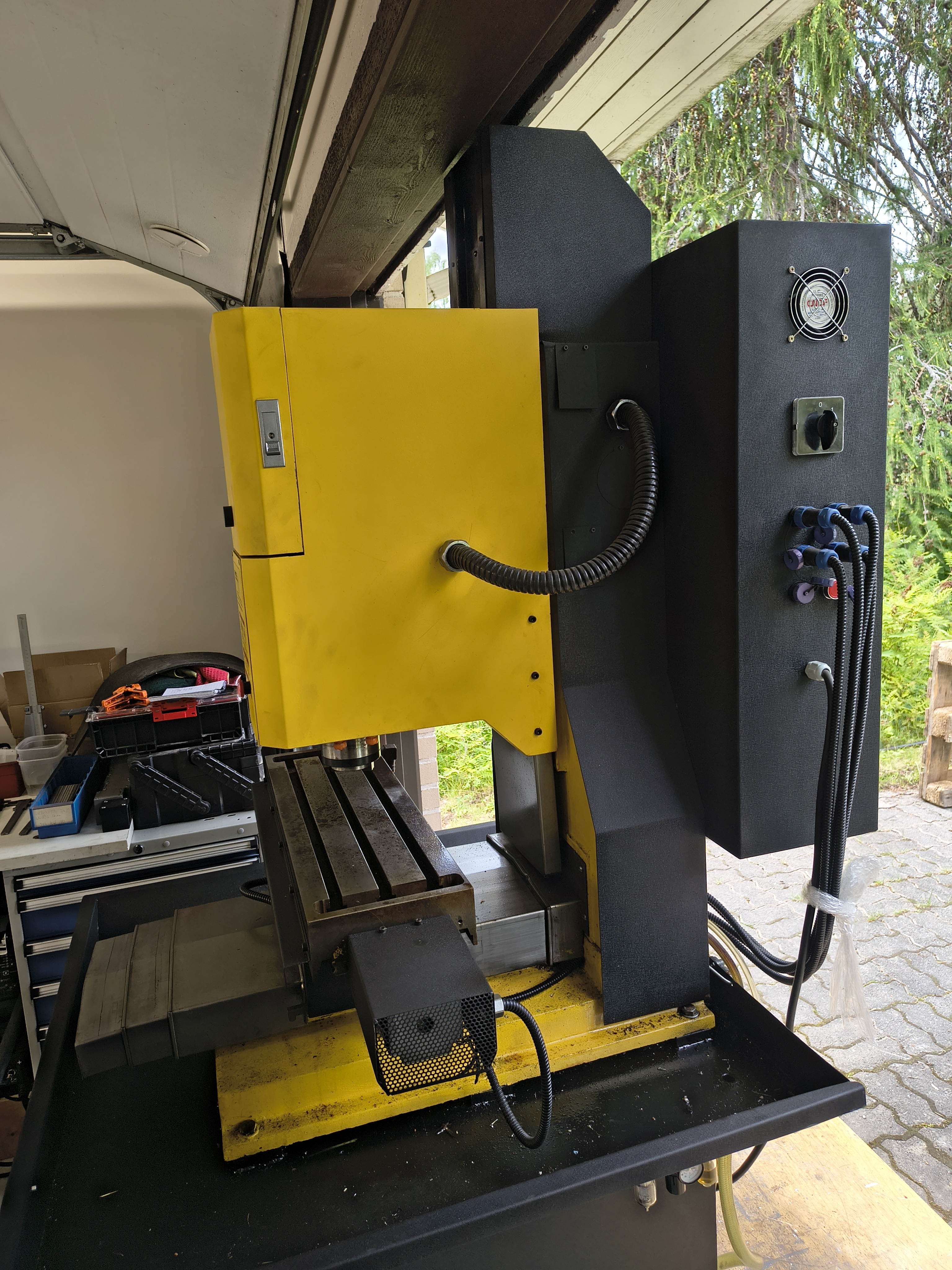
Let’s just say that if the machine would have been any taller, some disassembly would have been required (of the machine or the garage).
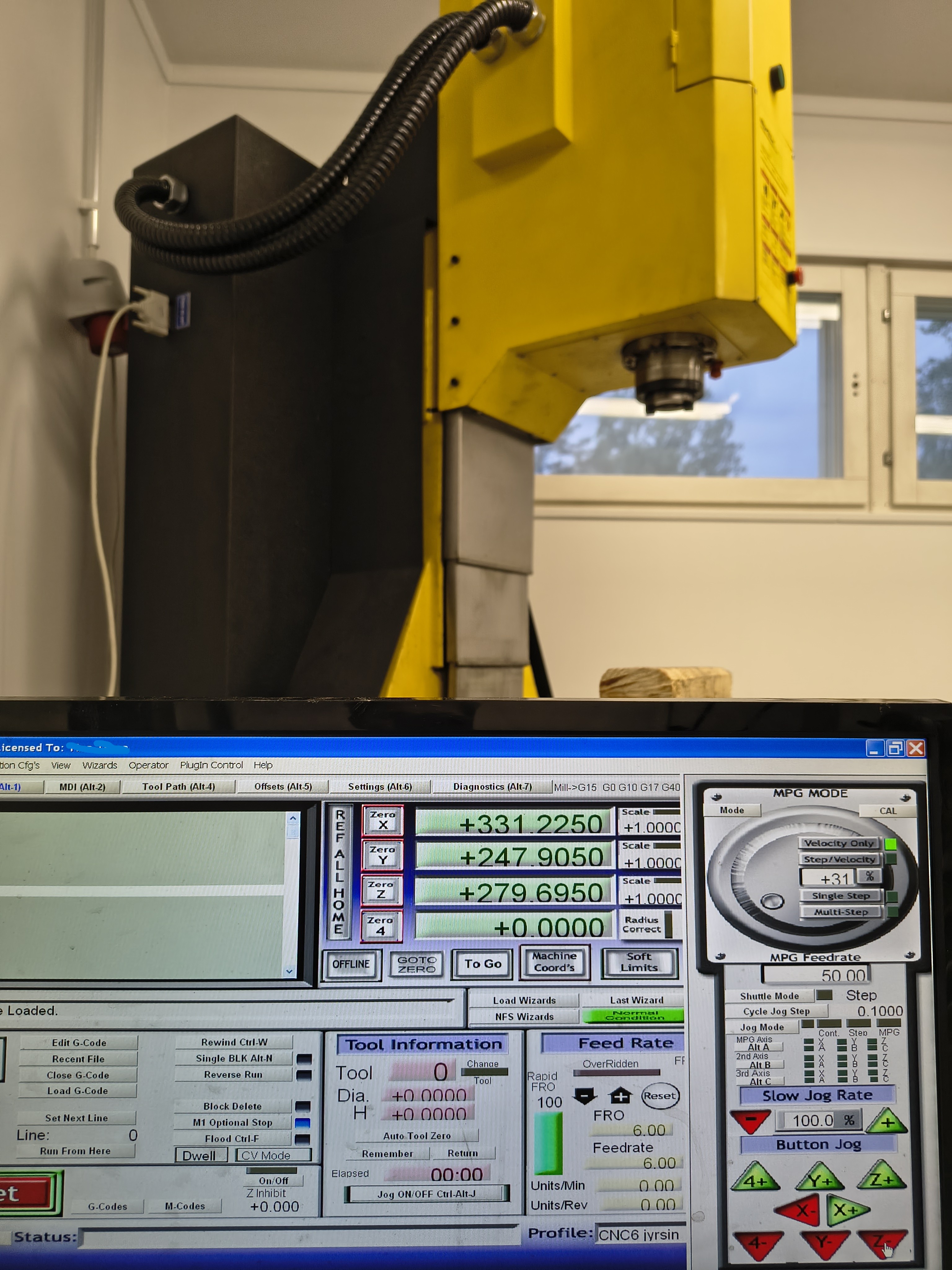
Powered by Mach3.
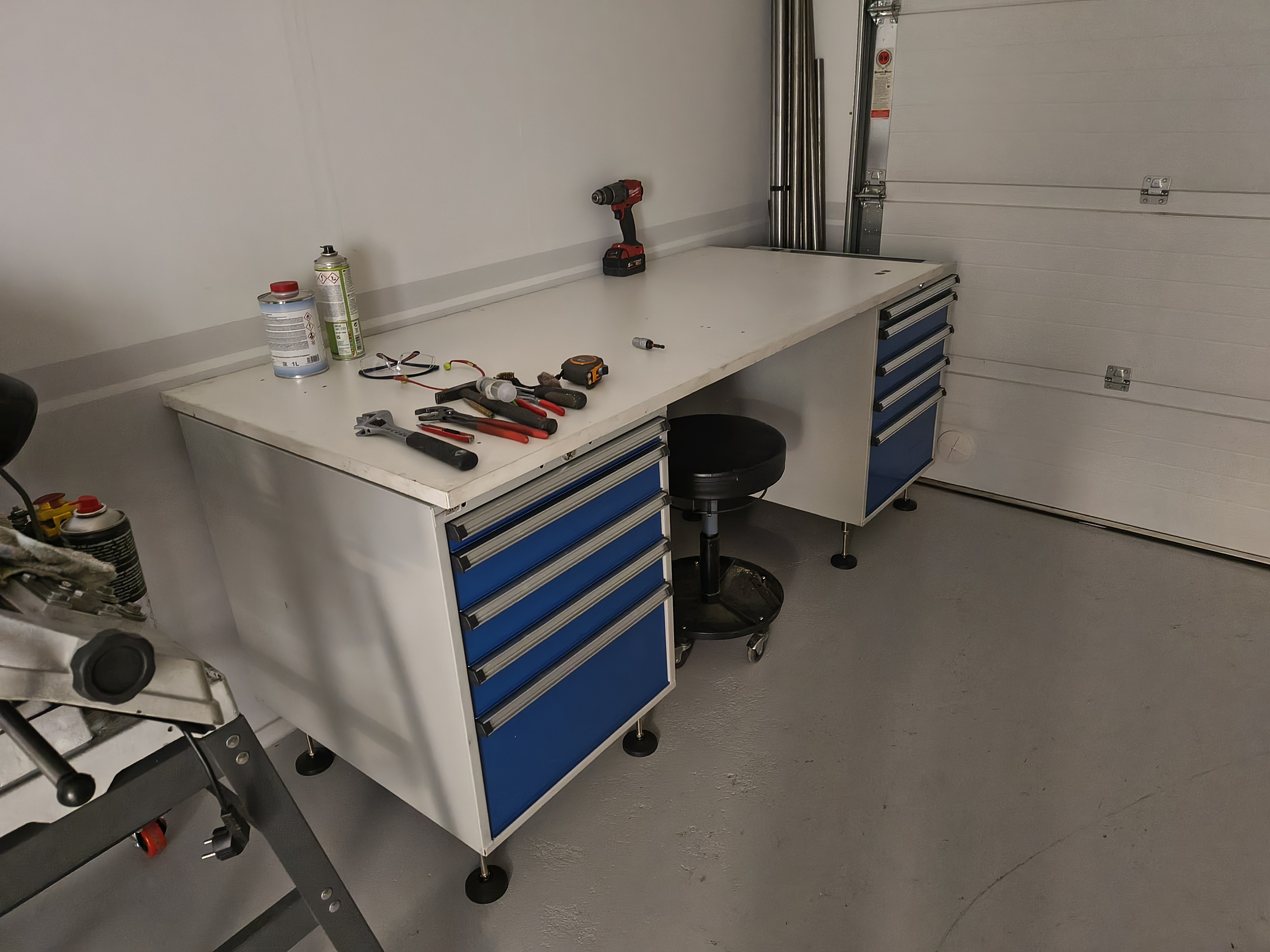
I had a hard time deciding what to do with the workbench.
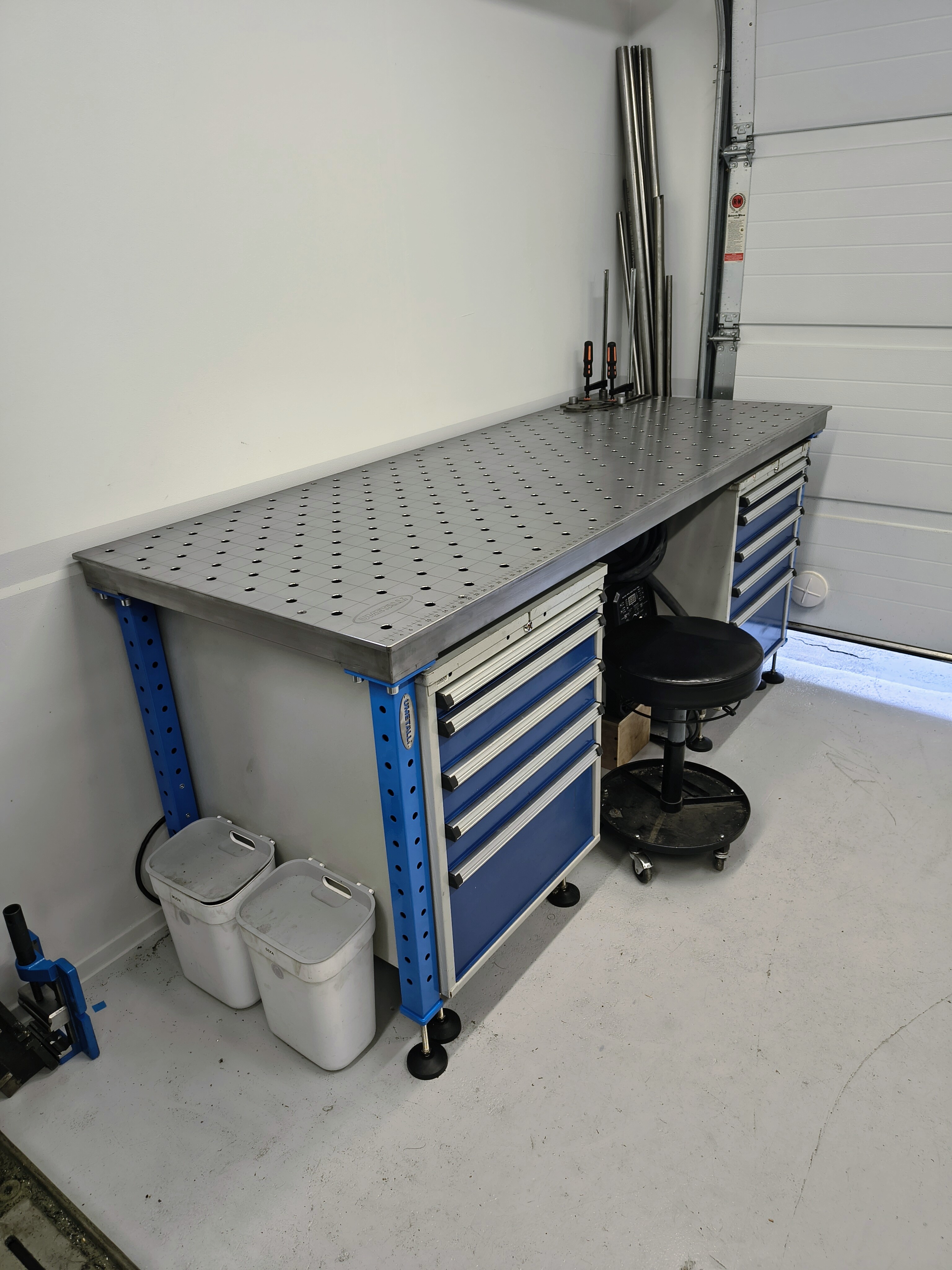
Then I found this 800 x 2000 x 10 mm welding table, from a Finnish company which was a perfect fit for me! Two-in-one table really for this small space! Well it’s not Siegmund or Fireball, but it was a lot cheaper
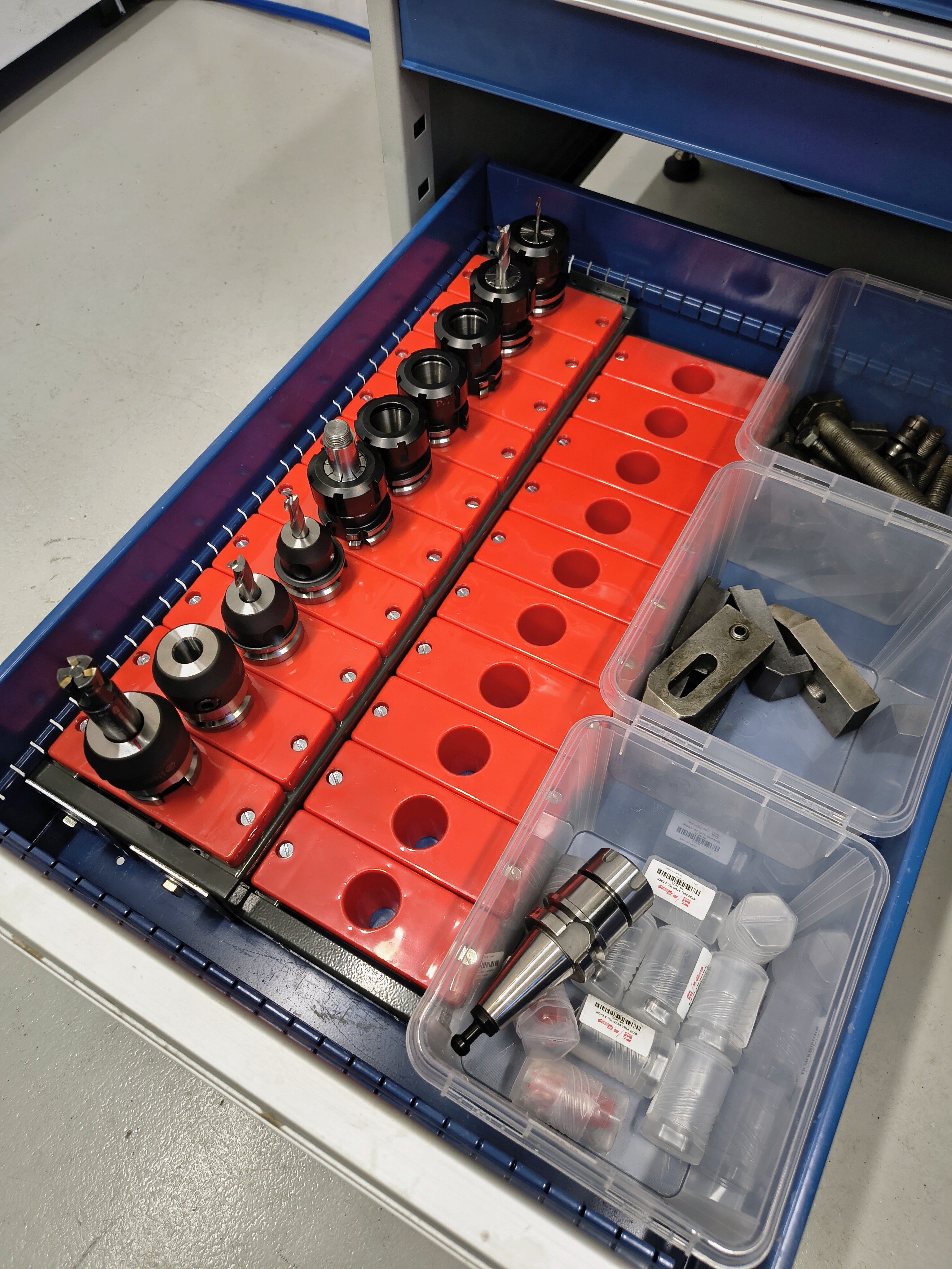
These GWS drawers are the tits! You can fit so much stuff, and they carry 80kg each drawer! Also Finnish brand
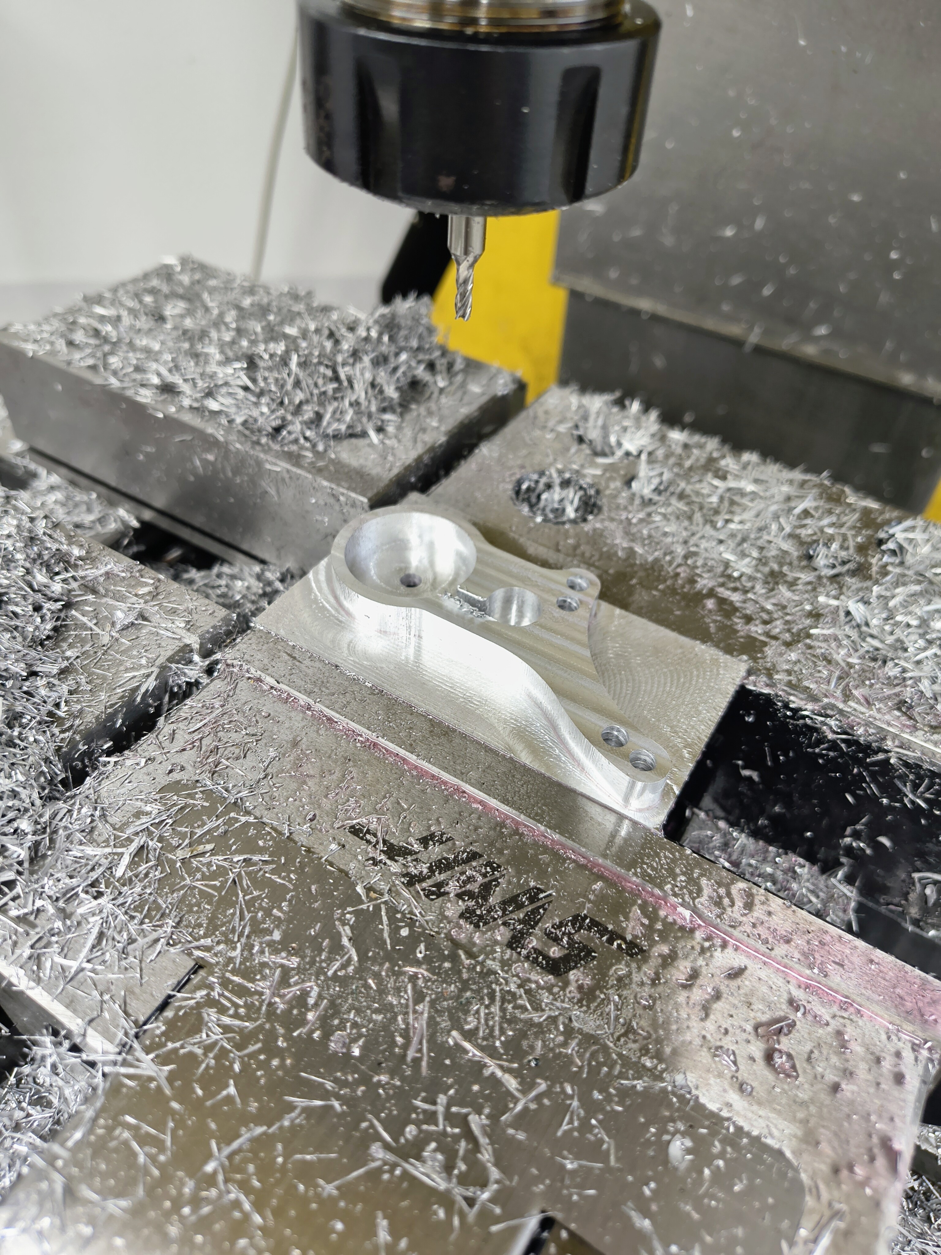
My first CNC part 
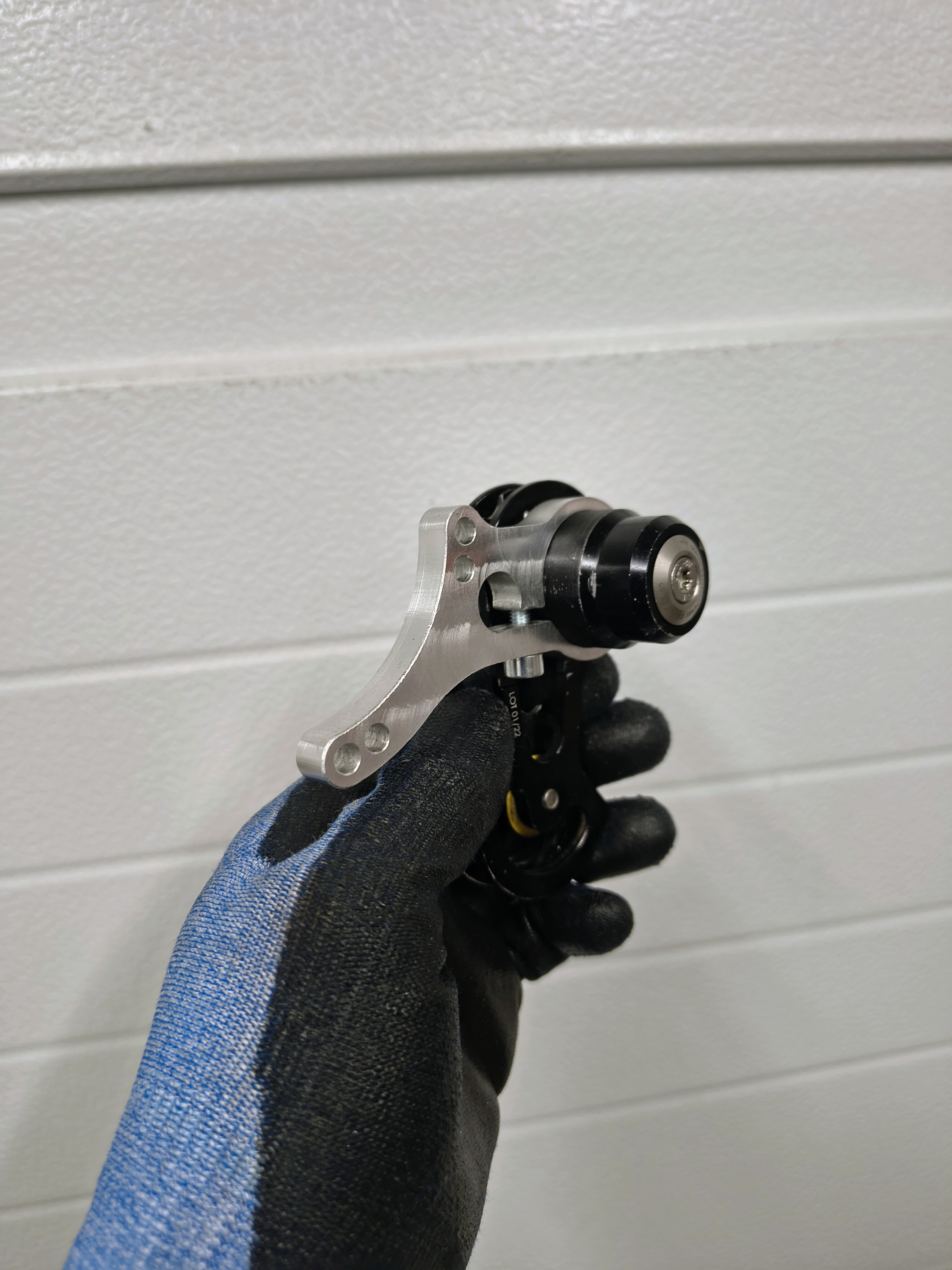
Bracket for Effigear 24T / Pinion tensioner.
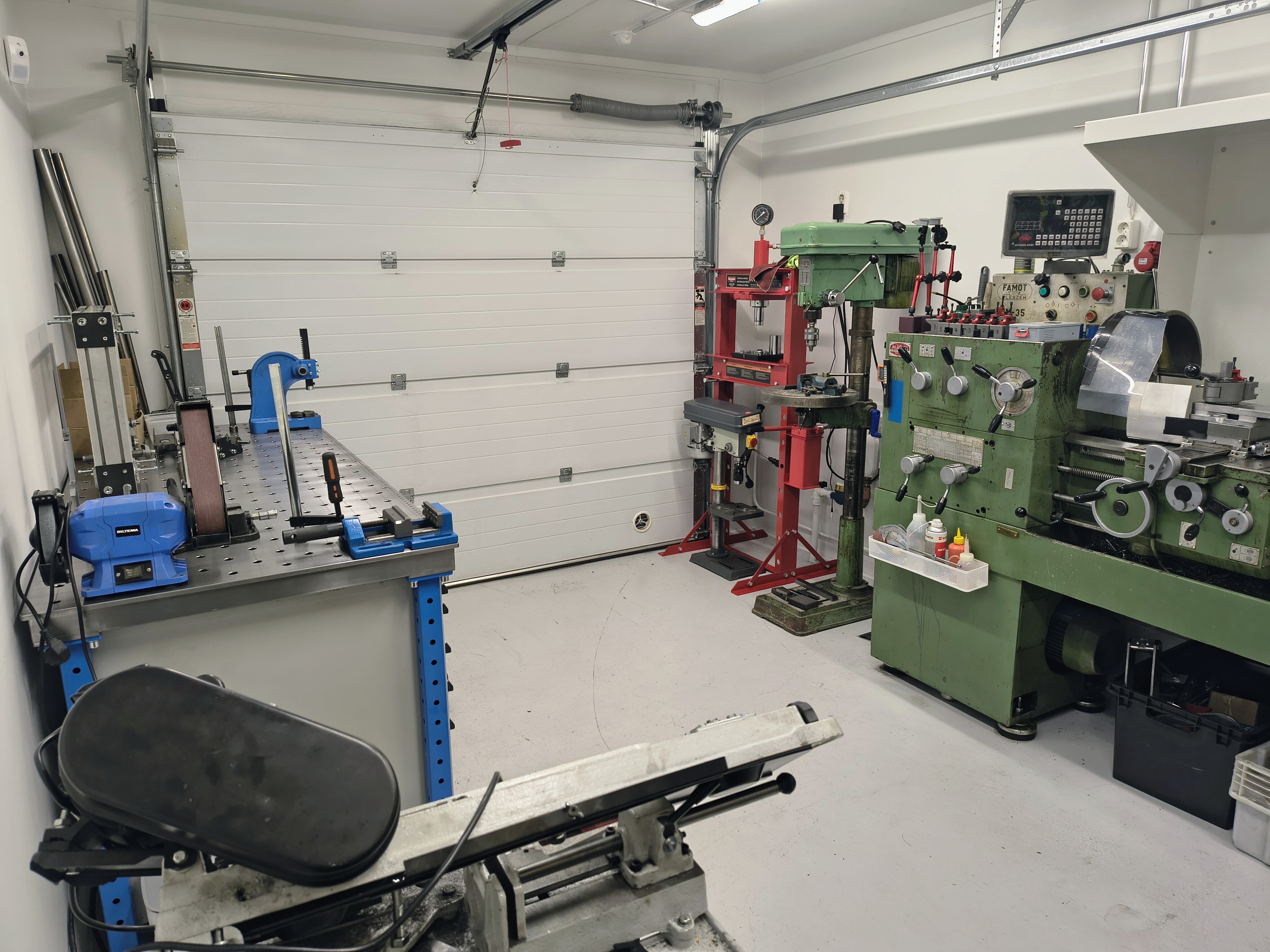
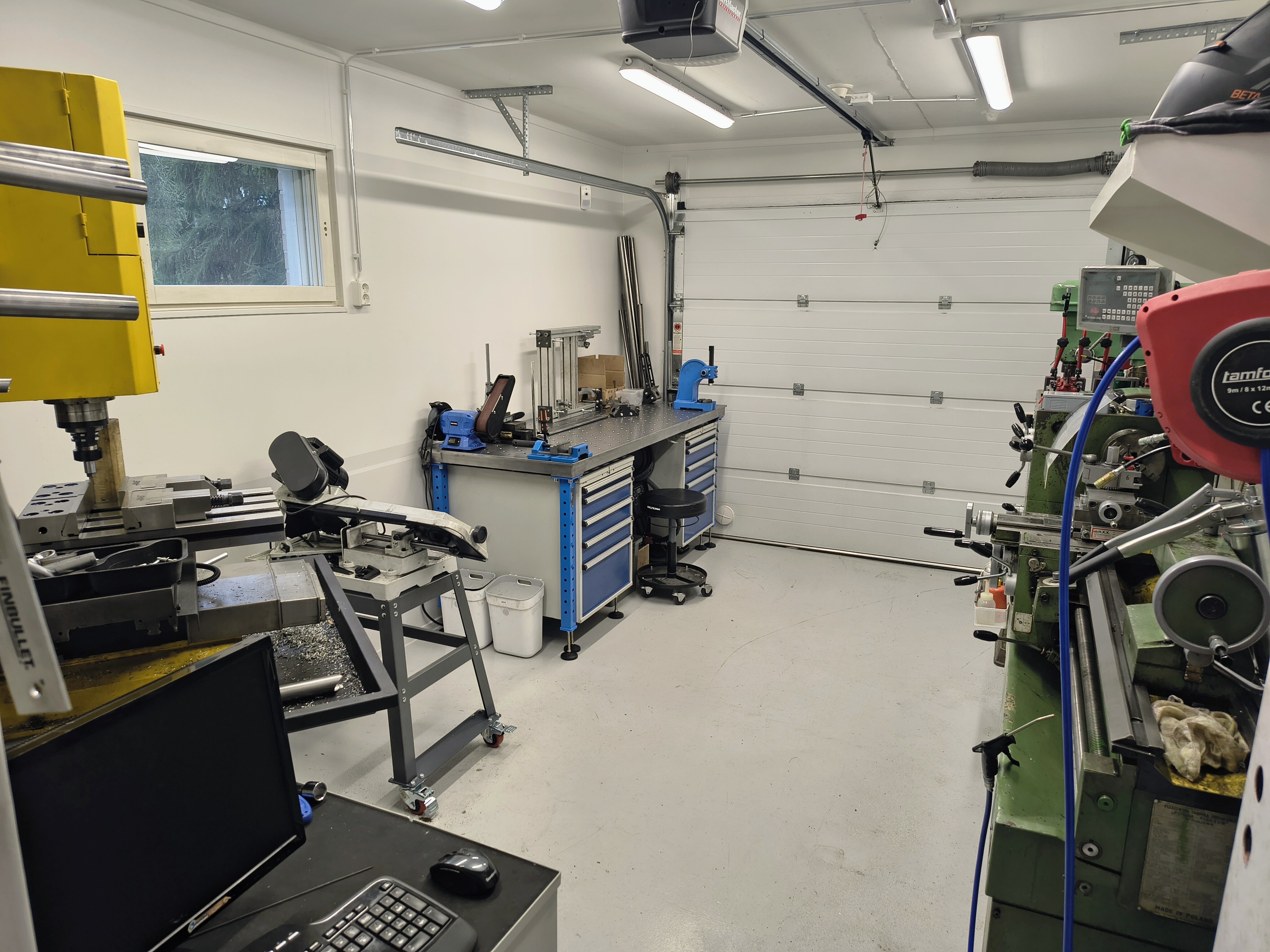
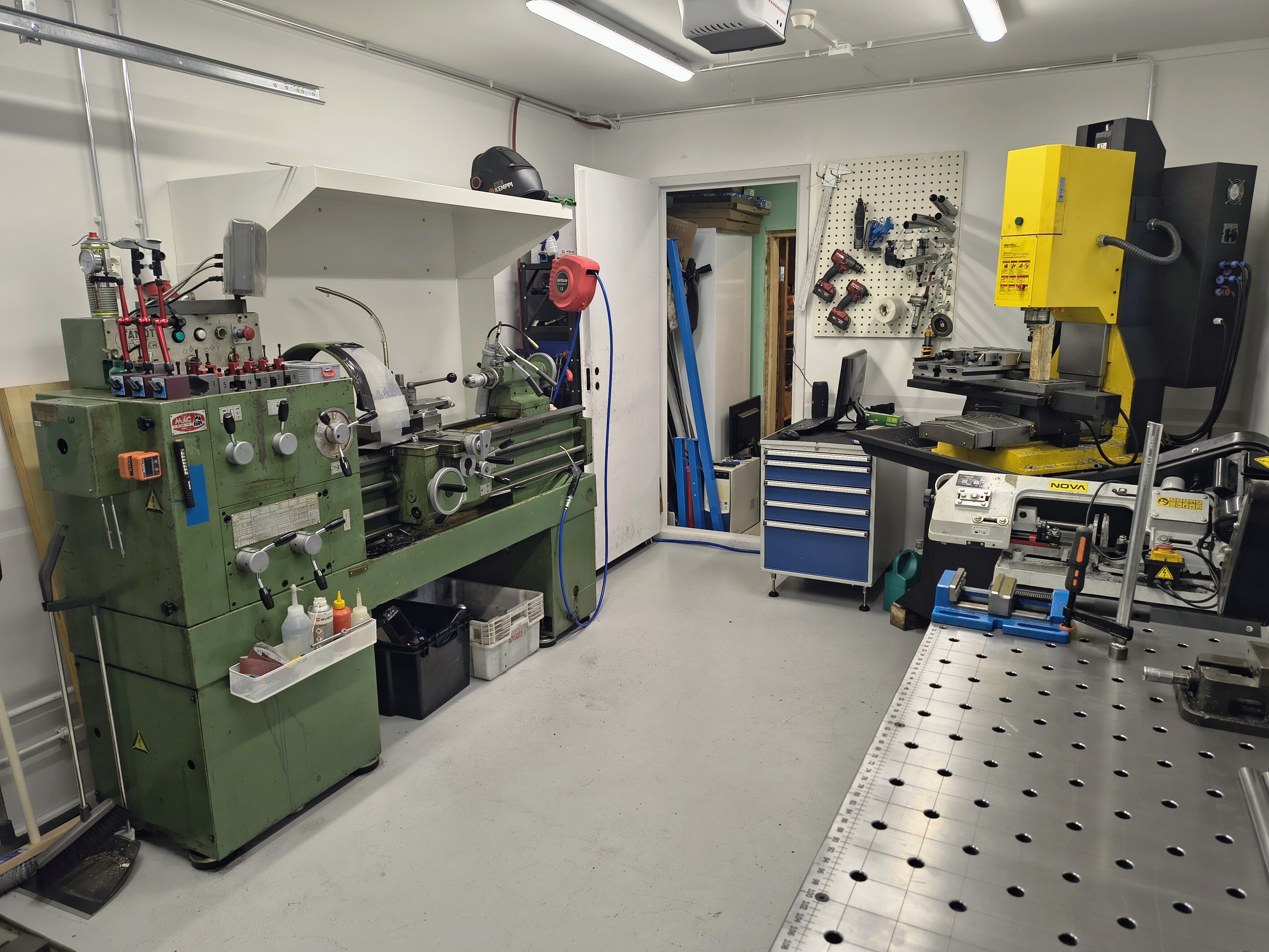
Here’s how it looks now! I’m close to having enough stuff in it right?
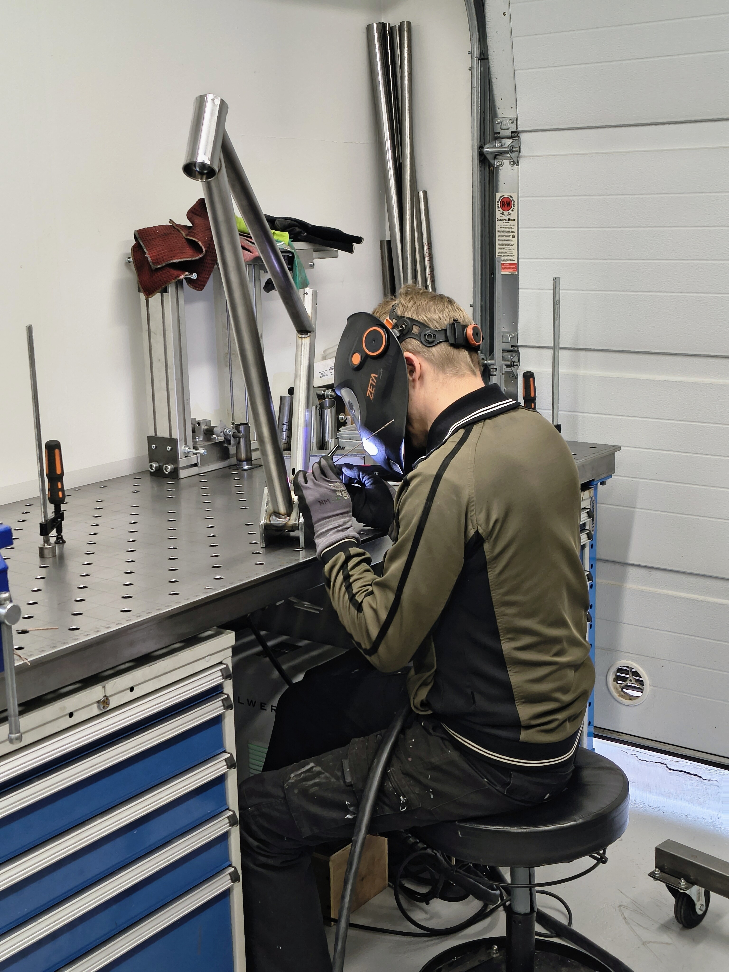
So nice to weld on the table, when you can rest your hands on it, and don’t have to worry about grounding.
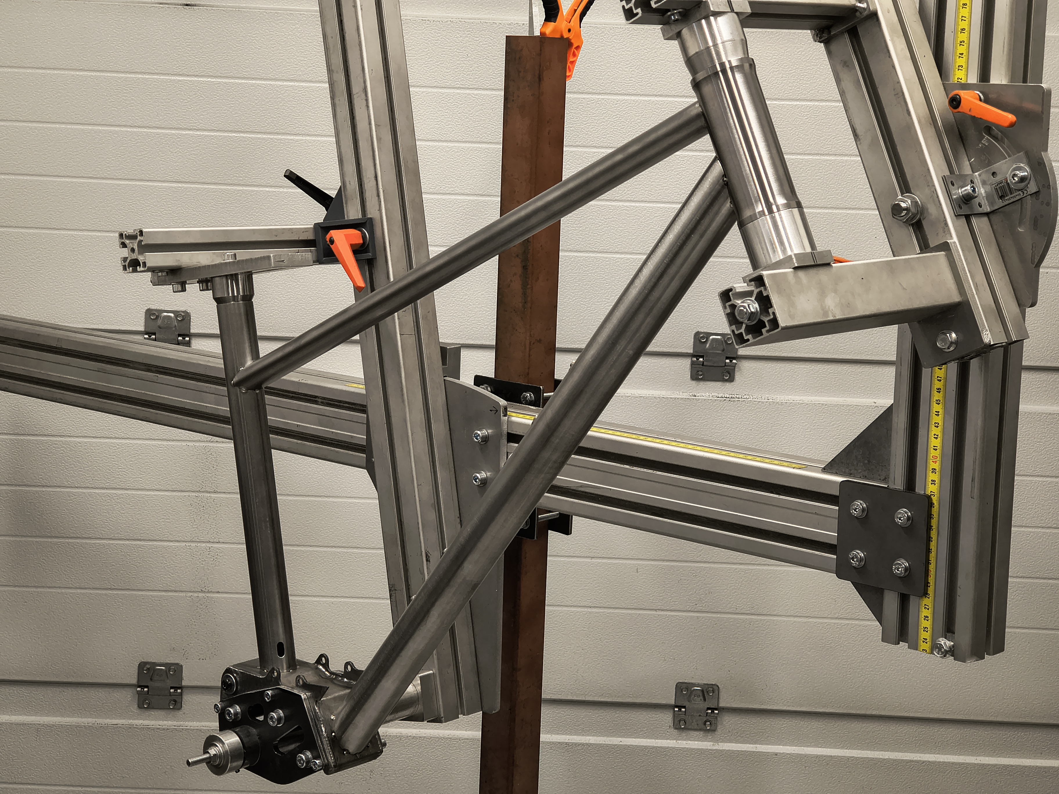
Well the jig was still missing I moved Olli’s jig in with me.
More about v3 on the next episode!
12 Likes
Nice mate. What a luxury after being in the apartment. Set up looks great too. Enjoy.
2 Likes
Let’s check the design of v3!
Design drivers vs. v1 and v2:
- better manufacturability
- more lateral stiffness on front and rear triangle
- more adjustability
- consistent and predictable kinematics
- no increase in overall weight
Manufacturability:
While manufacturing and welding v1 and v2, the immediate thought has been that “this is definitely a one-off, I wouldn’t want to make another one like this”. So the whole DFM idea was very strong on v3. This meant going back to sheet metal and CNC-machined parts. While the 3D-printed 316L parts look great, machining them and filing them to fit the tubes was a total PITA. And I’m still bit sceptic about the fatigue resistance on them.
(I’m not saying all 3D-printed parts are bad, I’m just saying as the v2 was my first go with them, I had more troubles with them than I anticipated. Of course this has a lot to do with the design itself, and one could account for better machineability in the design also. I’m sure they have their place and I will probably use them again in future projects.)
It may seem that the sheet metal parts are cheap and easy solution, but I think that easy manufacturing and welding makes for a better end-product, with lesser weld defects and better repeatability on tolerances. I’m not a great fan of “rally holes” on sheet metal, but I must admit they are cost- and time-effective.
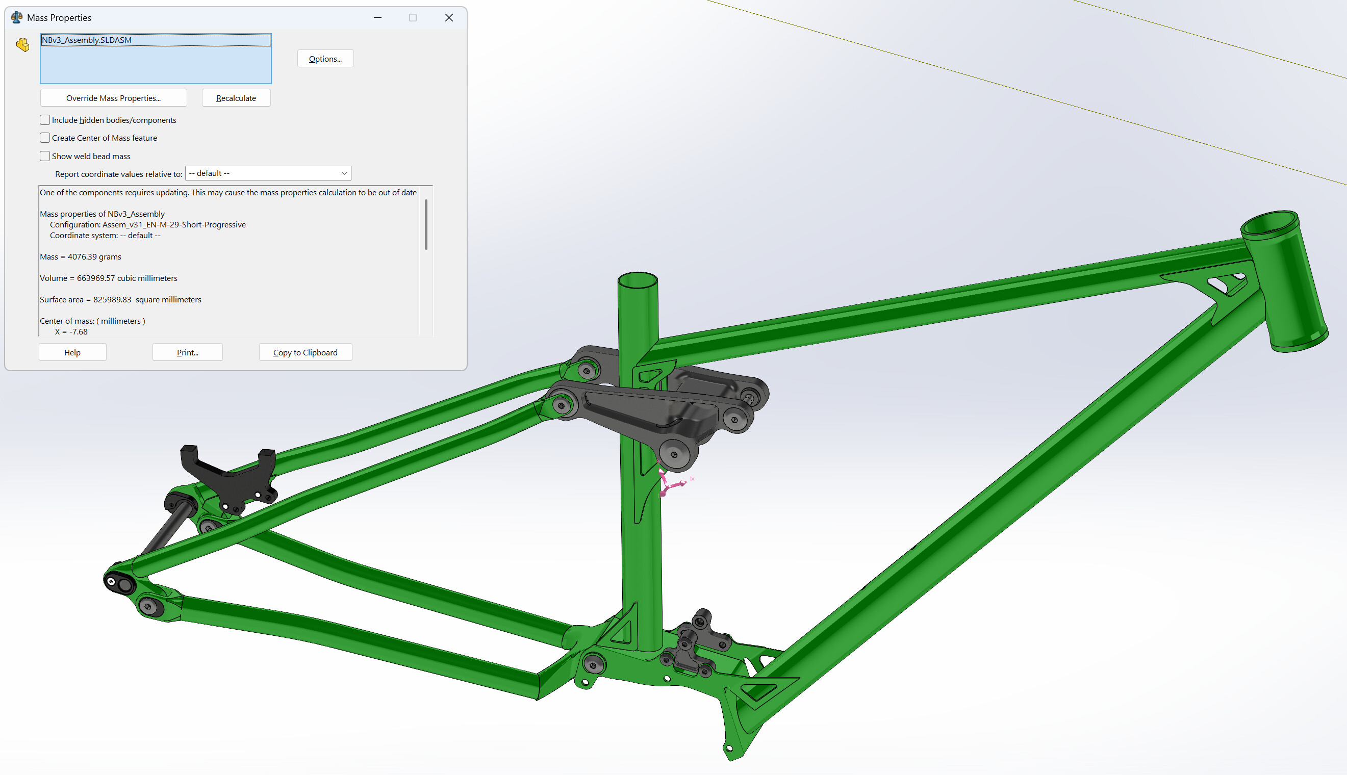
Size-M frame with all axles etc. at ~4080 g.
Stiffness:
Increasing the downtube diameter from the previous 35x1,0 Docol, I went to Velospec 38,1 mm on M-size and 42 mm on XL-size. I asked Reynolds about their 42 mm downtube in longer version, I don’t know if it is available at the moment…
I saw a picture of some XC-bike with a chainstay yoke that is not the traditional “H-shape”, but more of an Y. This design actually solved a couple of problems I had in v1 and v2, since it brings the mainpivot bearings in a prefect alignment inside the yoke, allows for more room for the yoke, since it essentially is “inside” the gearbox, and is also very stiff. Now, the new Cube high-pivot enduro uses the same design also, so must not be that bad.
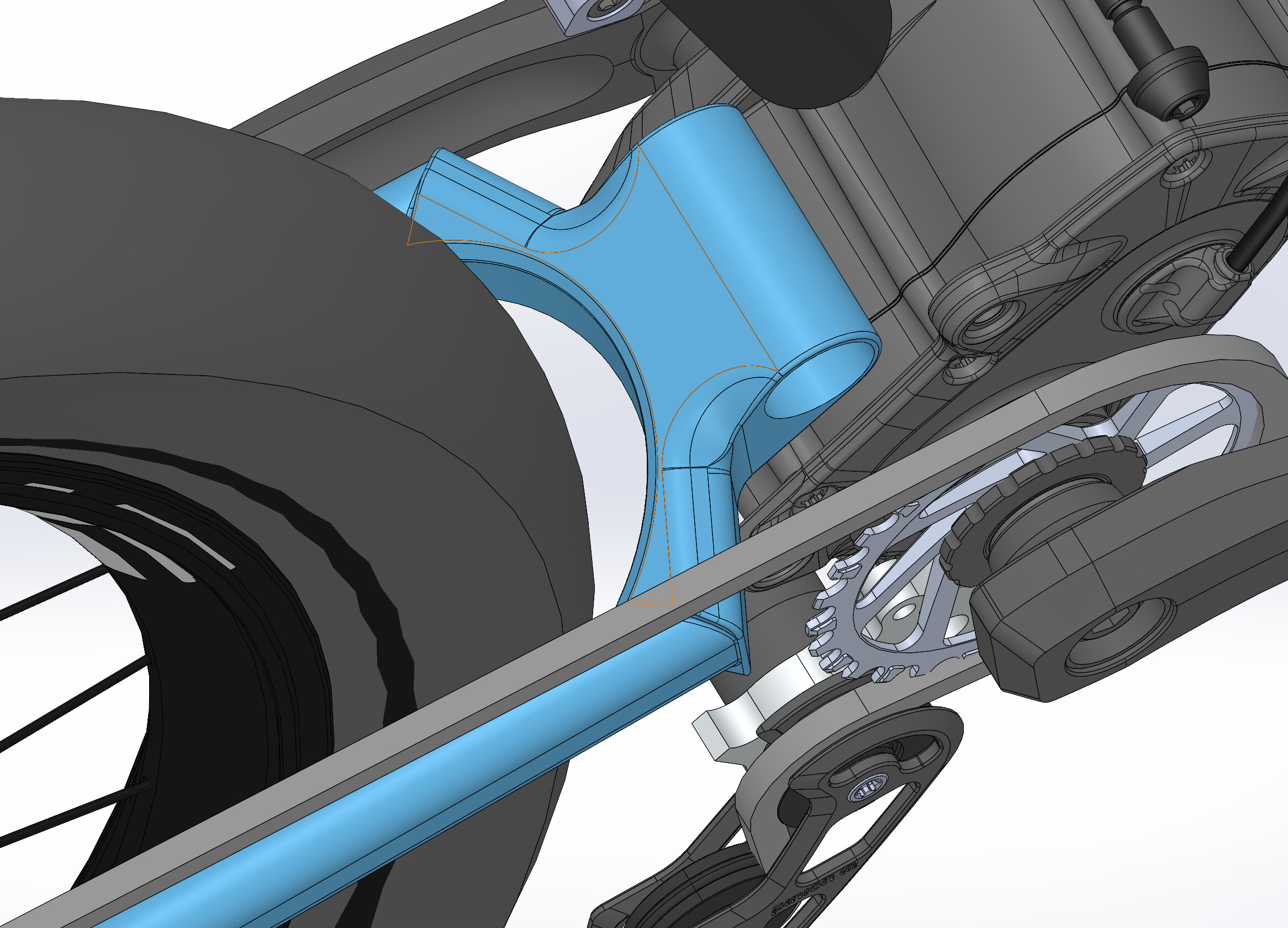
How the v3 design process started, the yoke sketched on top of v2 model.
Adjustability:
Previous versions didn’t have any geometry / progression adjustments built-in (except the v2 modular drop-outs which is after all a big task to make other versions). During the design, I got inspired by the new Orbea Rallon also, and I wanted to see if one bike could have the possibility to be configured as enduro and DH.
So eventually, where I landed at:
- removable shock mount:
- linear / progressive adjustment (flip)
- high / low adjustment (flip)
- enduro / DH configuration (change shock mount)
- chainstay flipchip:
- 27,5" / 29" setup
- rear axle flipchip:
- 0 / +10 mm adjustment
Also part of the configuration is the 44mm headtube, which helps counteract the ATC heights:
- EC44 for enduro
- ZS44 for DH
These settings allow for the travel to be between 162 and 200 mm, with basic settings being:
- 230 x 62.5 mm shock: Full 29" enduro, travel 168 mm
- 250 x 75 mm shock: Mullet DH, travel 200 mm
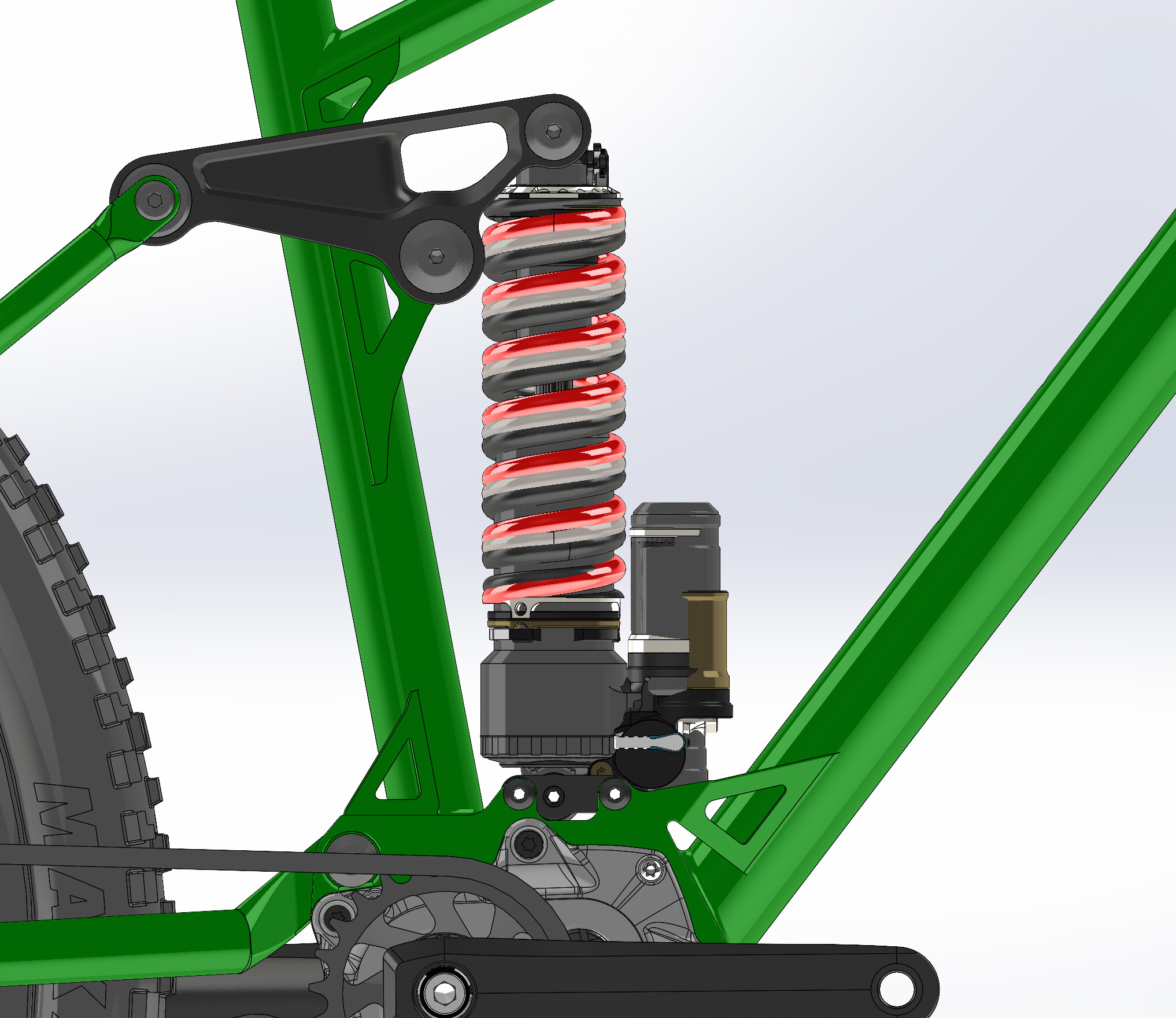
Checking “all” the shocks for clearance. Of course shock can be installed “upside-up” if clearance is not enough for some shock.
Kinematics:
Compared to v1 and v2, I think this will be improvement in all aspects. Well, Anti-Rise is a hot topic and cannot be optimized for every scenario.
Mullet setup has far better Axle Path, simply because the axle starts at a lower position, so it won’t be that forward.
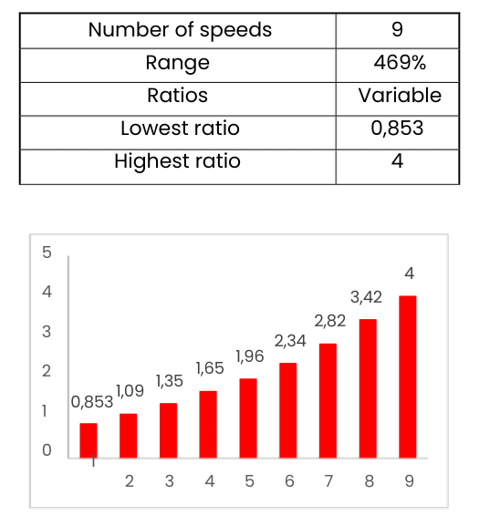
Effigear Mimic ratios.
One thing I realized recently, is that Pedal Kickback is not actually the same in every gear. Of course the gearbox will multiply this effect regarding what gear is selected. In Effigear Mimic, the 2nd gear (2nd easiest), is close to 1:1, therefore 1st gear will experience with more Kickback, while gears 3 … 9 experiences less. Just like in normal drivetrain. With my quick math the range will be ~ 29,5 … 6,3 degrees.
With my current setup and in my local trails which are quite low speed and sometimes techy, I can occasionally hear the DT Swiss ratchet “clunk”. So I know it’s there, however I don’t know if it really affects the performance that much.
Well here’s the graphs:
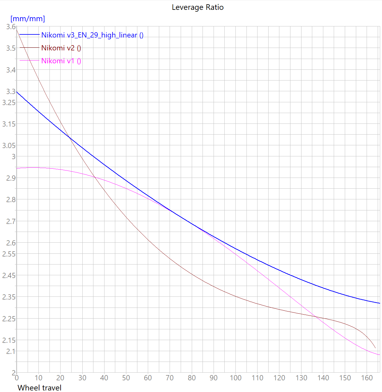
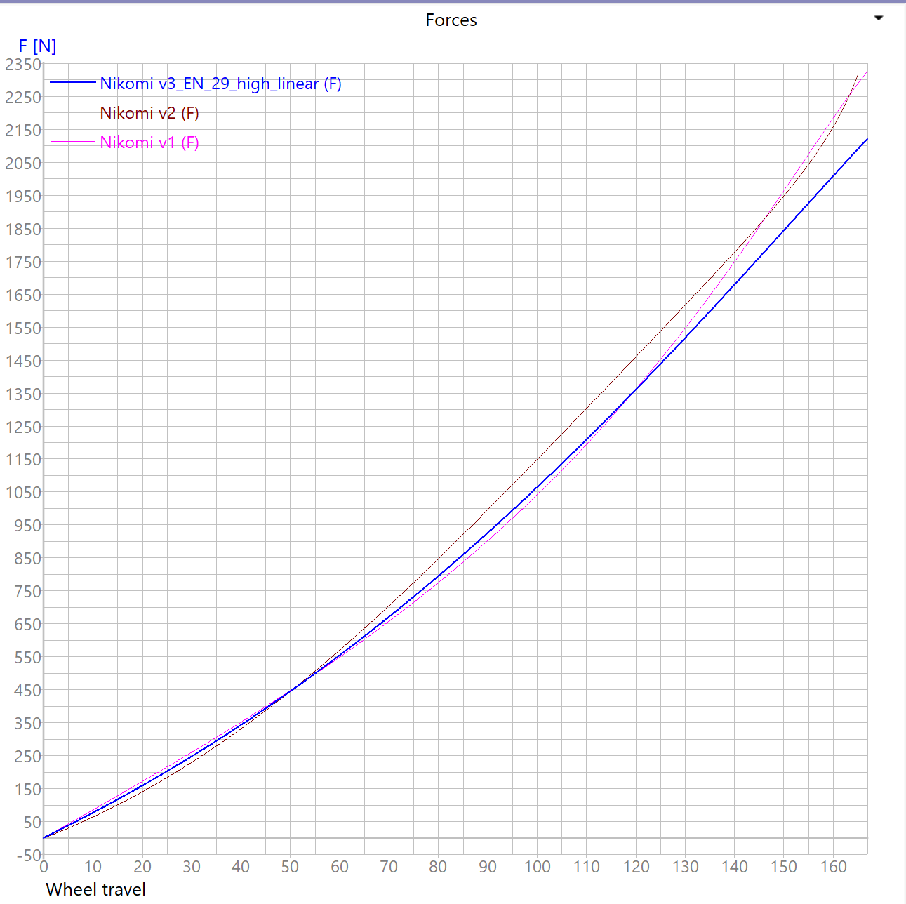

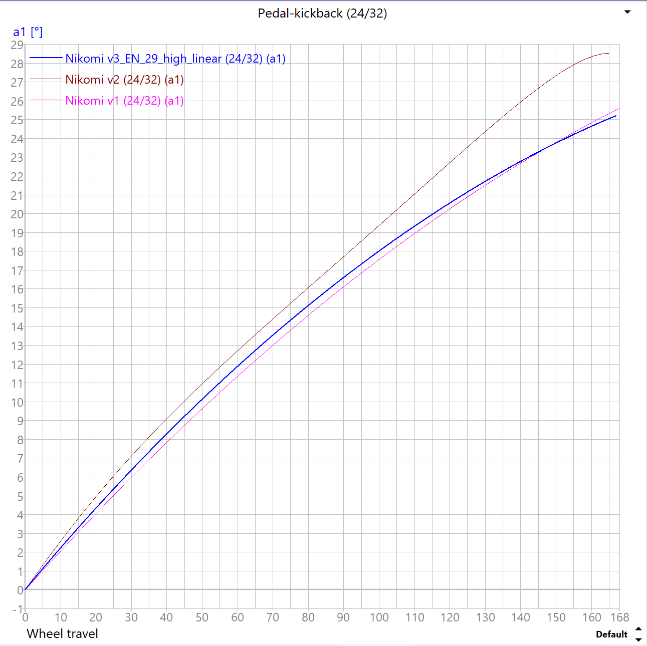
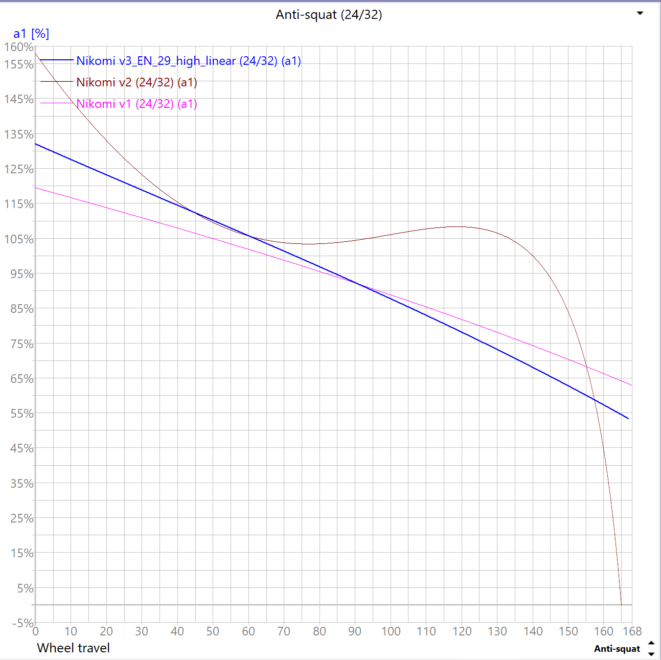
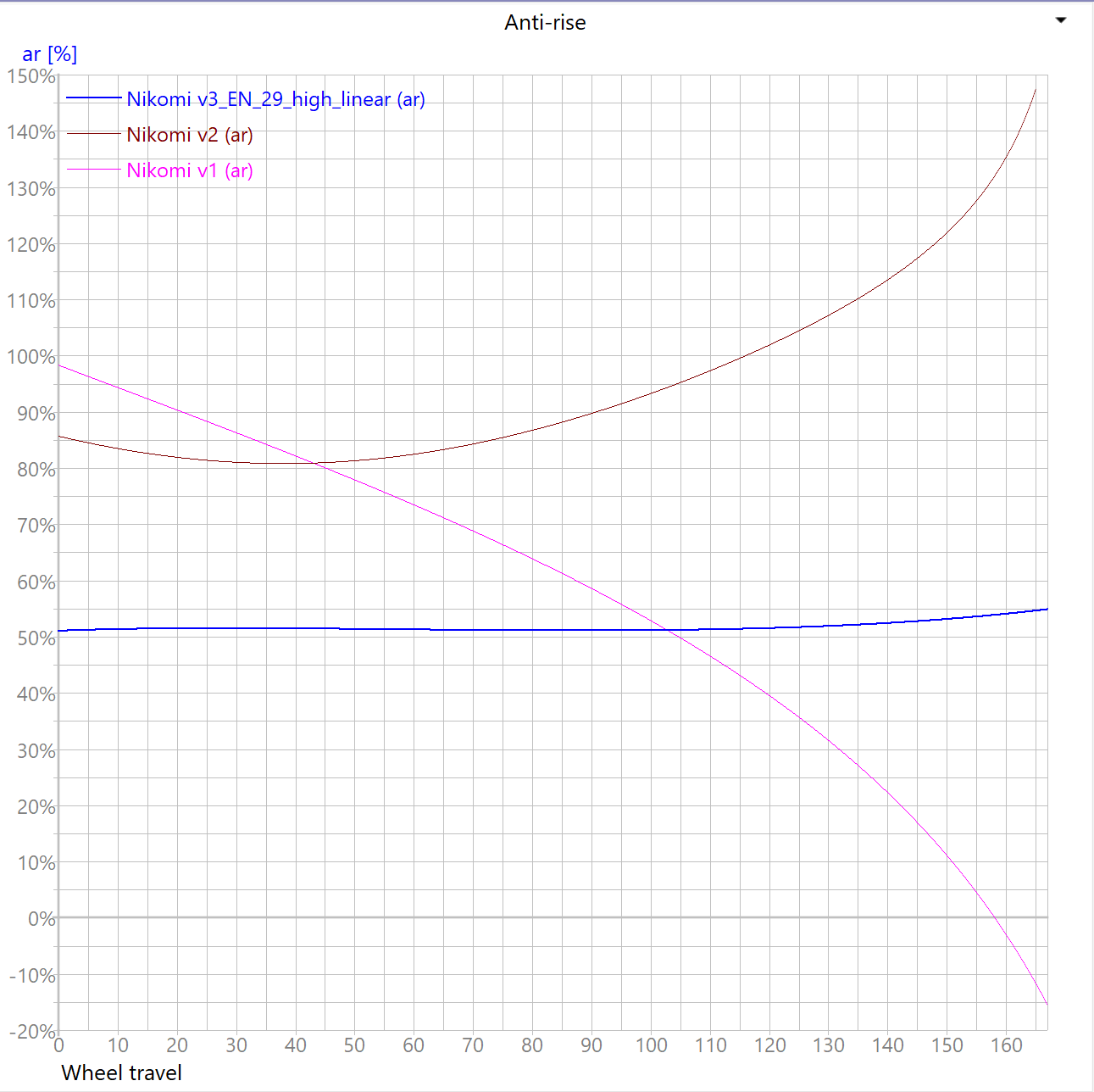
Surprisingly, the kinematics have very little compromises between the enduro and DH setup. Well, other than limiting the shock stroke to 62.5 mm on the enduro setup, rather than having the “standard” 65 mm.
Weight:
As seen in the picture above, weight for a frame set without shock in size M (reach 460 mm) is bit over 4kg. Which is not bad in my books for a DH-rated steel frame with lots of adjustability.
… about the “DH-rating”, does anyone know what is the price for EFBE-test? 
3 Likes
Nice write up. Lots of details in there. With 3D printing you have to allow for the ‘kerf’ of tolerance possible. If you have fits like tube onto spigot you need to go slightly undersized or allow for filing time. Bearing seats etc. need to be printed with extra material and plan to work hold to machine. The BB sections I get made I get the supplier to machine the threads and main pivot for me. Costs extra but then I don’t have to do it and it comes perfect everytime. For the BB threads I add an extra 3 mm of material as it also helps maintain circularity through the two heats cycles of making and heat treating. Some openings need struts or discs in the print to help with that as well.
I was quoted around US$3500 plus shipping to Taiwan for full EFBE testing last year.
1 Like
The issue mostly was making fixtures for the printed parts, since the parts did not have much flat surfaces, also they had some “extra” material from supports I guess. So in the end it was guess-work whether the part was squared in the vice before machining.
Chinese printing probably has better quality, which would have resulted in less frustration in my end.
Of course with billet-machining, you have to design the part for that process also, for example you cannot have too small inner radiuses, not to mention about hollow parts…
So in the end it comes down to what the part really needs, and what design route you take to accomplish that.
Well I guess I’ll have to build my own EFBE test rig then Sounds like a “fun little side project”
1 Like
Hmm, not sure if I would use Cube as a reference for bearing arrangements in general, their track record is quite abysmal in my experiece working as a bike mechanic 
Really nice design, and I support your thoughts on the additive components! Sheetmetal and some intelligent jigging is the way to gor for making >1 of a frame design I think!
2 Likes
That is an important point about work holding that others may miss so glad you mentioned it so others can learn. I design in surfaces and think about how I am going to hold it to machine. Fir example the head tubes have a surface on teh inside I can mount them on an expanding mandrel to be able to machine both bearing seats in the lathe. I haven’t seen how they hold the BB shell when they machine the threads and main pivot but it definitely is super accurate. Cups spin in so nicely and bearings press in perfectly. Because the heat is applied away from those locations I can maintain the tolerance etc.
For the drop outs etc. the plan is to get work holding 3D printed and machined so it is really easy to quickly machine the parts myself and save some cost over a few bikes. I’ve had some success in 3D printing in plastic but it softens with the heat generated with maching. Having some coolant would help there.
I am thinking of making my own testing jig but Baum Cycles here in Australia is setting up a testing lab that I may just get him to do it. I will chat with him about it at Sea Otter.,
1 Like
Haha maybe you are right What I wanted to say is that the design came to me already last year, way before the Cube was out 
Having owned a Cube, maybe the design and quality in general was ok, but the bearings were the cheapest you can get, and quite small in some places. But you can find tiny bearings for example in Orbea and Specialized also…
1 Like