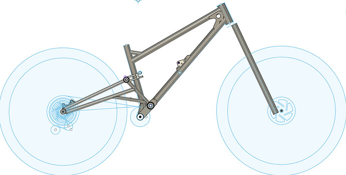
38.1 x 0.9
200 mm
150.6
Do you mean 38.1x.09? That is what your CAD looks like.
Tyler of BTCHN bikes uses a 38x.09 DT that is bent on a 6in (152mm) CLR. with a >50deg bend, so I know it’s possible. If you poke around this article, he mentions he found a place to mandrel bend the downtubes.
Yes 38.1 mm.
I should start the build thread soon, slowly getting the jig together and my lift arc welding is a little better.
I’m thinking about adjustable height dropouts, so I could use 29 and 27.5 rear wheel, but cant find much inspiration. Maybe you guys got some nice pictures/models/drawings? Would like to find a model or measurements of something like these so I can figure out my own design. I have no idea about the disc adapter location.
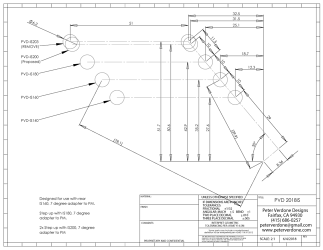
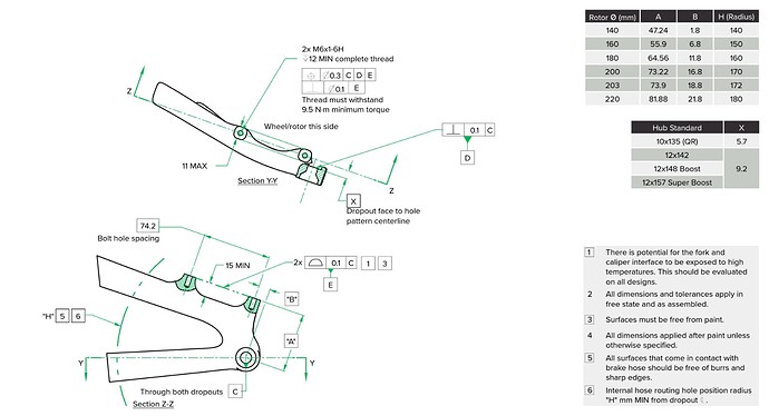
I have managed to find one IS mount standard drawing, is this correct? Would love to find post mount drawing. I can find Shimano drawing, but it has some measurements missing.
I have found that trying to design for multiple wheel sizes or purposes is generally a bad idea. You design in compromises and the user rarely (if ever) actually uses the extra set of wheels to use in the secondary configuration. Then they (you) are stuck with compromised primary functions. It seems logical but, just never seems to play out that way.
I agree with the others…This is definitely NOT KISS!
OTOH, maybe full sus is more forgiving of misalignment and geometry errors so, why not!
Post up pictures!
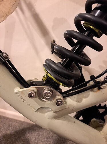
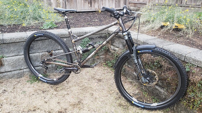
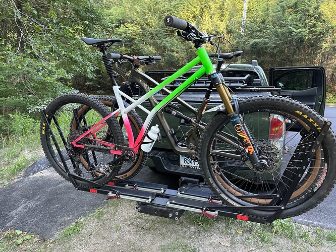
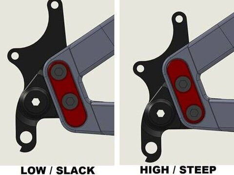
I made a shock mount with replaceable plates. increasing the amount of offset on the plate moves the rear wheel up or down. I got a few different offsets laser cut and will probably use the concept on all my full squish bikes in the future.
It was very useful when I realised that 330mm was too low a bb height for a 160mm travel bike. So I swapped out the plates for more offset and put a longer (180mm) fork on the bike and now its around 345-350mm ish while retaining the geometry I wanted. So thats pretty good.
Don’t pay them to do it for you, pay them to teach you to do it yourself!
My last design also has starling style replecable plates. And I designed the new frame with yoke driven shock, because I could not find anyone to bend my downtube and this is the only way to get >10% progressive leverage rate. Playing with the yoke and plates (sacrificing a little progression) should give me plenty adjustment. No idea why I was thinking about adjustable dropouts. Seems like every 2 days I change my design hehe. I’m aiming for 340mm bb height with 170 cranks.
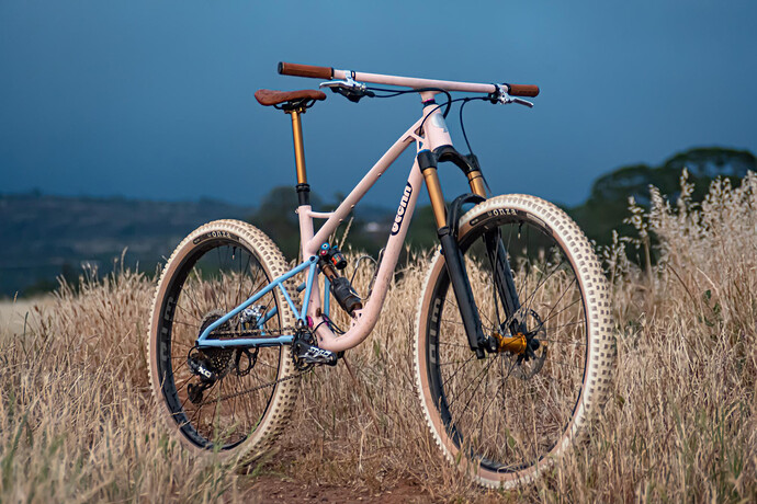
Everyone likes pictures:
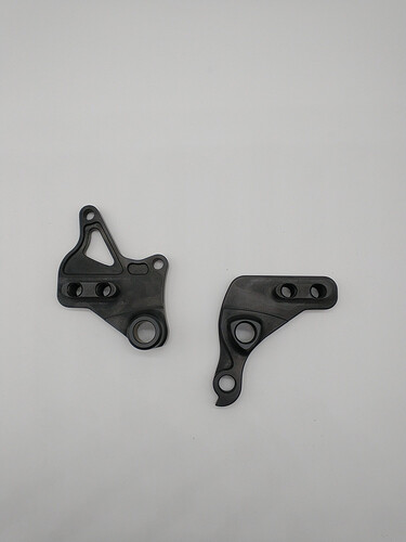
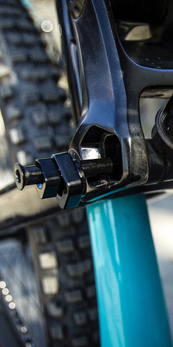
I have always liked banshee’s dropouts for wheel size adjustment:
With a plate steel dropout, you don’t even need the flip chip, you can just bolt it through different holes:
Once I saw a flip chip style dropouts that had 4 positions. Can’t find that bike anymore. It seemed like a vey good design. Looked like a rectangle with hole in one corner.
I have used the Banshee dropouts on a frame I build back in 2018.
Recycled them and the chainstays into the frame I did last year.
They were easy to work with and have worked well. I just drilled holes in flat plate and bolted them to the plate. The SS and CS are tab brazed to the size of the plate. The only struggle with using these in a brazed frame is getting enough heat into thick tab and not cooking the aluminum dropouts. Wish I had a tig machine to tig tack in my ghetto jig then braze the plate up with the drops removed.
Here is some inspiration on how to get around the need for a custom bent downtube.
https://www.instagram.com/p/BplWzf2A_wn/?img_index=1
https://www.instagram.com/p/Cty_li3OMAF/?img_index=2
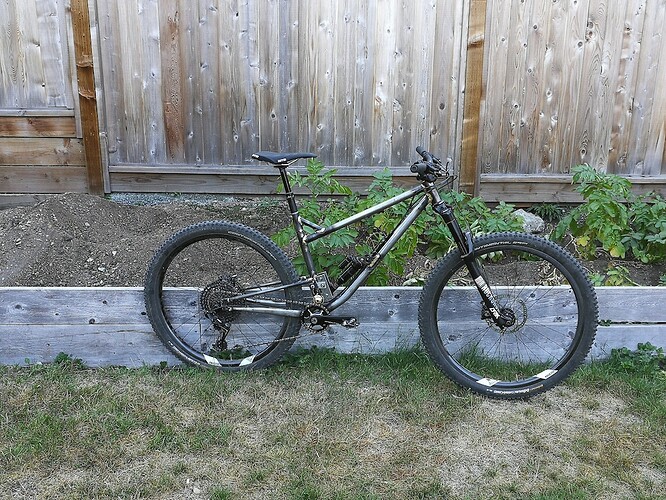
Marc built this frame back in 2018. A classic single pivot with 8% progression.
I’m pretty sure Andrew at Bike Fab Supply can bend 38.1 down tubes. I know Nova used to carry pre bent dt but doesn’t look like they’re a thing anymore. I did find this…
Little more time on the googler might net you something better. Pretty sure Dawley Bikes cuts, miters and brazes his DTs for clearance.
Yep I’ve done that. It’s not an easy joint to weld or braze and one that has to be done right. I’ve never been able to break one and always added a bracing tube. However I’ve never done any extensive testing and the frames were intended as prototypes to test suspension layout.
Tubecraft is the place a lot of builders here in the UK use. They can bend 38.1 x0.9 4130/ T45 etc and they produce a really high quality bend. Might not be economical for a one off and your location though.
Andrew at bike fab bent the down tube on my full suspension, 38mm 1.2 wall straight gauge. I think he still does custom bends if you send a detailed drawing.
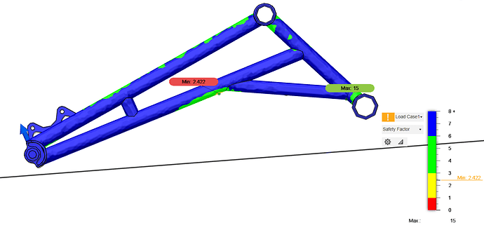
I’m fiddling with Fusion static stress simulation. How many of you guys use simulation? What kind of “results” are you aiming for?
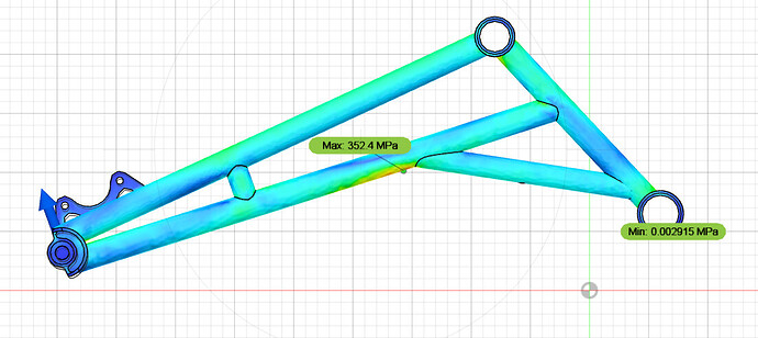
This is 2000 N force to the rear axle. It is the weakest spot on the whole frame when vertical loading. Main frame is considerably stronger. Should I increase the tube diameter? My rear triangle tubes are 22 x 0.9. Does this result show anything or I’m just wasting my time? Seen so many skinny tubes that I might be overbuilding.
Or considering that Columbus 25CrMo4 Ys is 760 MPa it is fine, because with 3000N I get max 352MPa strain?
Nice! I use the simulations as a sanity check. I would not trust the numbers unless I had spent a considerable amount of effort setting up the FEA (see Garbage in garbage out)
22x.09 should be strong enough based on what other people have been using.
Frames never buckle immediately (tube goes past yield strength), unless you severely underspeced the tube. If that were the case, the frame would be extremely noodly.
Frames either fail from a catastrophic event (landing to flat, riding into a wall) or fatigue. Using stronger tubes or distributing the stress better reduces the stress on the steel, which keeps it under the fatigue limit (Fatigue limit - Wikipedia)
Side note, that is a pretty cool dropout. Is it custom?
