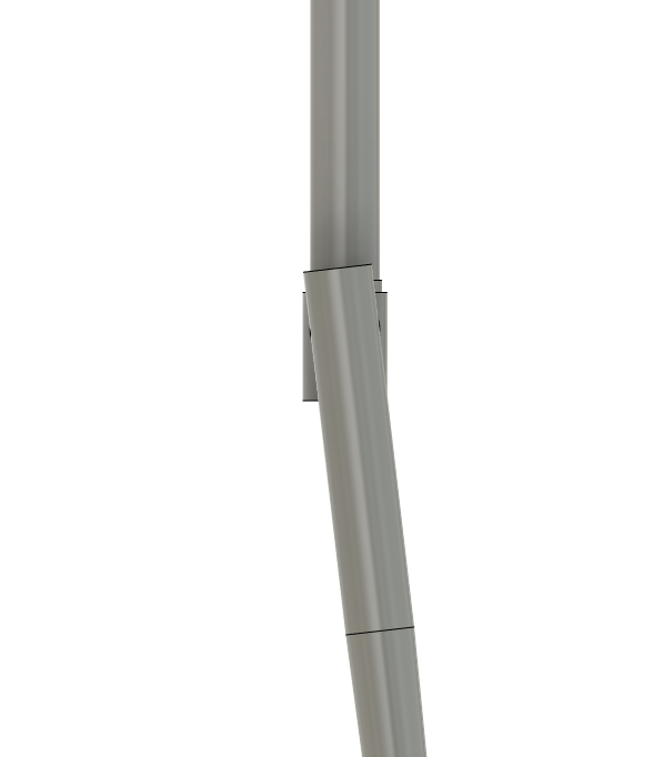
You are probably right, it’s because the top of that leg is not intersecting the center of the steerer. But of the top of the leg were on the centerline, the leg segment would be offset relative to the steerer.
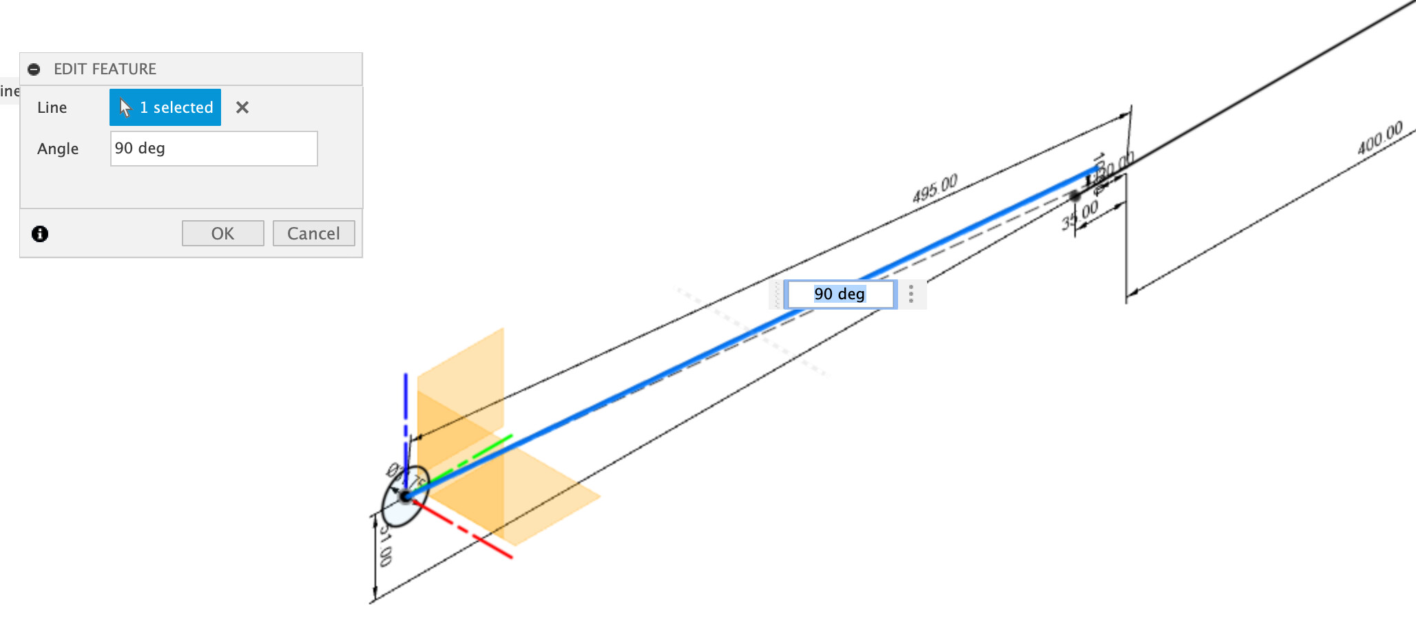
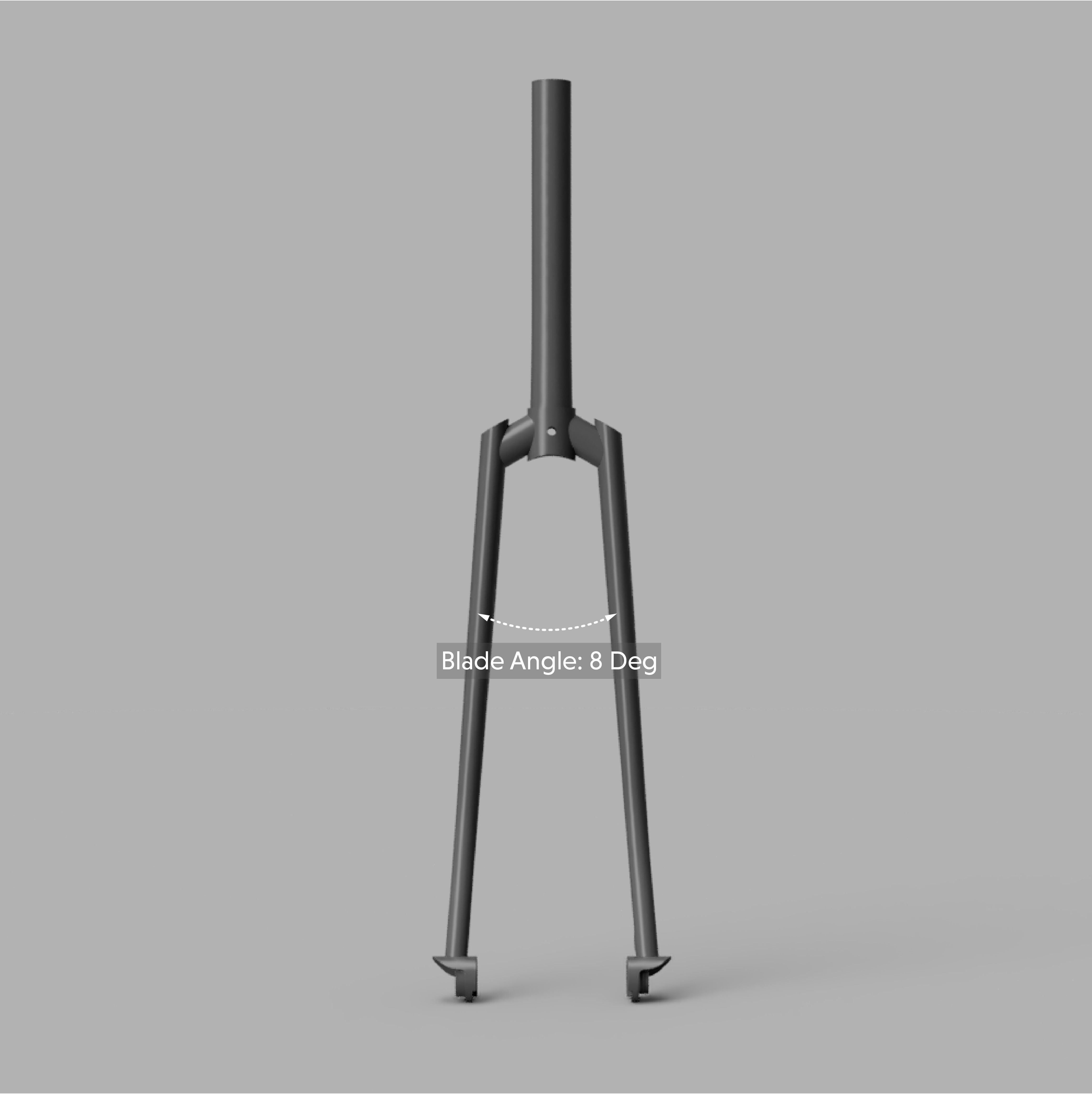
That fork was designed such that the segment is centered on the steerer where it is mitered. If the segment was 90° instead of 108° (as drawn), the 2.1° angle magically disappears.
Coming in here late with a question: How do you get the segments to intersect the steer tube and the fork legs at the centerlines of each? I’ve tried it a handful of ways, but seem to be missing something each time. Thanks!
disclaimer There is probably and easier/more better way to do this.
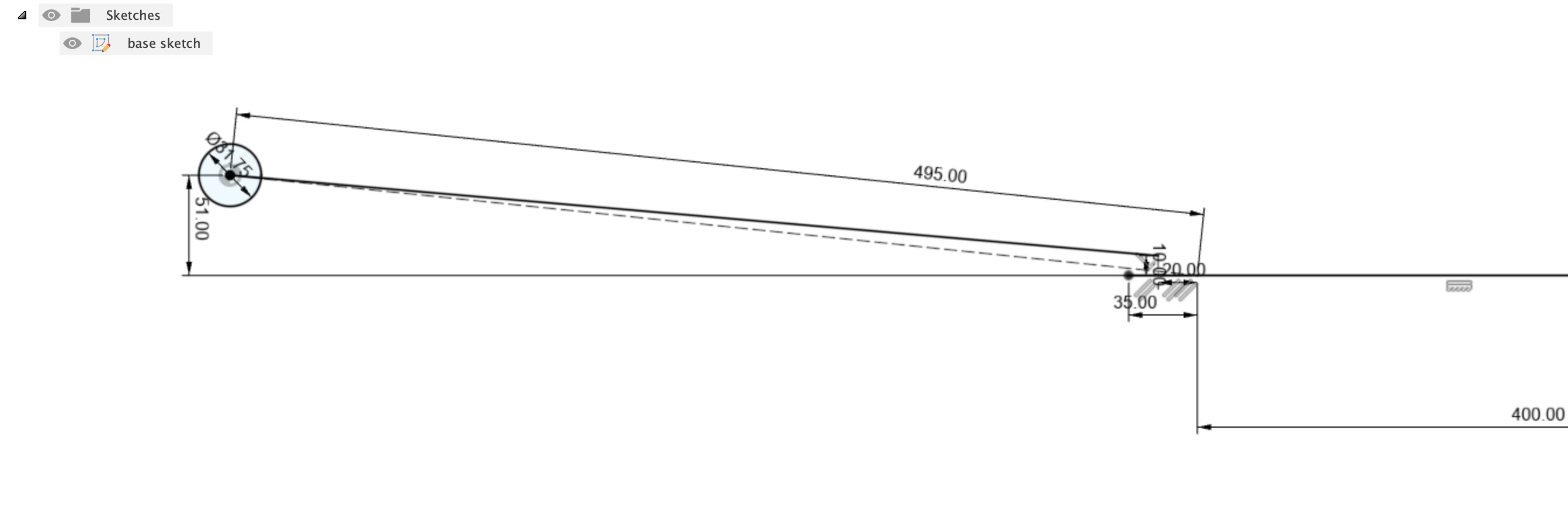
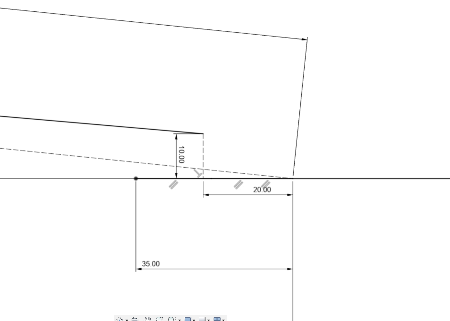
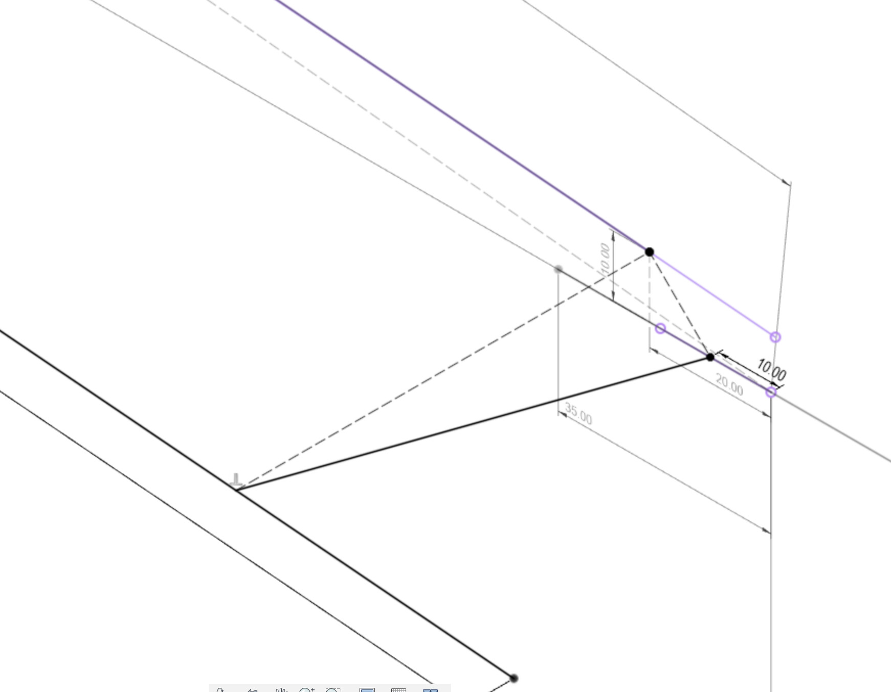
Here’s my base sketch showing profile view of the fork. The 10mm is an offset for leg centerline to steerer centerline
poopie’s breakdown is great. I think the key step is the 3D sketch. 3D sketches are often sketchy (get it?) but they work.
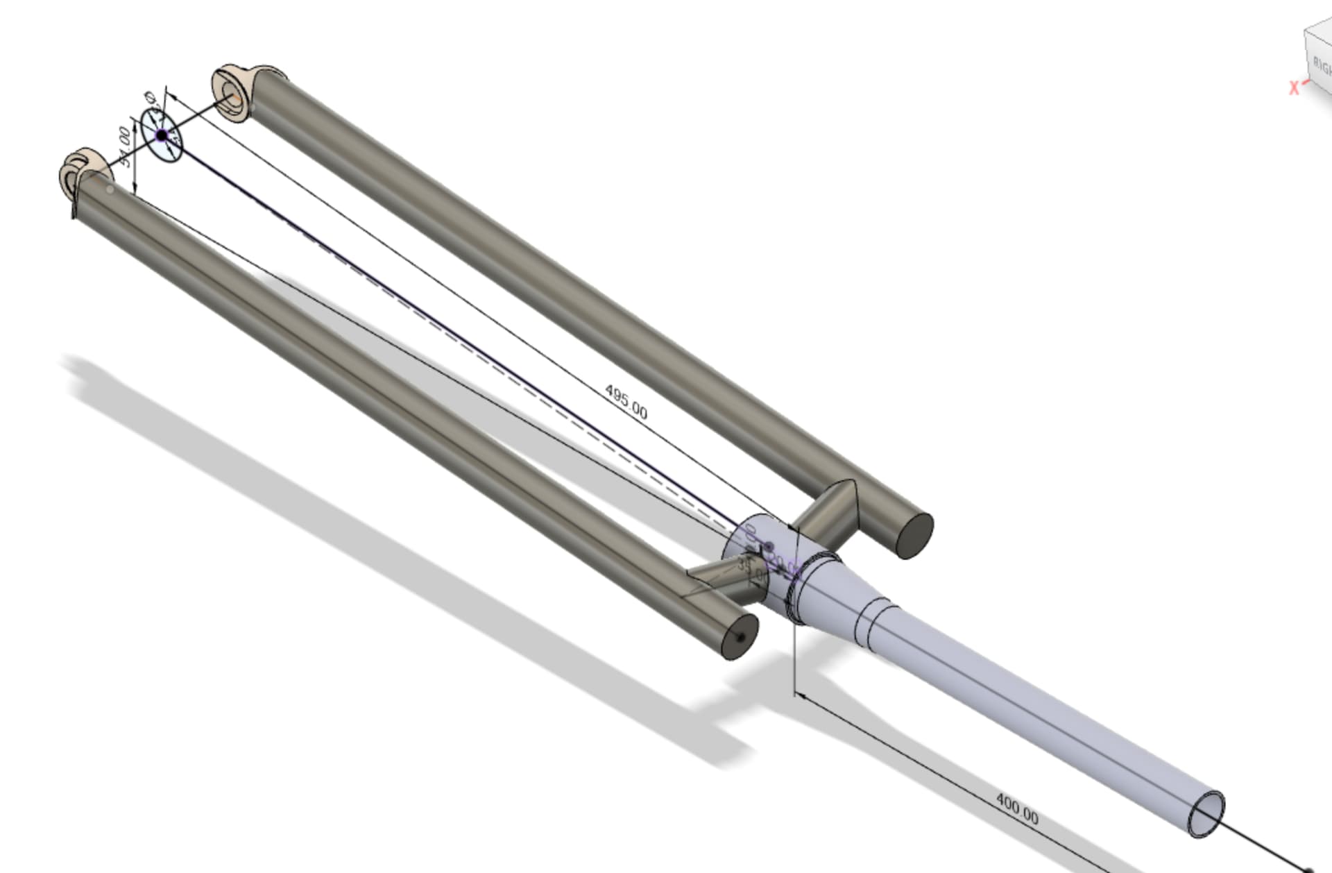
The fork that I CADed up is less complicated (the fork legs are not offset forwards), so I didn’t need a 3D sketch. You can download my design and reverse engineer it: https://a360.co/4077Wmr
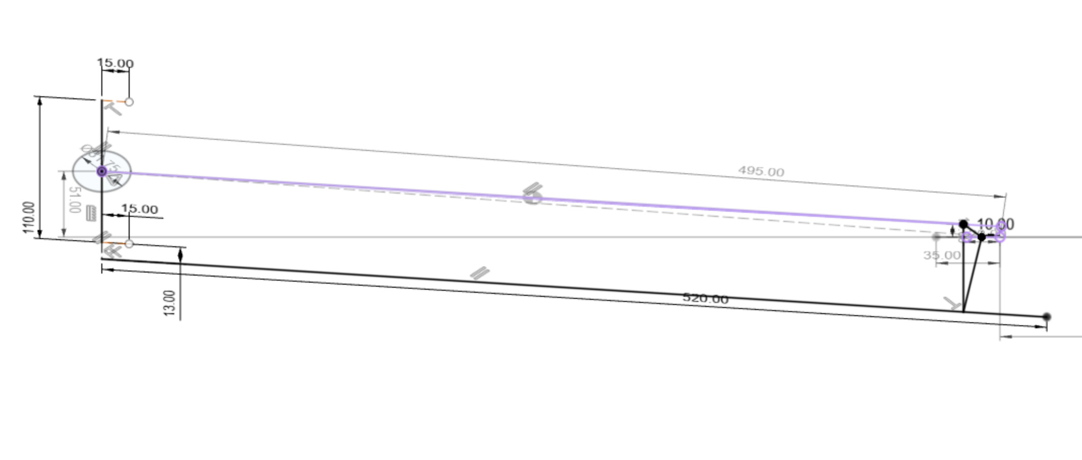
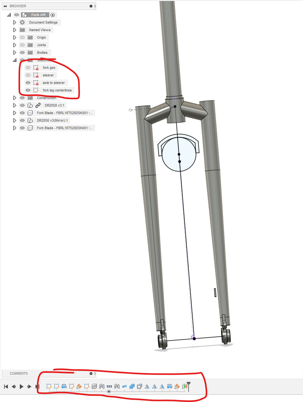
I named the sketches. Between that and reverse engineering the history bar at the bottom, you can get figure out how I did it.:
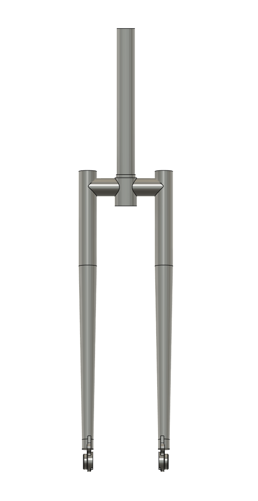
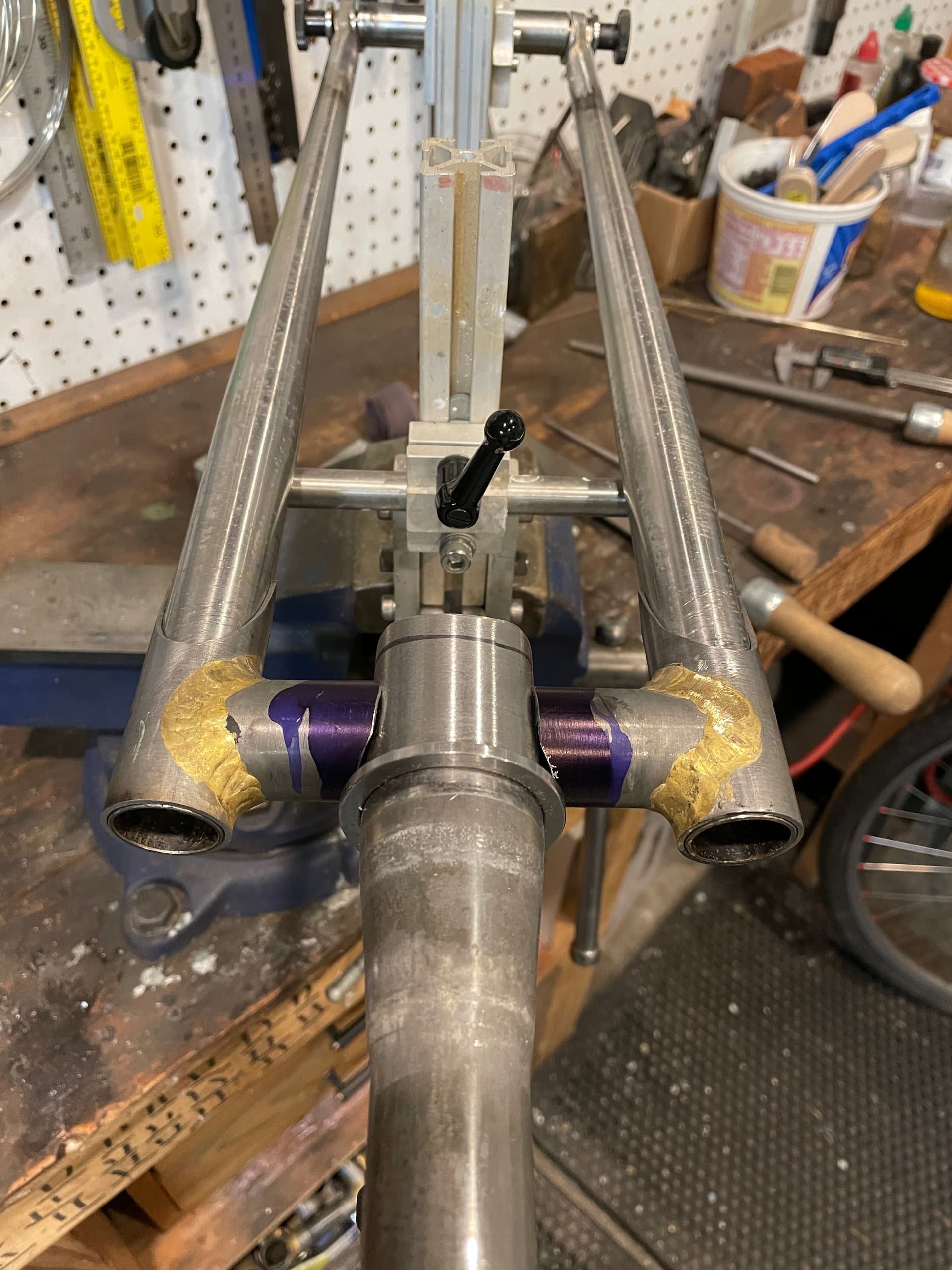
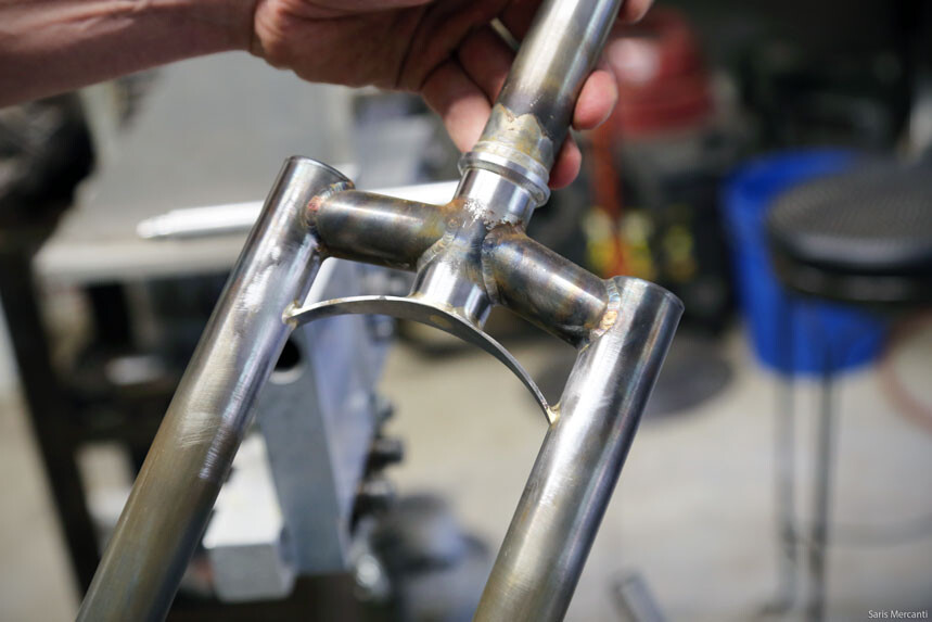
This fork is still being created (this was the first fit up of the miters -the width and angle still need adjustment!) but it will be similar to what @Meriwether posted above. The blades are 1" round blades. The crown is made from 1.125 x .065 tubing internally turned to the correct ID for the blades. They will get silver brazed - hopefully this weekend. Future versions will have angled segments to provide better clearance at the DT while also providing clearance at the tire.
I know this is an old thread, but I would appreciate some clarity on:
“-With my fork blades (about 65mm of thick section at the top) please please please don’t get fancy and attach extra stuff to the bottom of the fork crown below the butts. This is a recipe for a broken fork.”
Walt is not in this forum any longer, but it seems to me that’s exactly what he was saying. The non-butted section of tube is .8mm, and that’s probably too thin to be attaching an arch.
I was getting nervous all my visions of fancy extra stuff would need to be scrapped in general. It seems like this advise an important consideration when choosing materials.
If ya into fancy extra stuff then maybe sleeving the upper section of the blades will provide the thickness you need to add an arch. That might up very busy looking though. There’s a MTBR article discussing this that’s worth a read either way.
Not really sure what I want to do in the end,but more trying to understand the constraints at the moment. But I do like the arch look,and those sleeves are cool too…
Thanks for that link,that is a very interesting discussion. I will be referring back to that again I’m sure.
On the fork I built with Walt’s tubes there is a lot of flex. It is a long fork designed to swap with a 29er 120mm travel fork. Seeing the fork tubes flexing so freely much highlights in my mind that I would not want any potential stress raisers attached below the start of the butt taper.
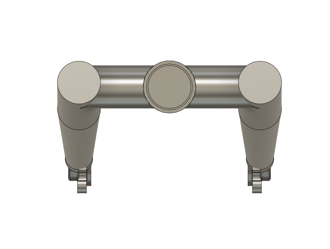
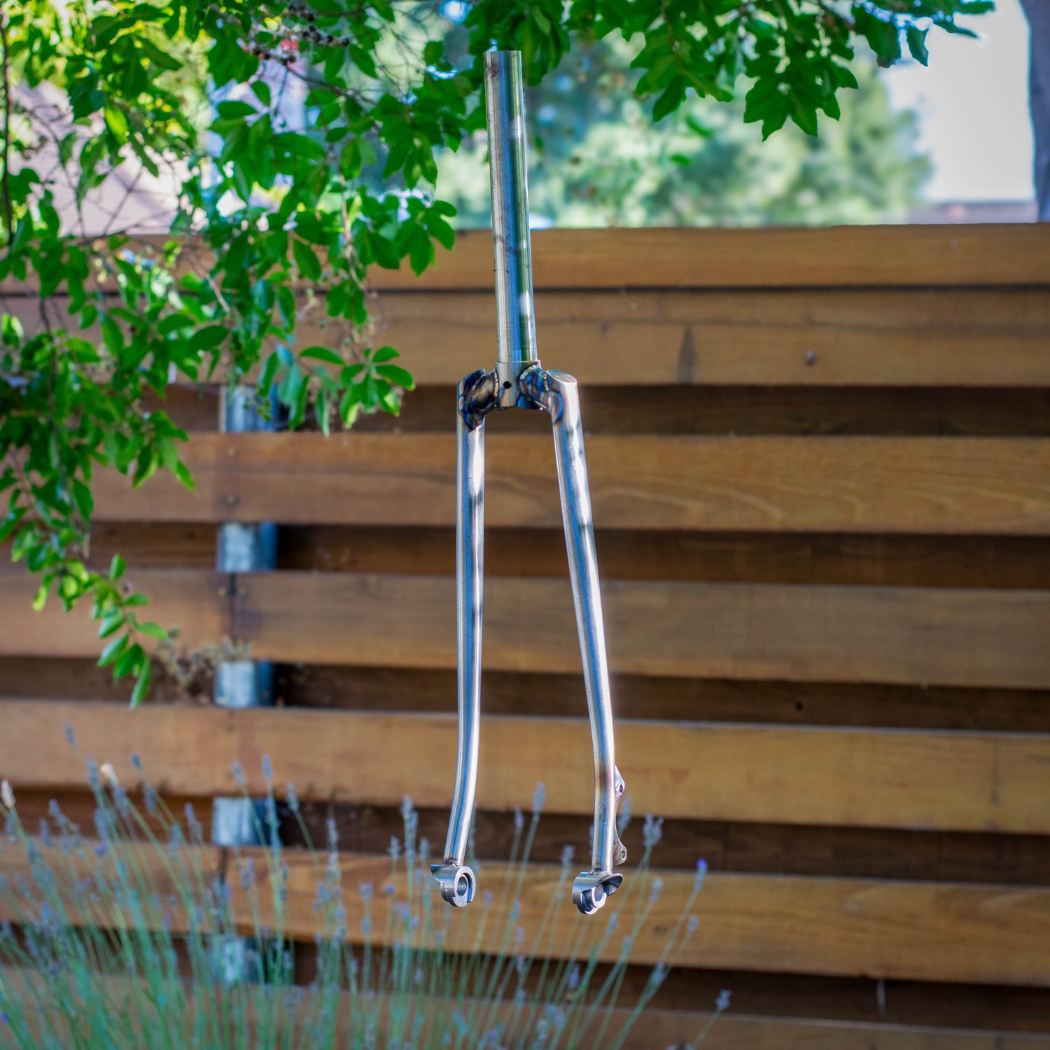
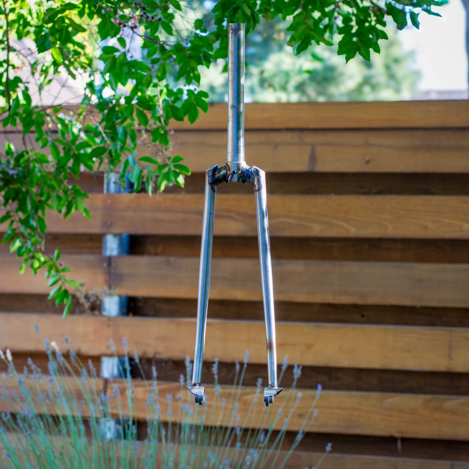
Here’s a segmented fork I made with raked fork blades. I used 1" OD x .049" wall tubes to connect the blades and steerer (which is a Paragon MS2026 straight steerer).
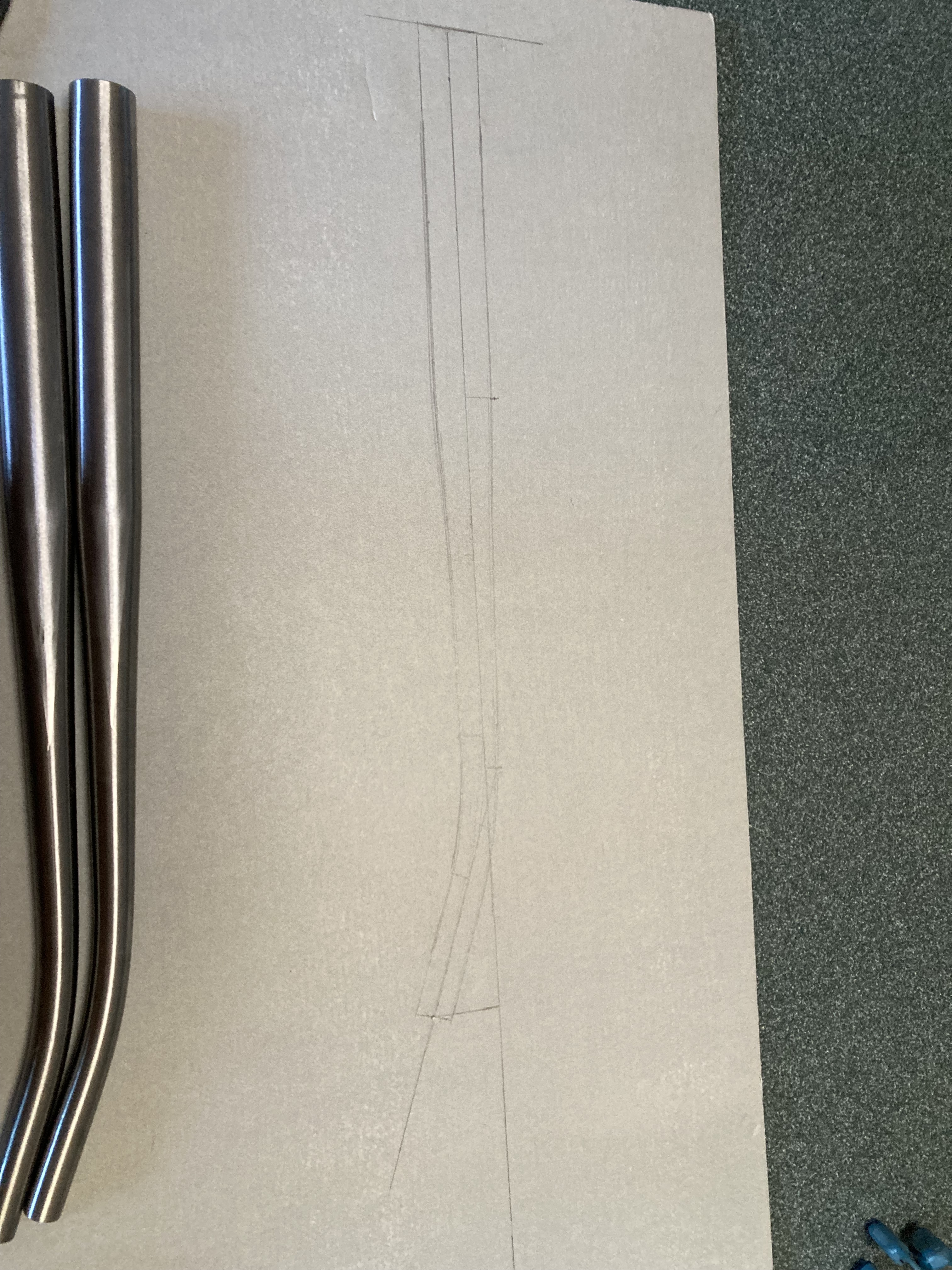
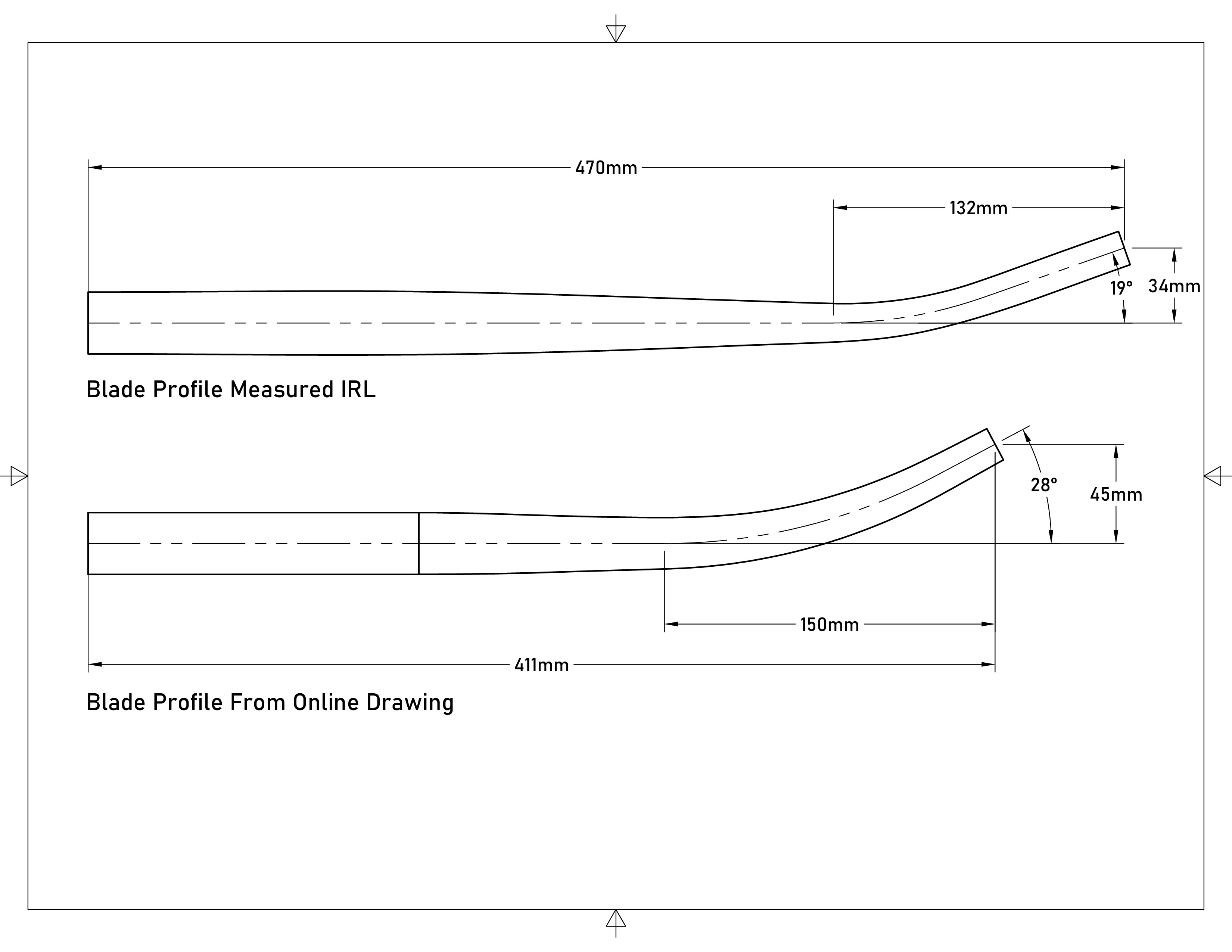
Measure Fork Blades: The blades I received were significantly different (length, rake, taper, etc.) than the drawing provided by the manufacturer. I ended up “projecting” my fork blade onto a large piece of paper to determine the blade profile.
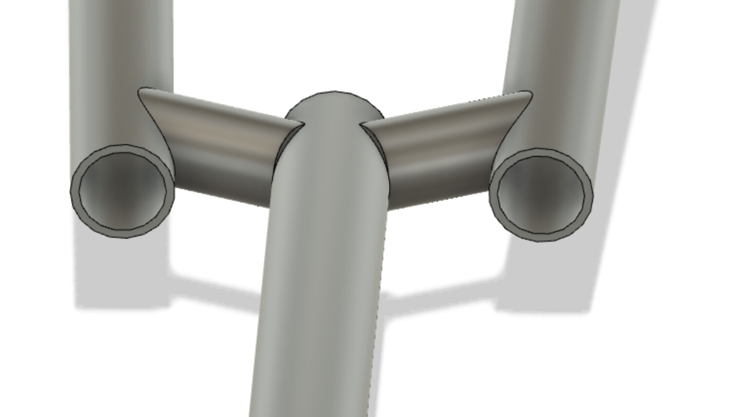
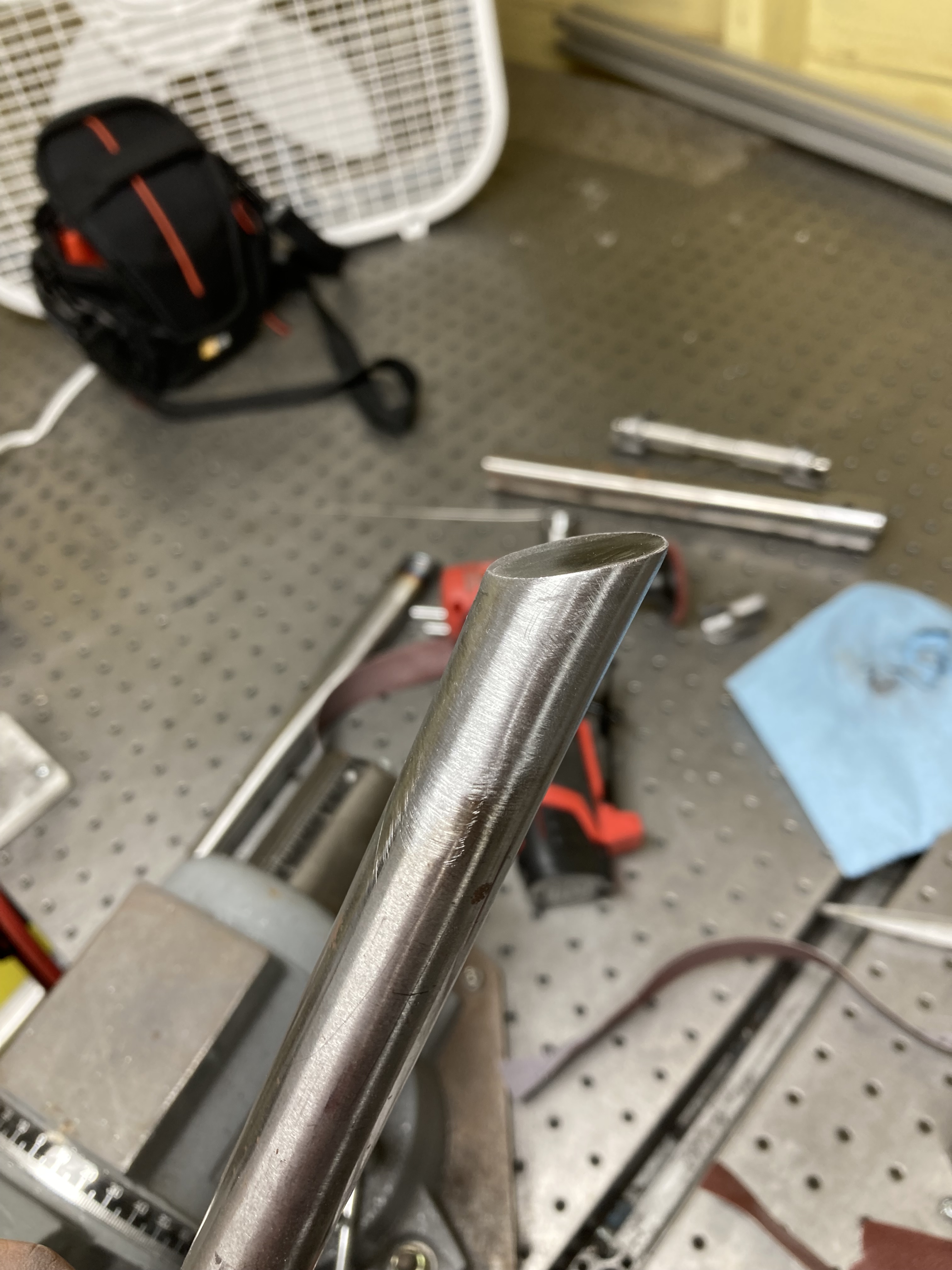
Miter Fork Blades, Bridge, Steerer: I mitered the blades (including adding an angle on the top side of the blade) on the mill.
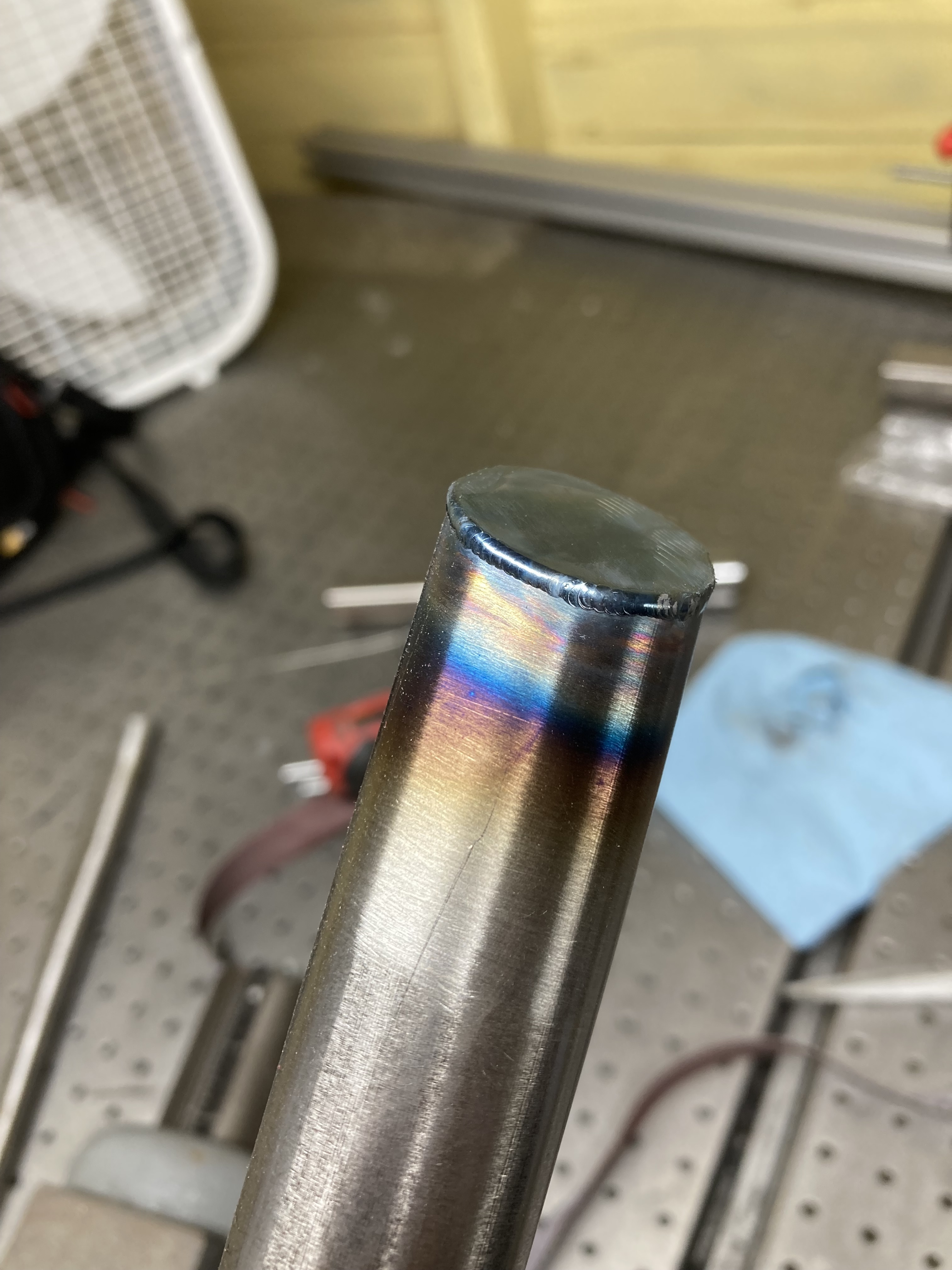
Cap Fork Blades: I welded some small 16 Ga. caps onto the top of the blades and then used a combination of sanding and die grinding to smooth the bead.
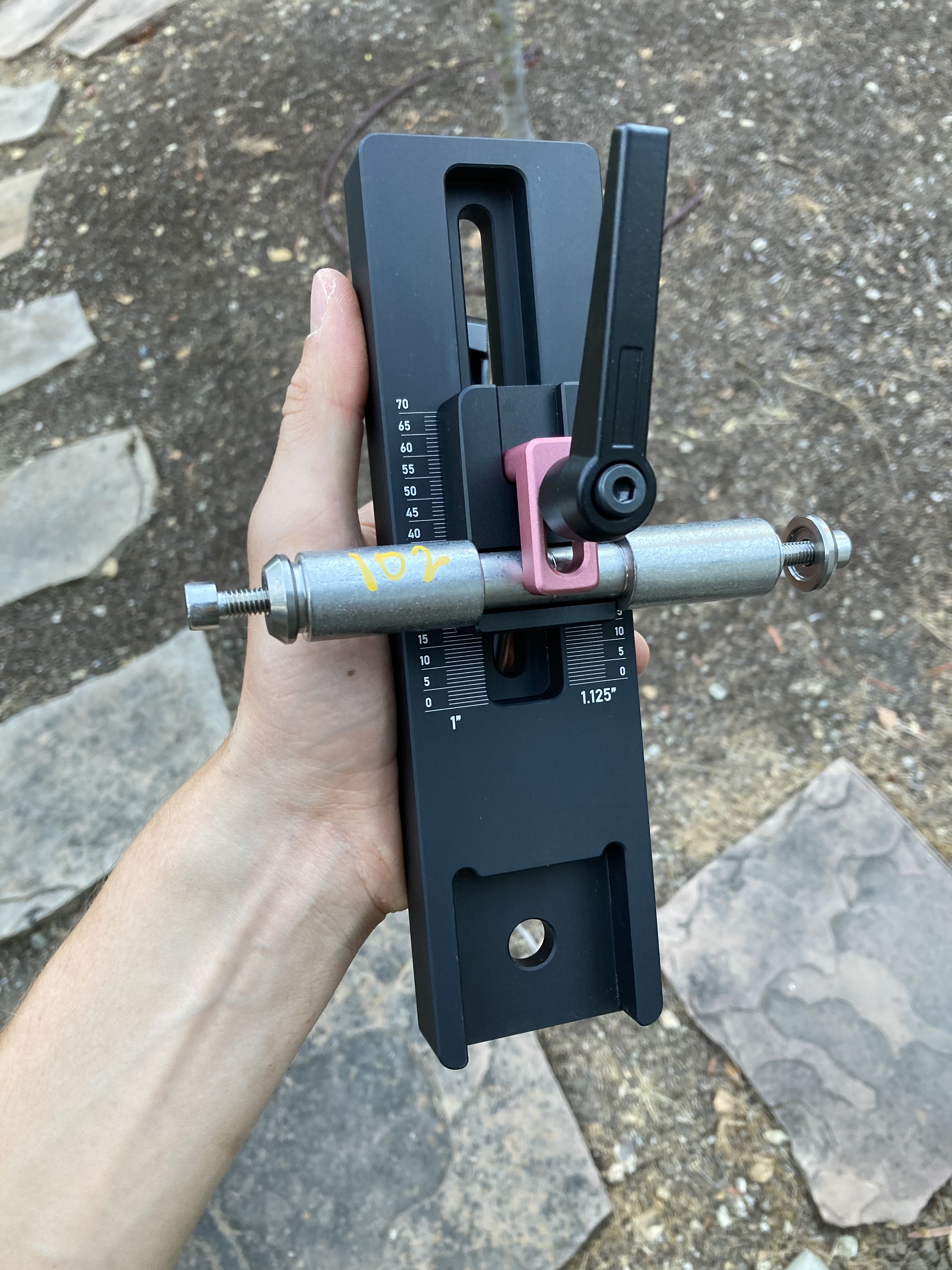
Weld Fork: I welded the fork using an extrusion fixture based on 4545 profile. I used JLCPCB’s CNC service to create the fixture components (picture of the axle tower attached!) The price, quality, and speed of their service is impressive.
Thanks! I paid $101 for the 3-part axle tower (including machining, ANO, and fiber laser marking). I spent $86 on the steerer holder, so the entire fixture was around $187.
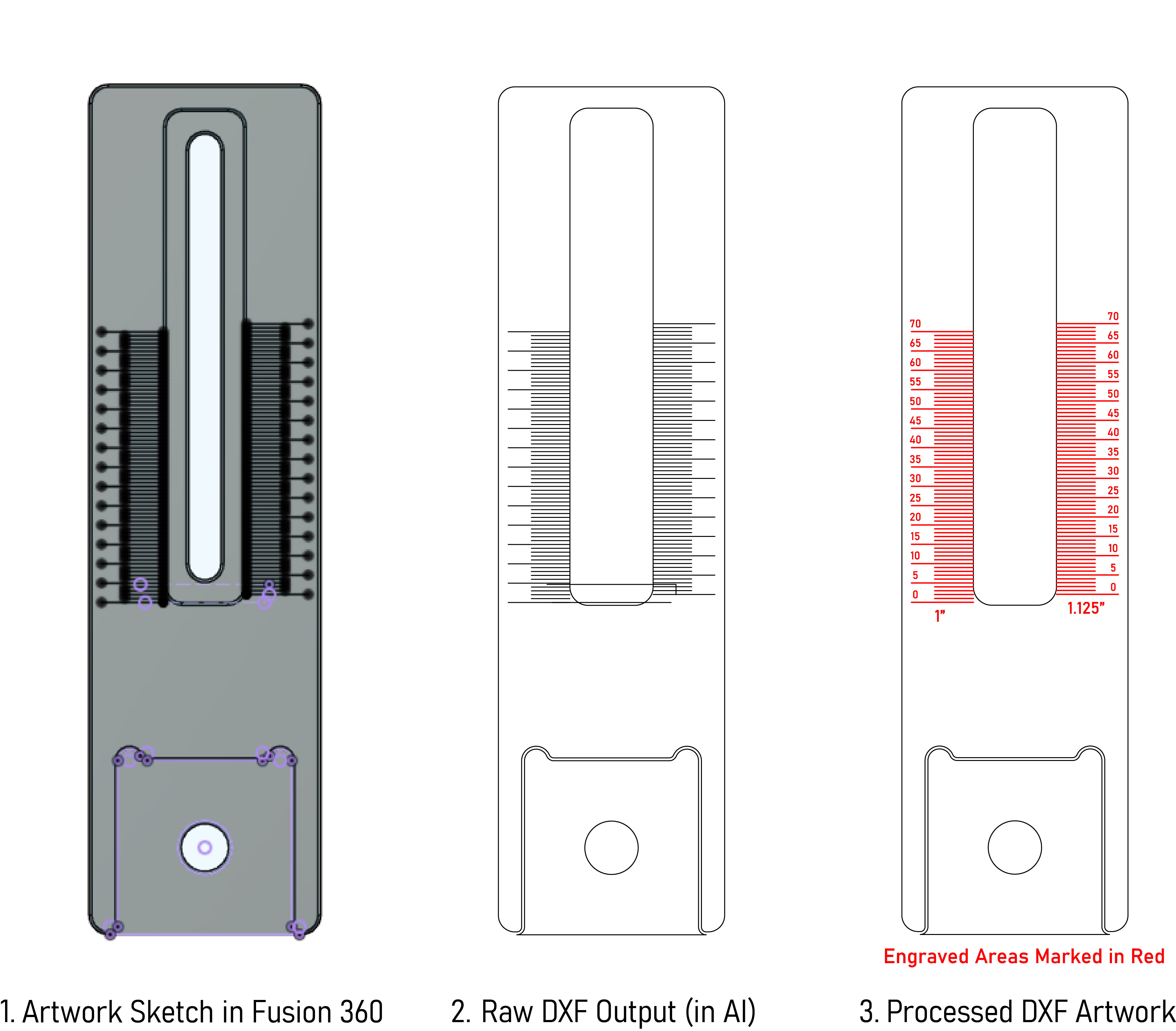
Thanks, Daniel! I created a basic sketch in Fusion 360 with the lines and then used Adobe Illustrator to tidy everything up, change line colors, and add text. I’ve attached an image showing the overall process. I exported the processed artwork as a .dxf and uploaded it as a supplementary file to JLCPCB (you have the option to upload a file when you select laser marking on the surface finish tab).