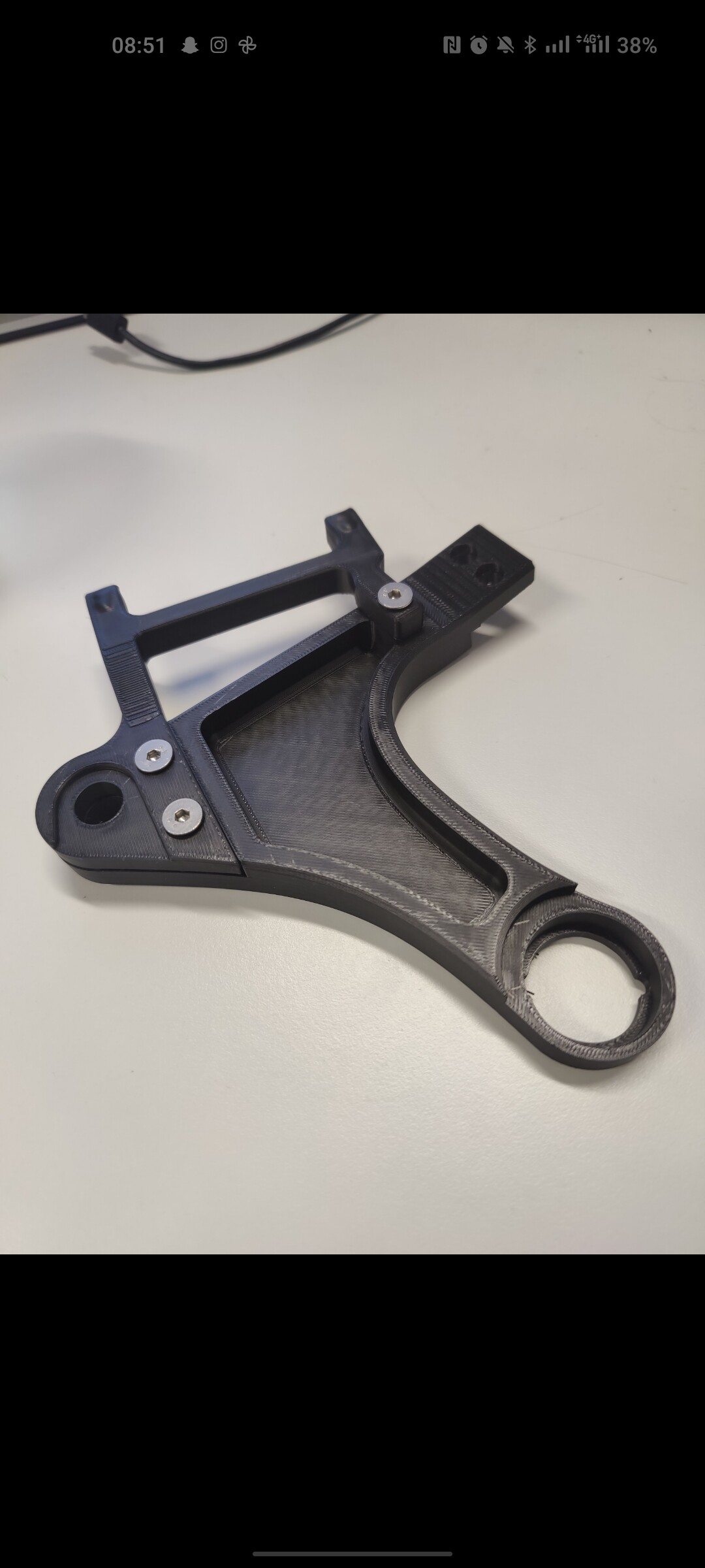
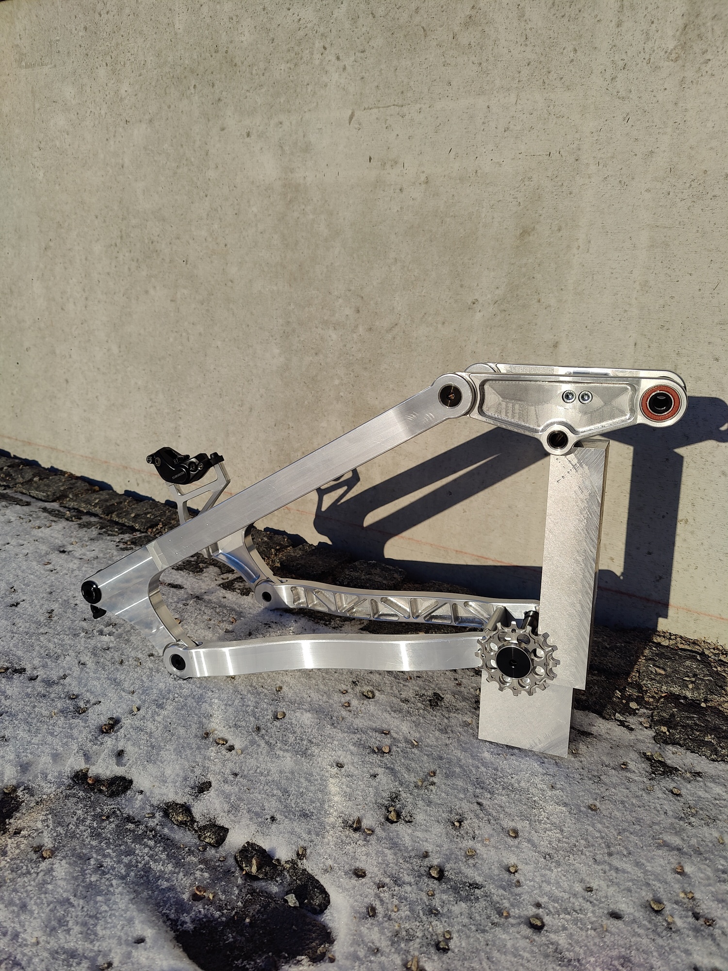
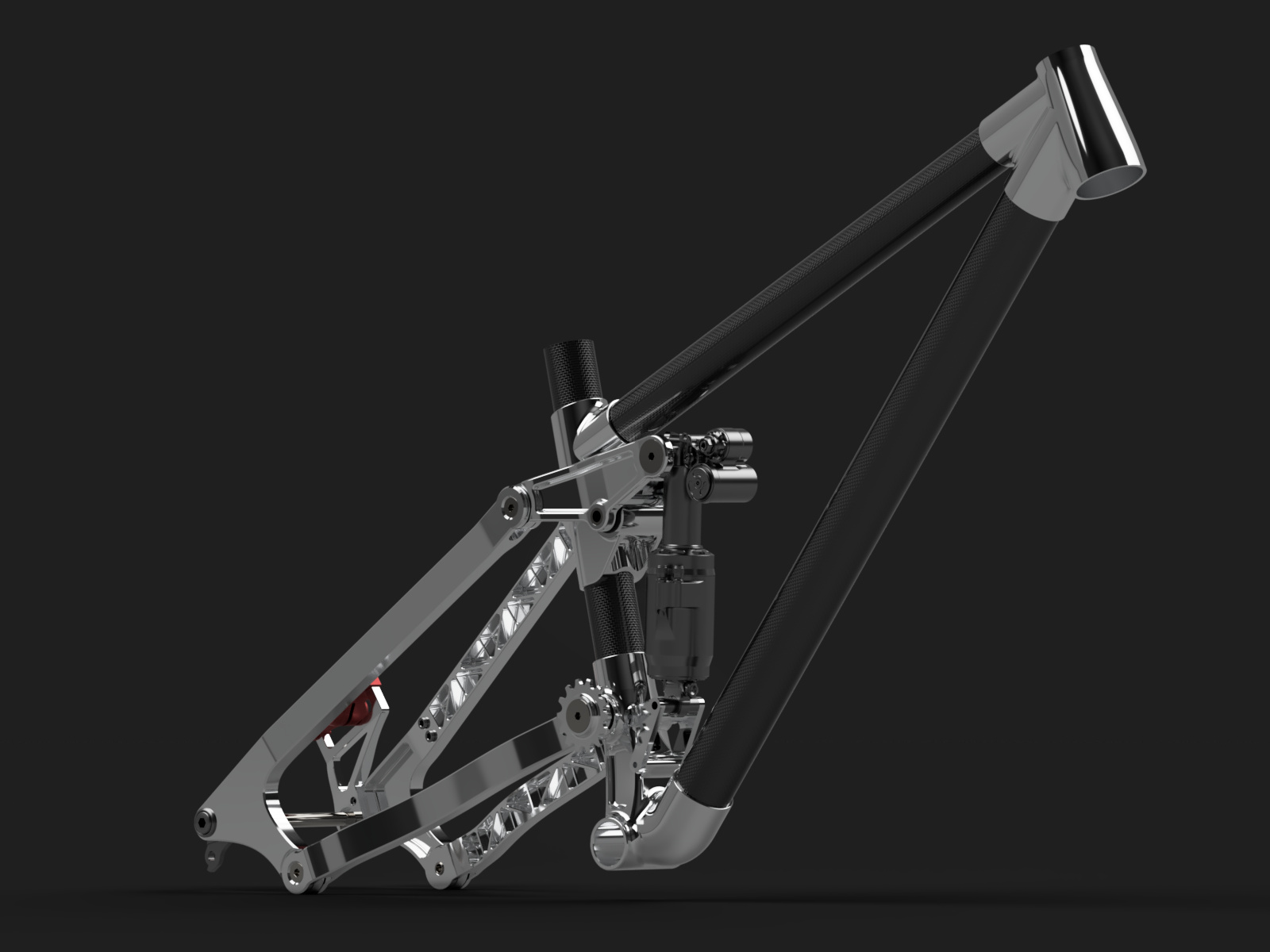
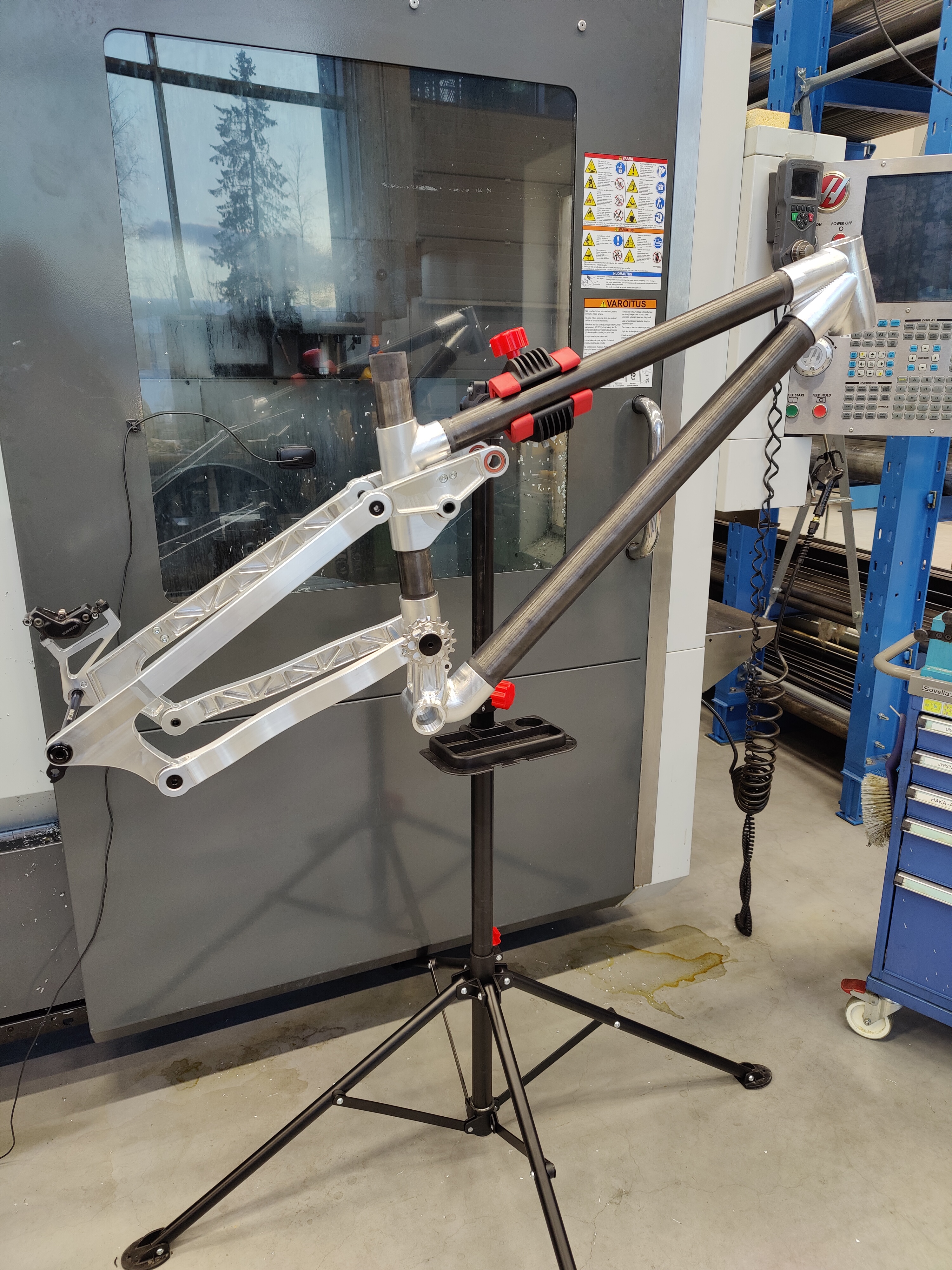
Yeah the vibrations are a bit of a concern with that design. I will be doing testing with that but I have another version ready where the brake mount connects to the dropout also from the upper part.
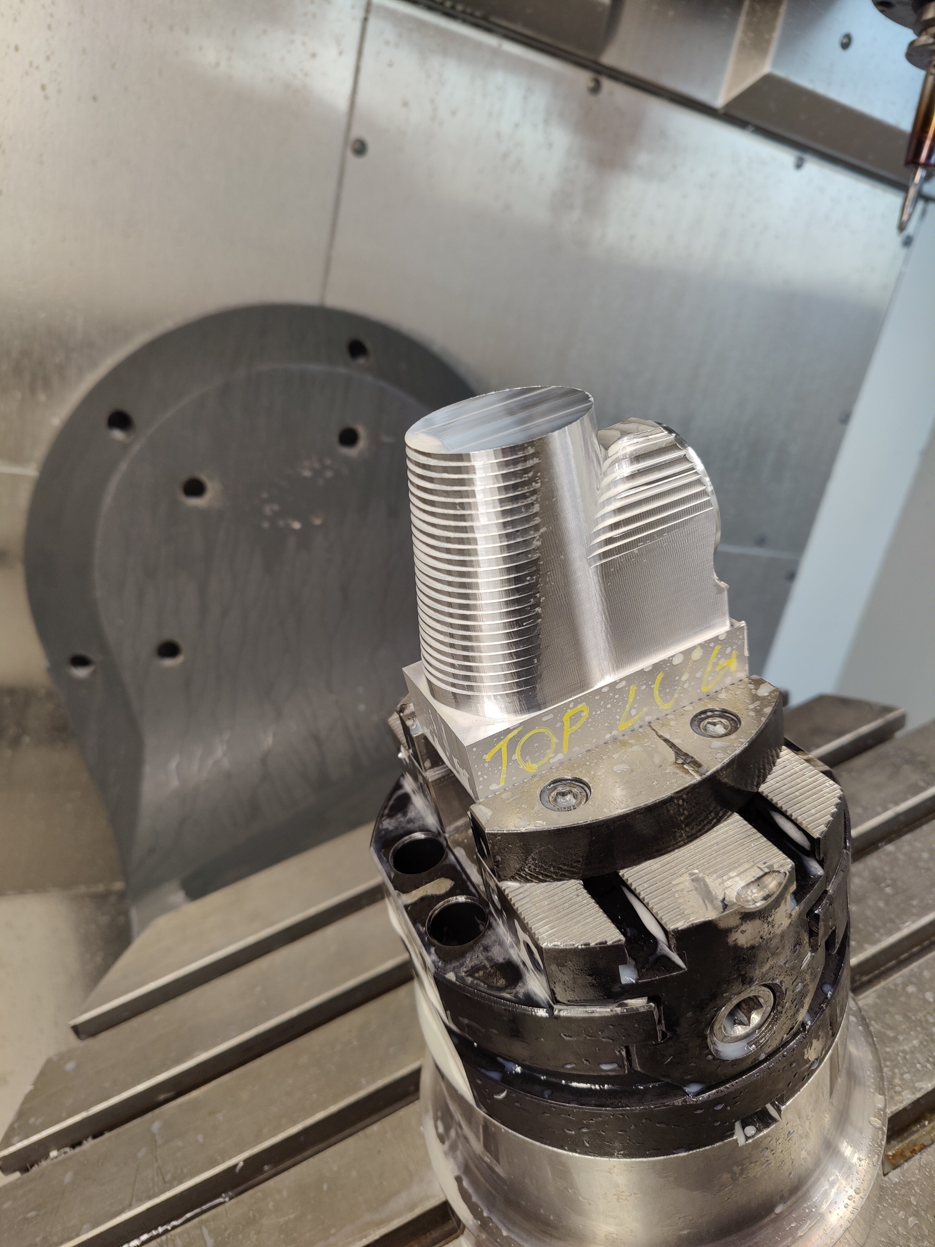
Short update. Some problems with the lugs as expected but 2/4 now made. Also starting to run out of time since I will be graduating at the end of this month
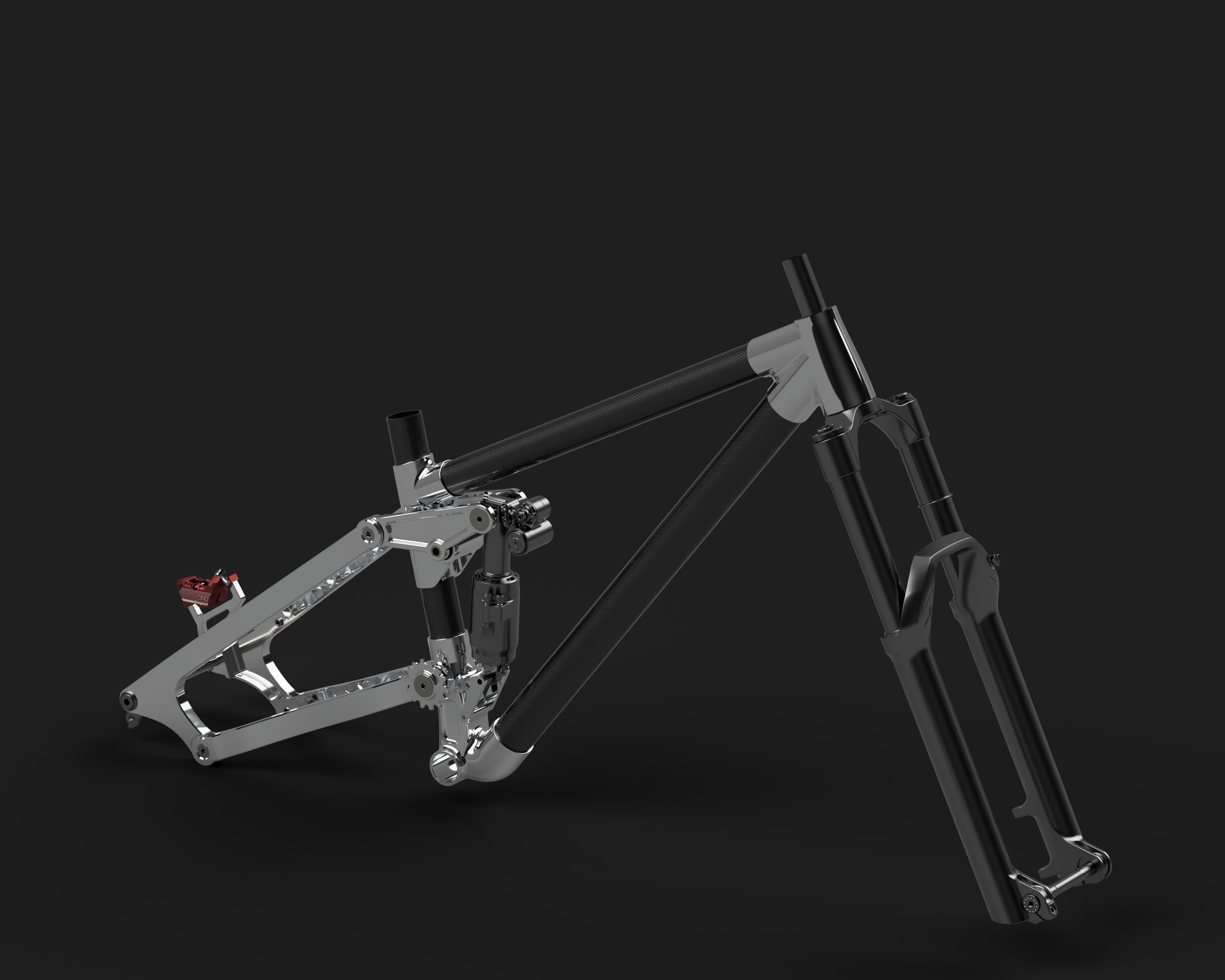
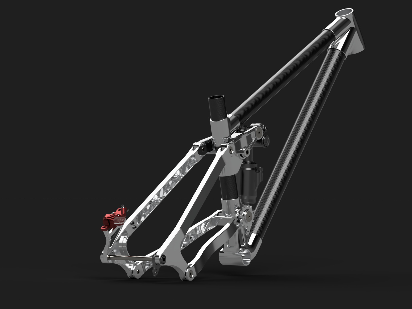
Custom tubes made to spec from carbontubes.eu / caas.si
Damjan was really helpful with all the layup stuff etc. They were around 50-80 euros per meter so not as expensive as I thought.
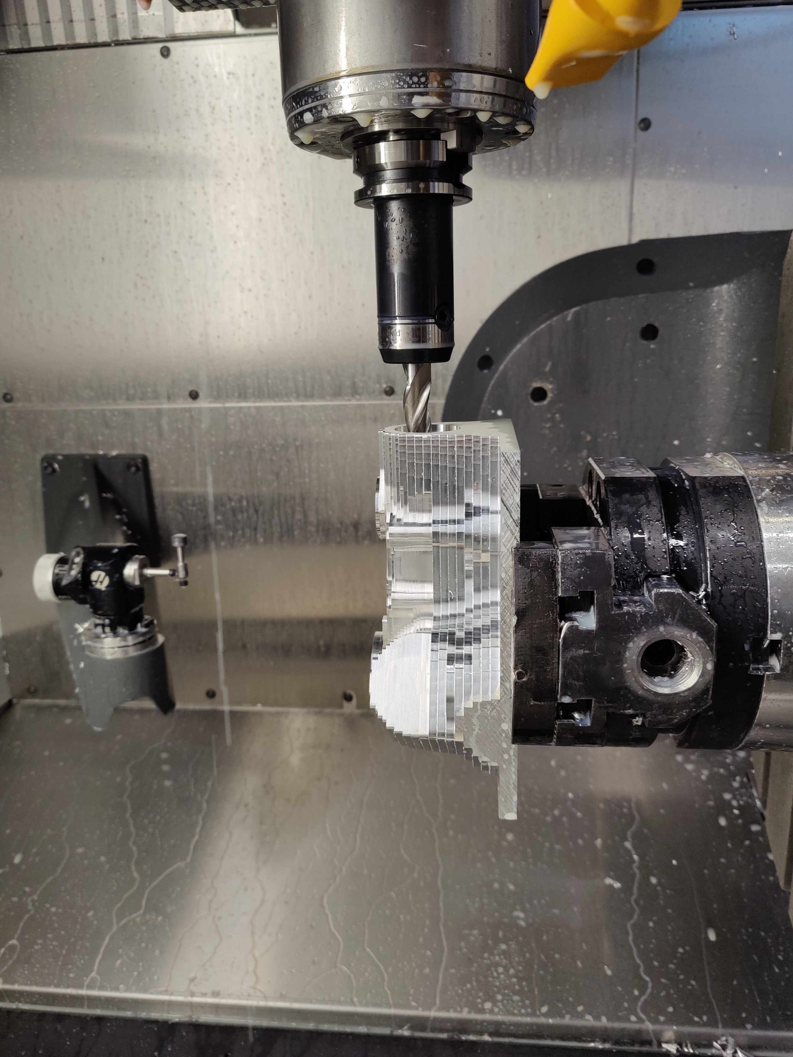
This is nice work! Did you have any issues indicating in the part with the 3dp soft jaws? What type of tooling did you use to reach in for the deep bores?
Cheers,
Pete
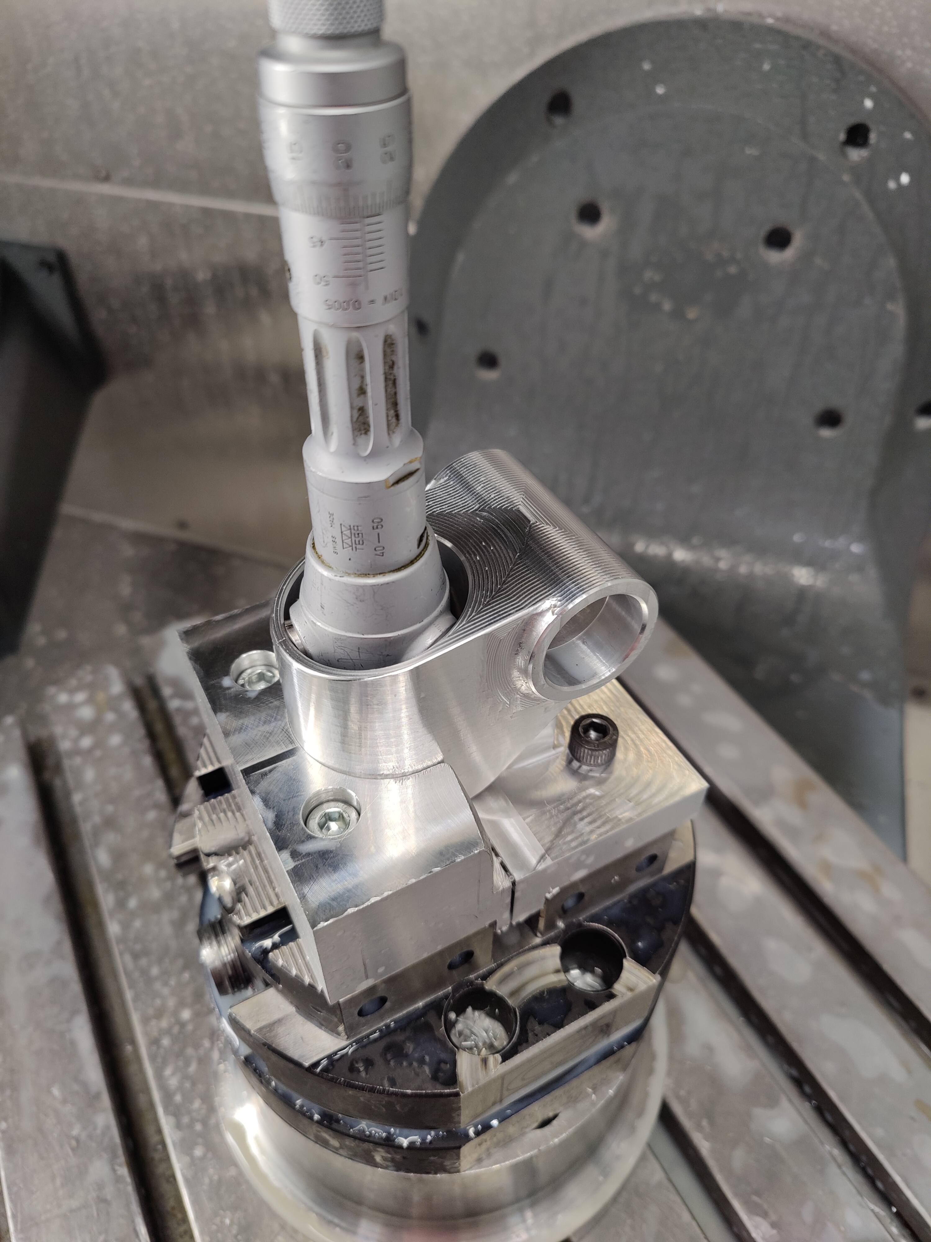
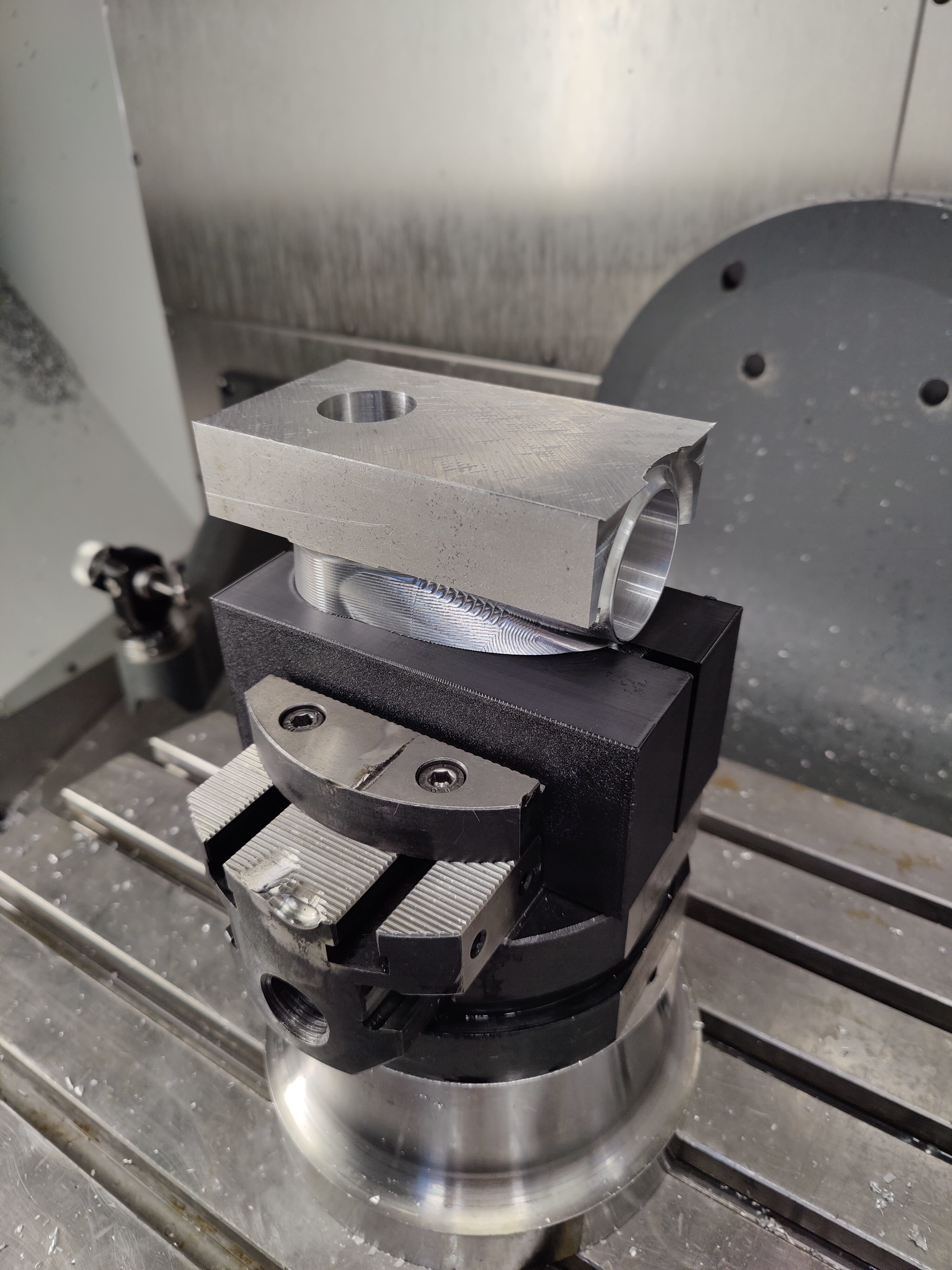
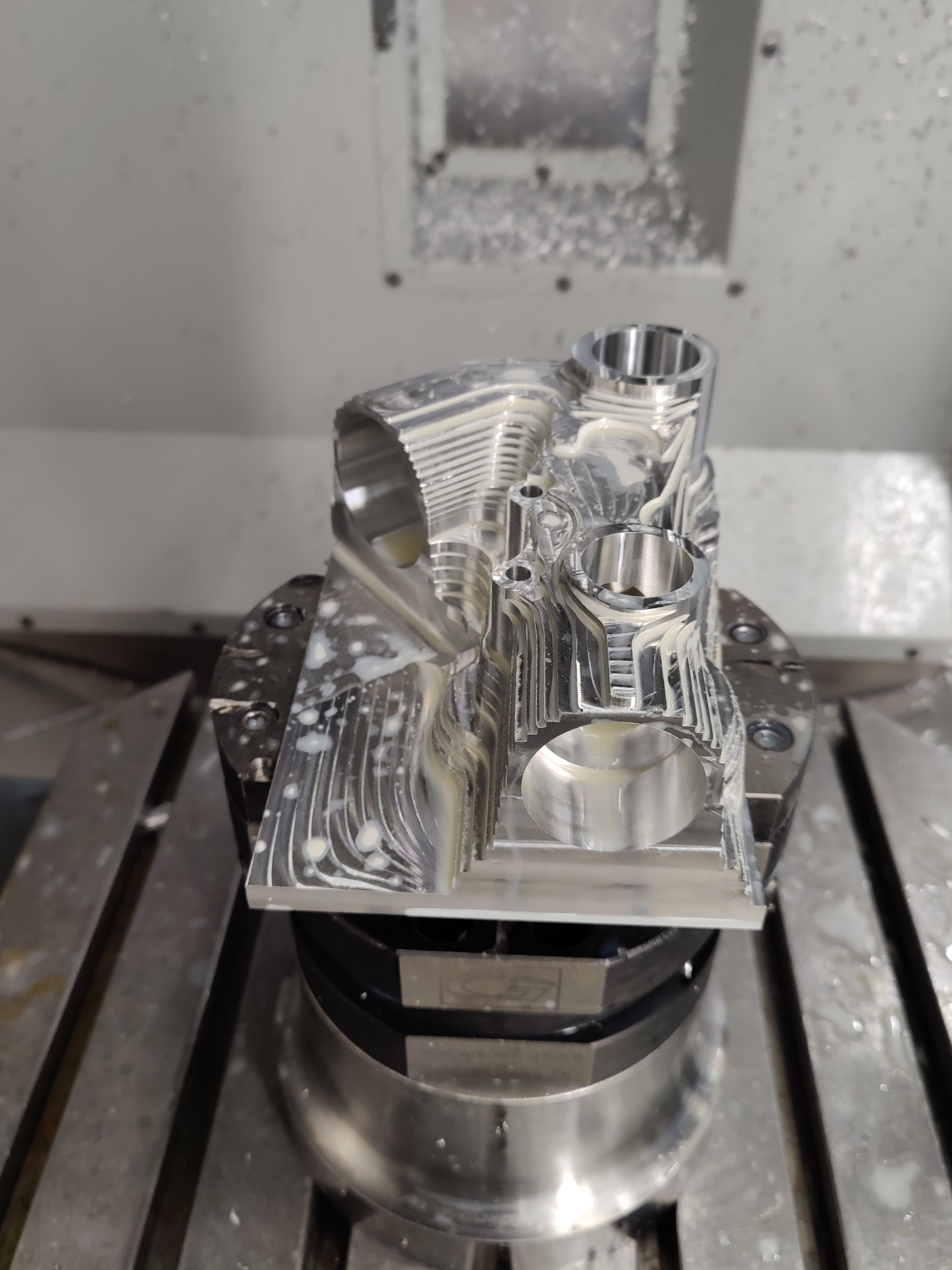
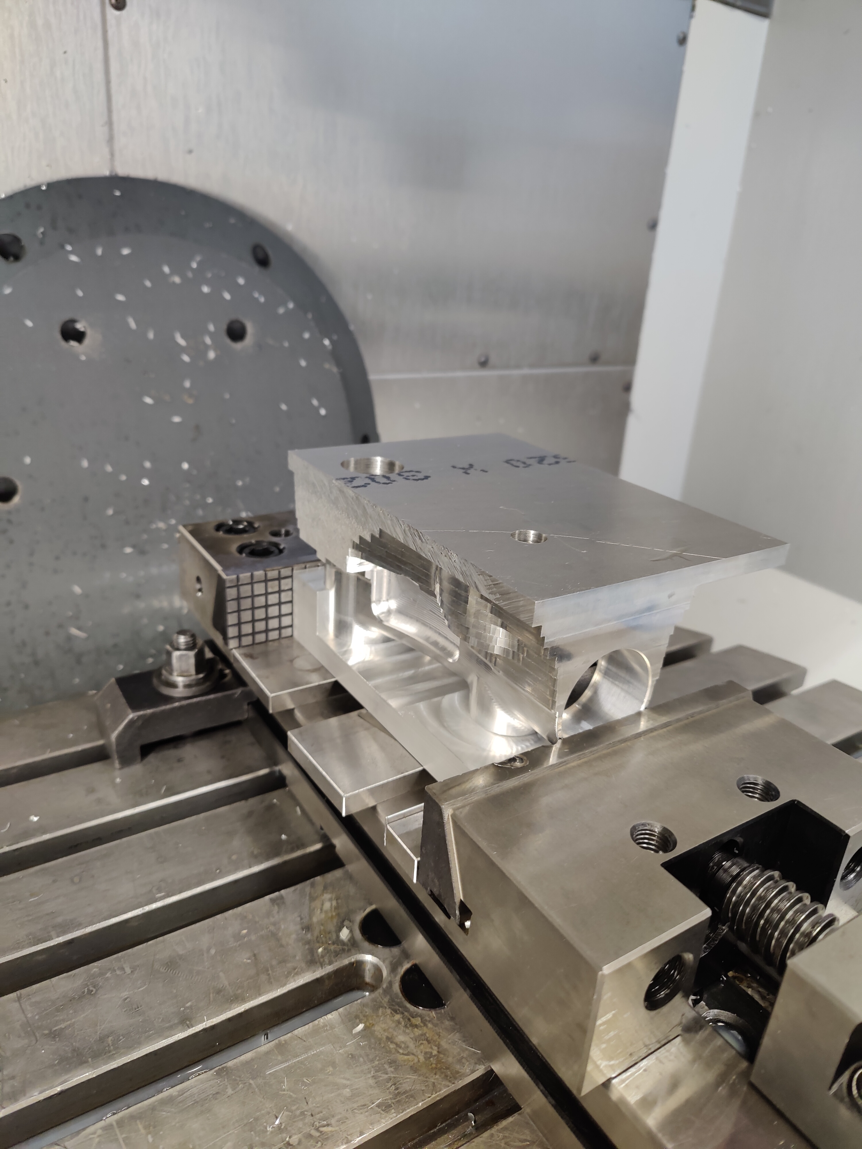
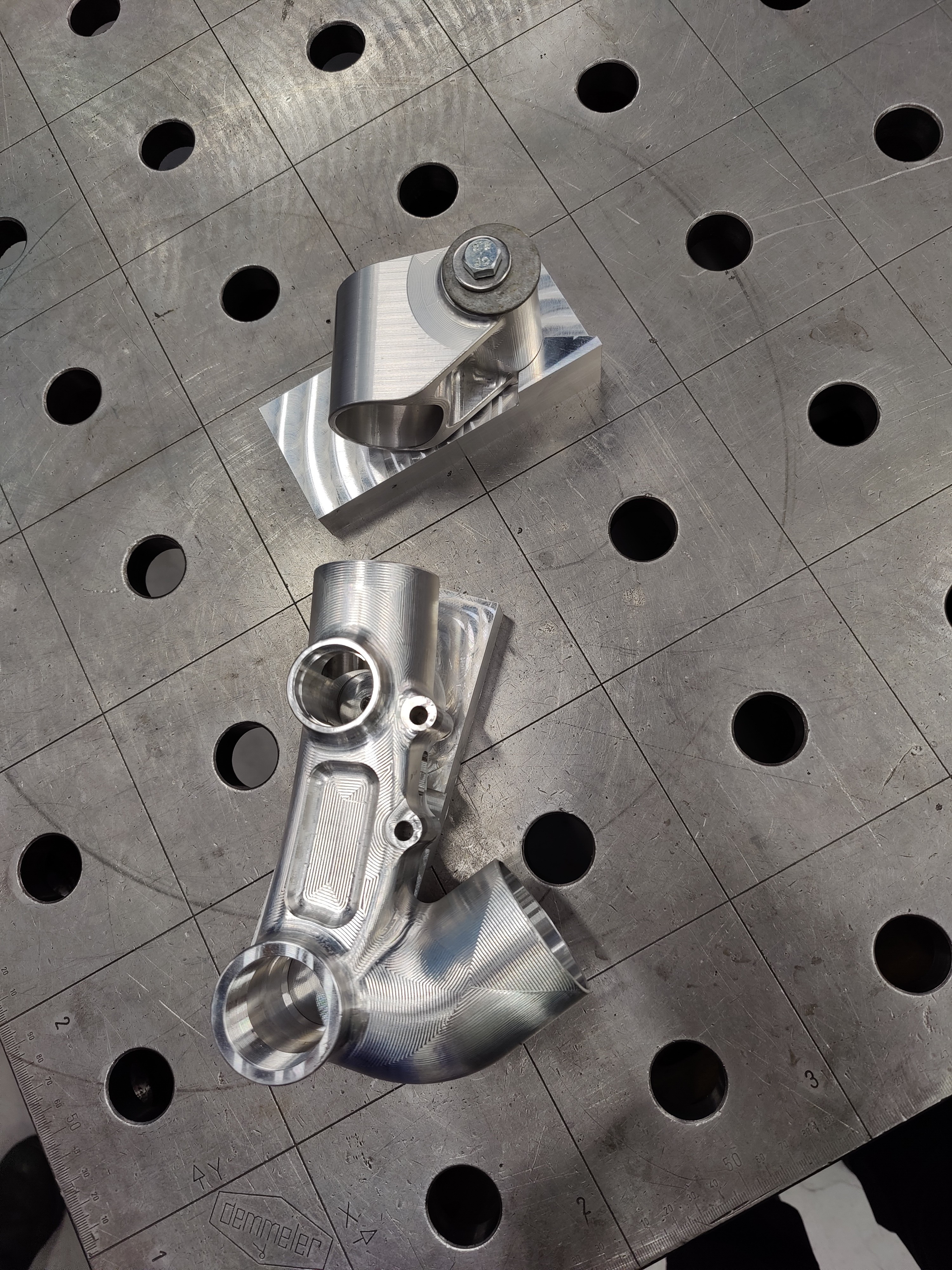
The soft jaws worked much better than expected. I was a bit worried how accurately I could locate the part but it turned out pretty good. I measured the Z from the bottom of the soft jaws where the headtube bottom is located and the XY from the bore made in the first op.
There was a lot of problems with the long tooling and using the tall vice that enables 5 axis machining since our machine wants to make the XY motion at the tool change level before moving +Z axis. And also some problems with the “safe” positions making moves over the part when the table is at home position. Because of that I couldn’t use all the tools and holders that was planned.
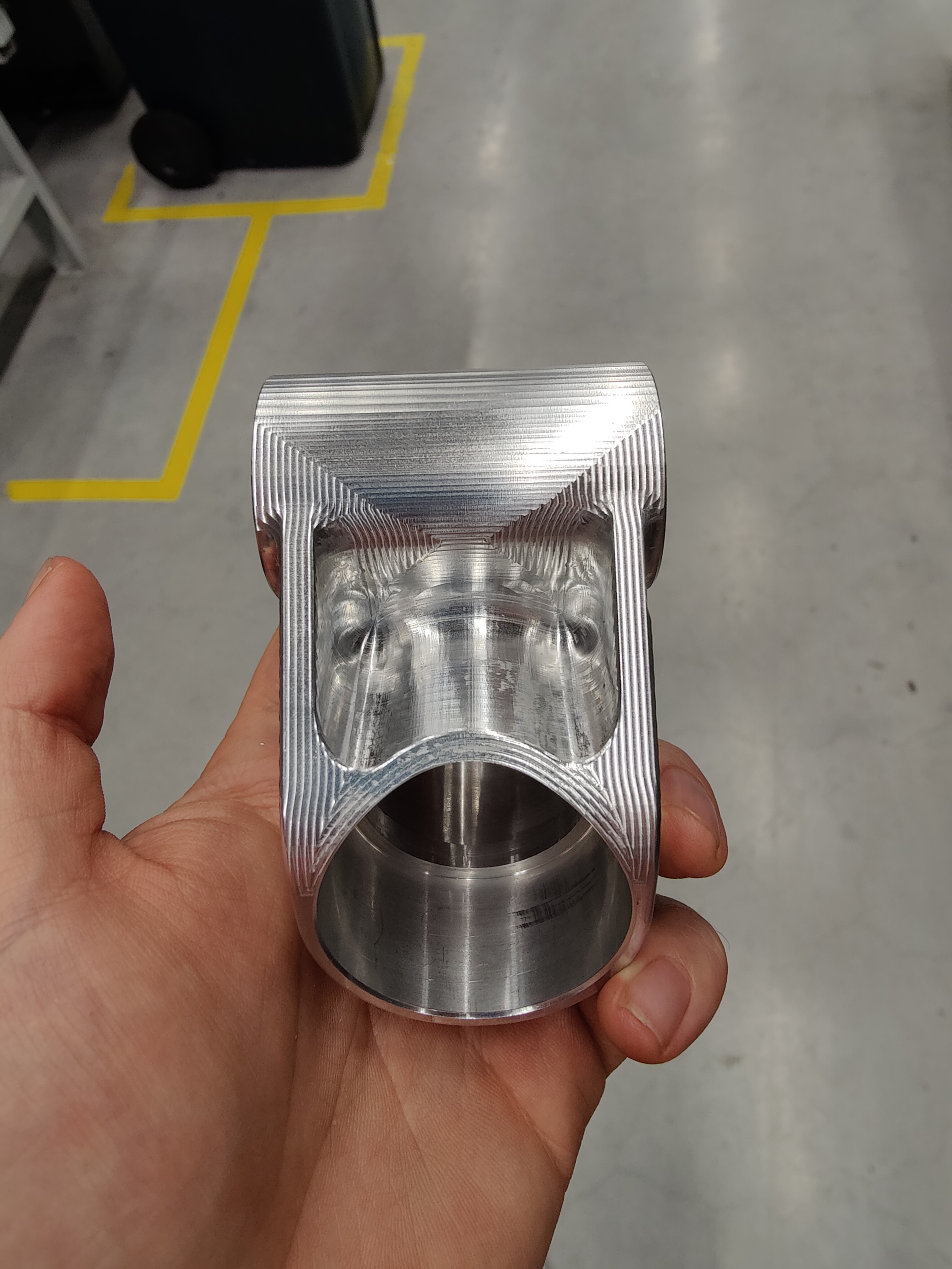
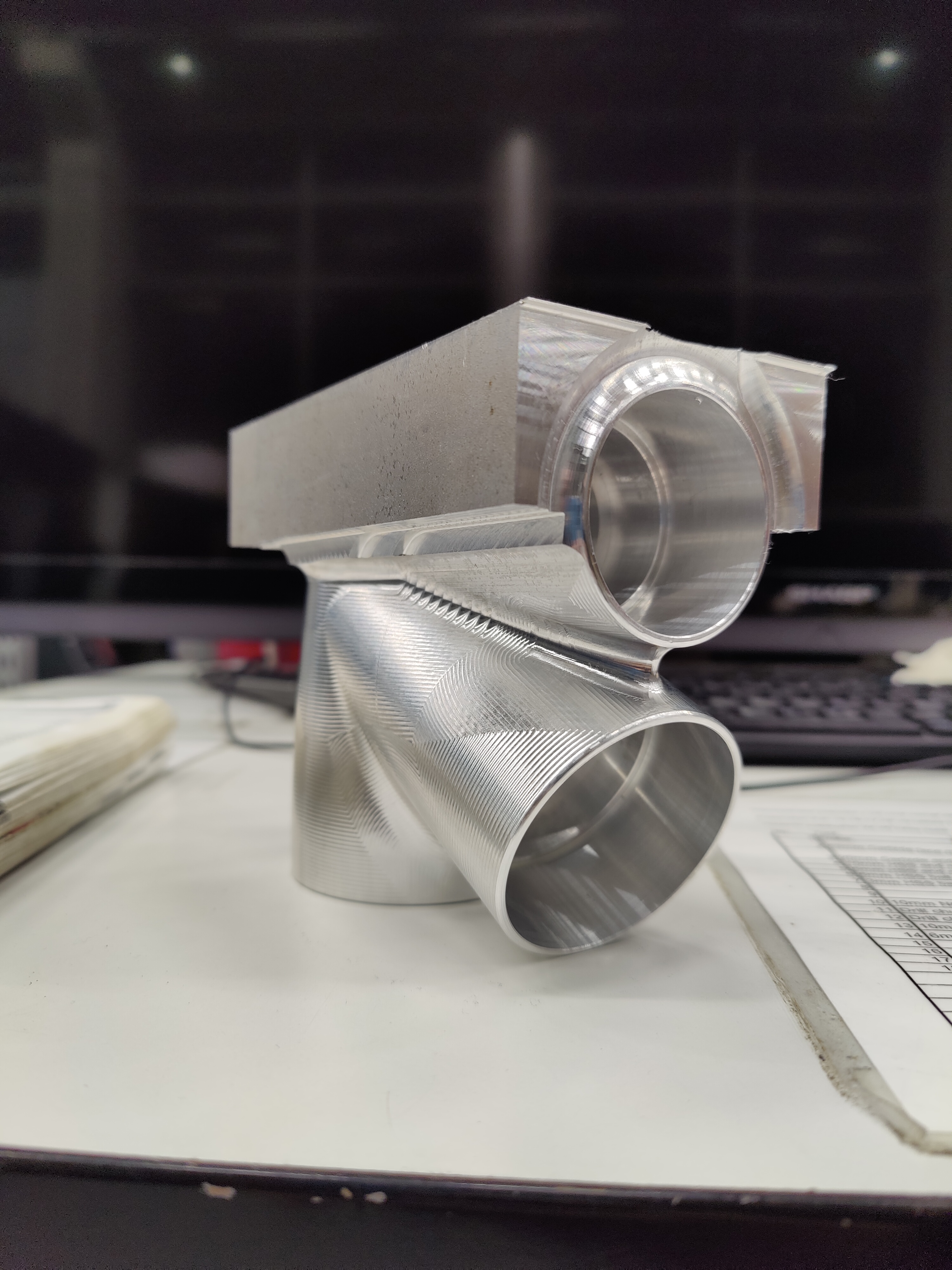
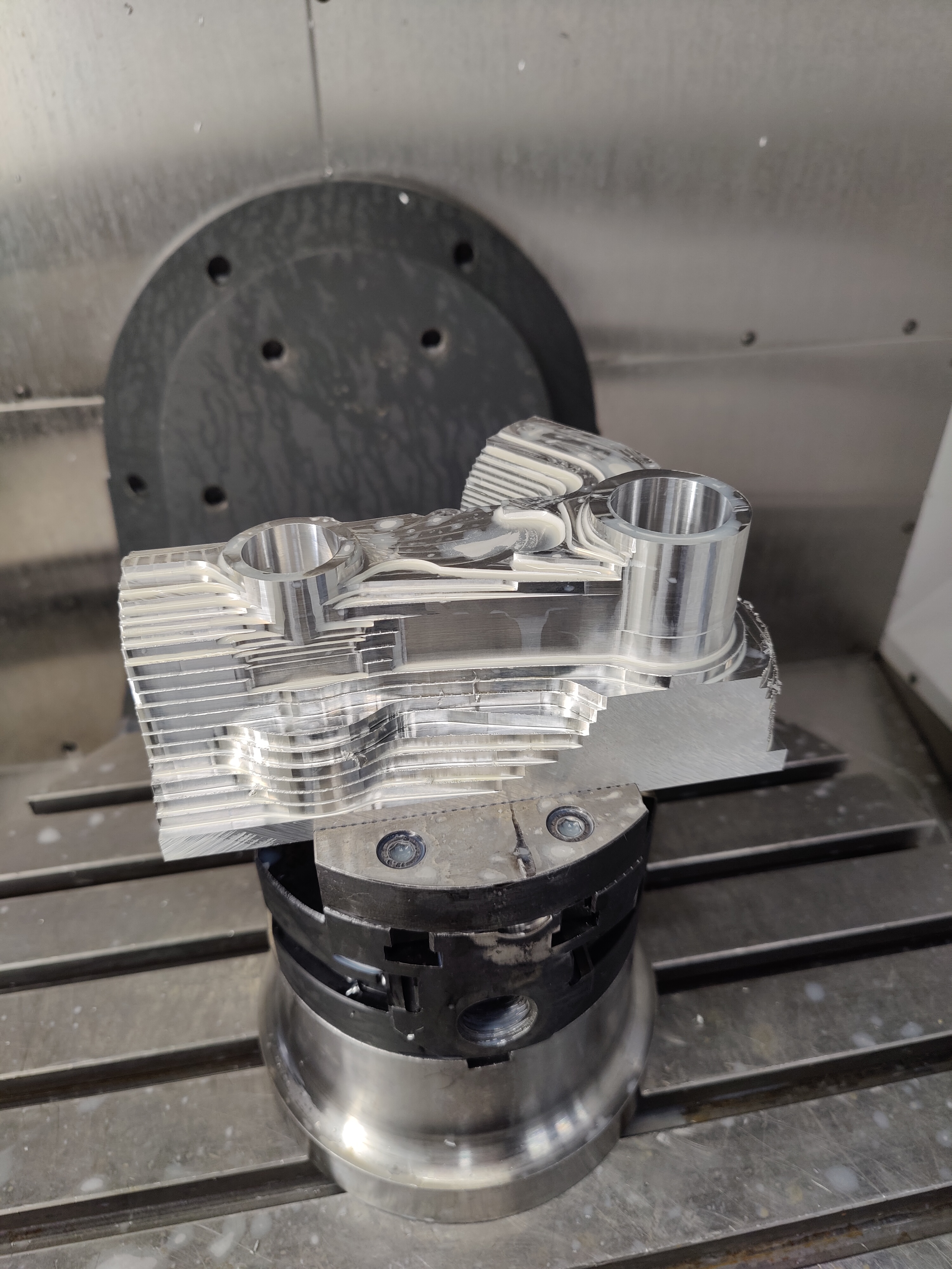
Most of the deep material removal is done with just drilling and then using longer 20mm end mill. This is not fully optimized in regards to weight yet, since there is some excess material inside the deep holes. The weight is currently around 400g and is acceptable for the proof of concept.
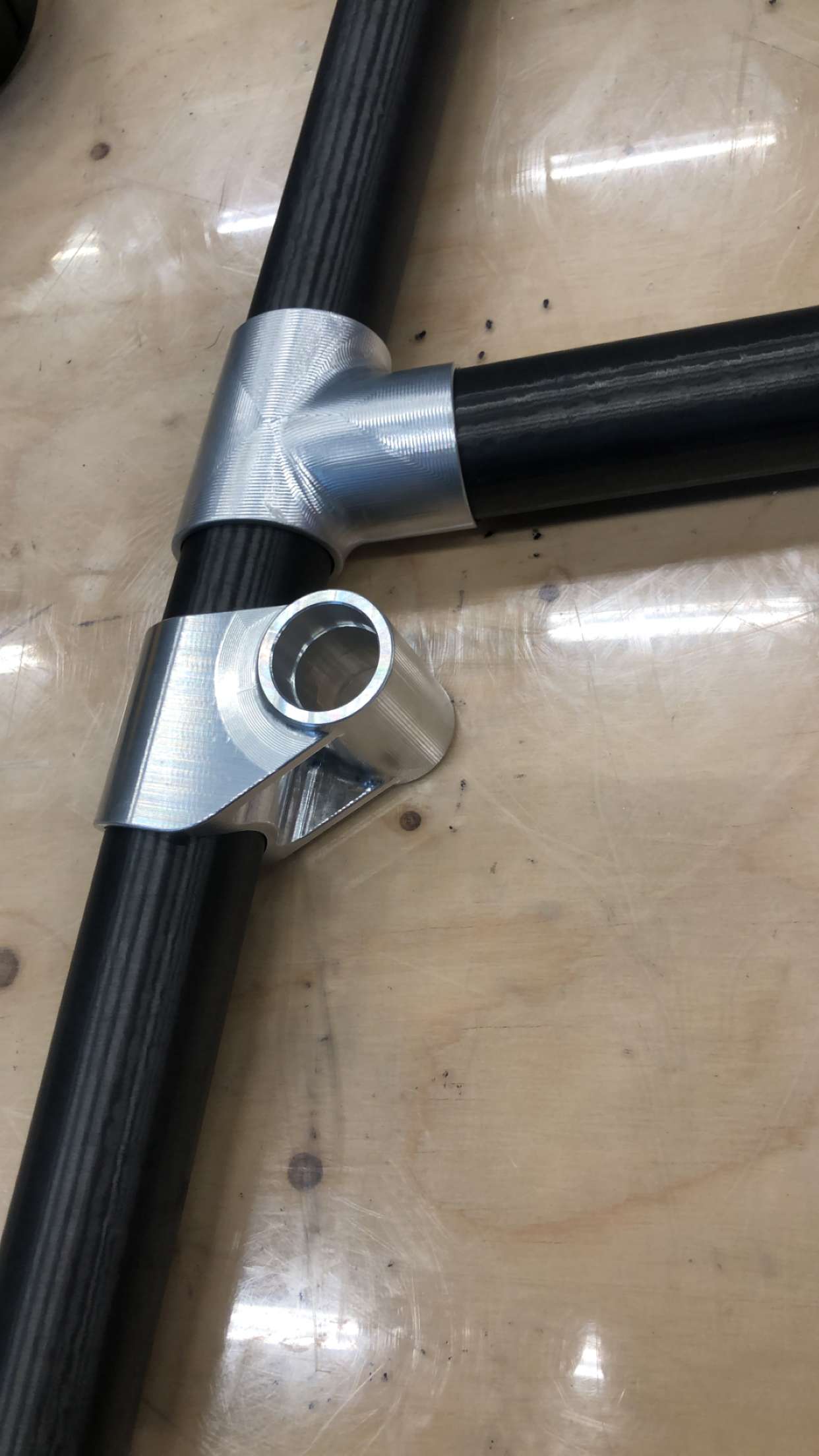
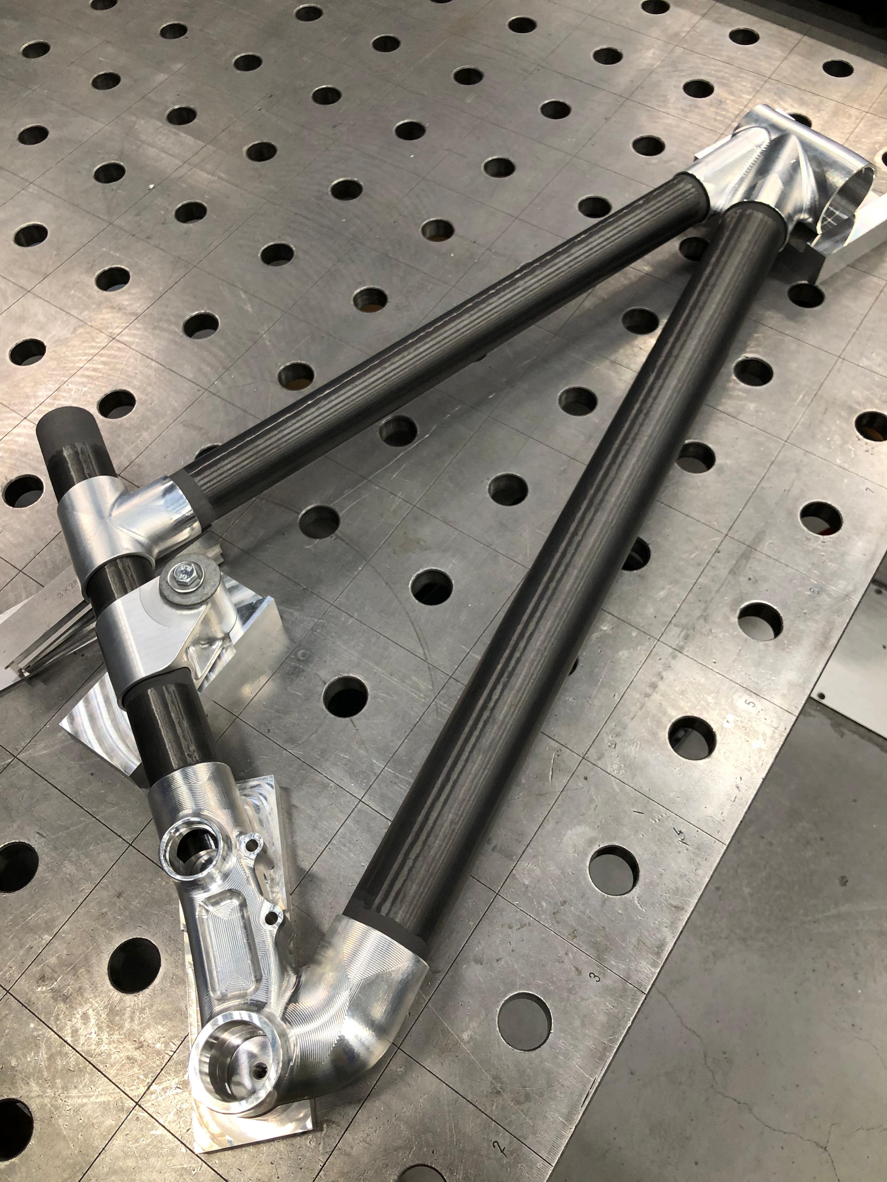
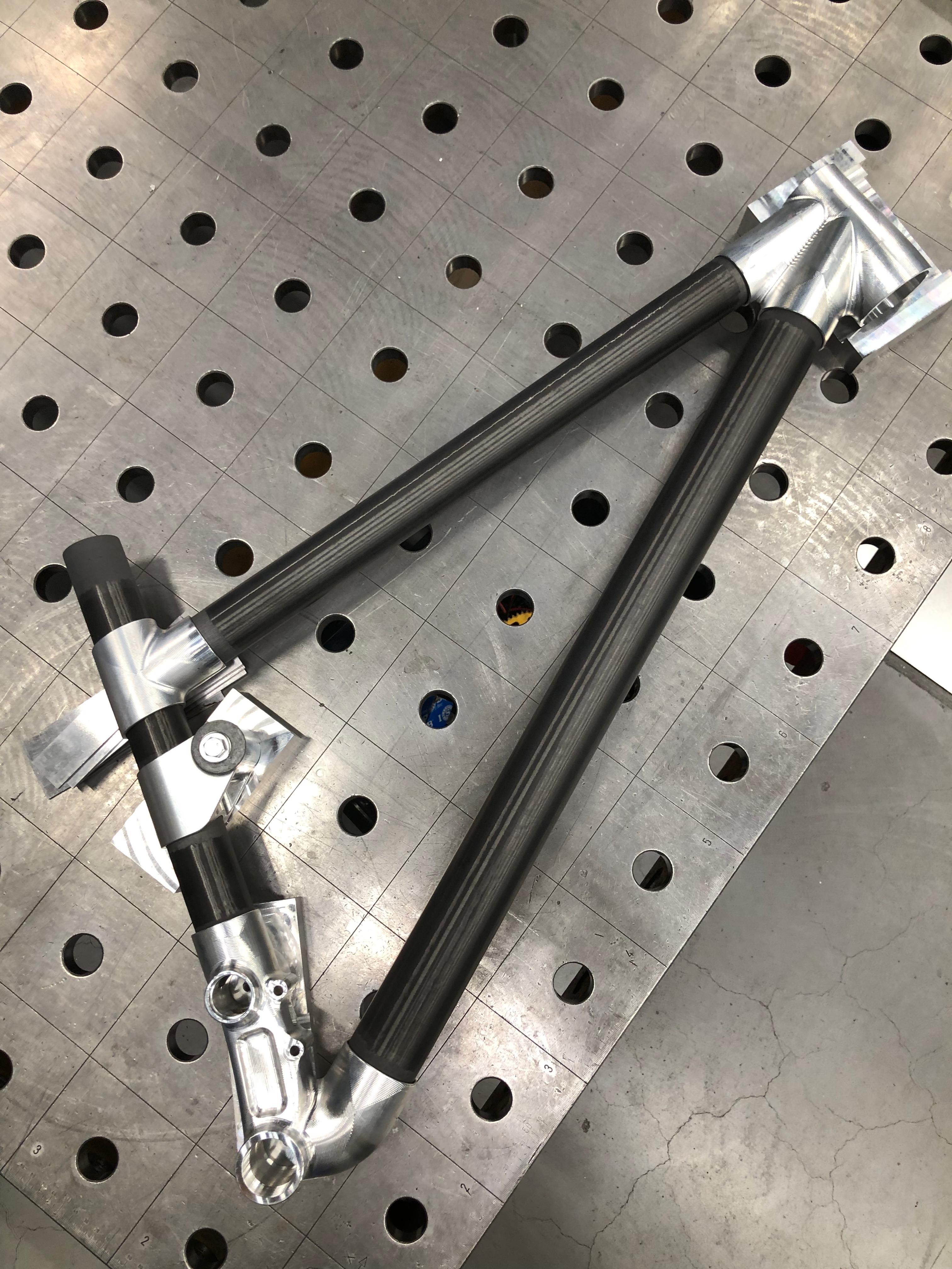
For the bonding jig I’m planning on using a welding table with machined parts to locate the components. Made some parts today and hopefully get to do some dry testing soon to see if it seems like good to go.
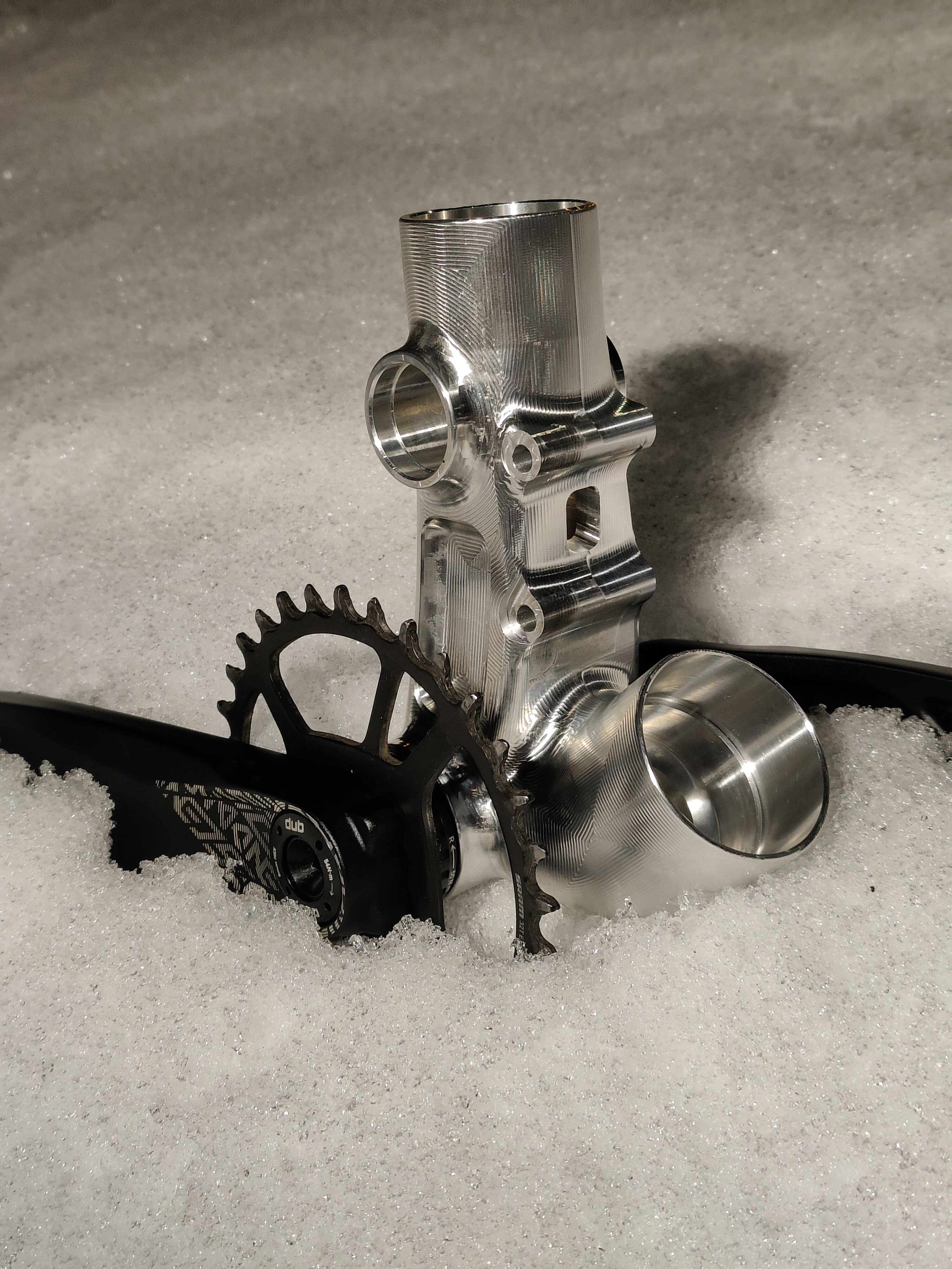
Got the tubes cut and prepared the bonding surfaces. Did some dry fitting and I have to say that it looks so amazing to finally see it together. Still need to prepare the bonding surfaces on the lugs and make a small jig for the T joint. Hopefully can bond it together early next week!