Weight Weenie Gravel Bike

Hey all!

I had to pick up a “real job” again which means I’ve had a lot of quality time in Fusion and not a ton of time in the shop. The obvious course of this is to engage in the beautiful art of weight-weenie dithering. I’ve never been partial to counting grams, but it ends up imposing some fun constraints to a design and thought it would be fun to try out. I’d been curious about composites but didn’t want to go all-in on learning carbon fiber fabrication so I decided to go half-titanium half-carbon fiber design. It might end up being a bad idea but at least it’s an interesting one :slight_smile:

My goal with this project is to create a gravel race bike. Clearance for 40-54mm tires, 1x AXS only, and light as possible. I’m hoping to hit the 1.2kg mark, but I’m still a few theoretical grams over that. The dropouts, CS yoke, and seat cluster “lug” are all going to be 3D printed. The front top tube and bottom seat mast “lugs” will have their OD turned town to plug into the respective tubes.

I’d love a few more eyes on this. I’m a touch nervous about how much overlap to have on the Ti/Al “lugs”. I went with ~2x the ID of mating the carbon tube which according to the adhesive manufacturer should have a pretty adequate shear strength.


Component Material Weight
Head Tube - PMW EC34/EC44 Titanium 75g
Down Tube - Ø34.9 x .9/.7/.9mm Titanium 214g
Bottom Bracket - PMW T47 Titanium 84g
CS Yoke Titanium 84g
Chainstays Ø22.2 x 0.9mm Titanium 157g
Dropouts Titanium 110g
UDH Aluminum 26g
Seat Tube Bottom Lug Titanium 33g
Top Tube Front Lug Titanium 29g
Top Tube Ø31.7 x 1.6mm Carbon Fiber 120g
Seat Mast Ø27.2 x 2.5mm Carbon Fiber 194g
Seat Stays Ø14 x 1.2mm Carbon Fiber 51g
Seat Cluster Lug Aluminum 97g
TT/SM Bottle Bosses x5 Titanium 6.5g
DT Bottle Bosses x3 Titanium 3g
DT Cable Ports Titanium 11g
Total 1284g

Here are some detail pics of the 3D printed stuff:

13 Likes

This is great. Can’t wait to see the finished frame

One of the things that I’m trying to figure out is how small and light I can go on the down tube. To compare different option, I’m using a rough estimate of the flexural rigidity of different tubes. I thought it might be useful to share my process with this since I haven’t seen a ton written about tube selection, especially with different materials. To be clear, this is not a complete model of how tubes behave in a triangulated bike frame, it’s at best an approximation of how bendy different tubes are compared to each other.

I have several steel frames that I know and love well. I personally enjoy the feel of a “standard diameter” tubeset (25.4mm top tube, 28.6mm down tube & seat tube) but I want this gravel race bike to have a bit more rigidity to it, more comparable to an “oversized” 28.6mm TT/31.8mm DT steel frame.

I’ll start the comparison by getting a few equations together.

For a tube of consistent inner and outer diameter, the second moment of area is equal to I = π/32*(OD^4-ID^4). I’m going to simplify the butted tubes to just be their midsection since that is the part that will be subject to the most bending forces.

For 0.8-0.5-0.8mm tubes:

  • OD = 25.4mm → I = 6,605mm⁴
  • OD = 28.6mm → I = 8,715mm⁴
  • OD = 31.8mm → I = 12,044mm⁴
  • OD = 34.9mm → I = 15,989mm⁴

For straight-gauge 0.035" (0.889mm) tubes:

  • OD = 31.8mm → I = 20,872mm⁴
  • OD = 34.9mm → I = 27,801mm⁴
  • OD = 38.1mm → I = 36,409mm⁴
  • OD = 41.3mm → I = 46,632mm⁴

The next step is related to the properties of the tube’s material. We can find the Young’s Modulus (aka tensile modulus) for the materials we’re interested in:

  • 4130 steel → E= 205GPa (kN/mm²)
  • 3Al-2.5V titanium → E = 94GPa
  • Carbon fiber → Depends heavily on the layup used, anywhere from 70-120GPa

The next step is to multiply these values together to get the flexural rigidity. For example, the “oversized” Ø31.8 x 0.8-0.5-0.8mm steel down tube has a flexural rigidity approximation of:
D = E*I = 12,044mm⁴ * 205GPa = 2.47 kN*m²

Since Ti has a Young’s Modulus about 0.46 times that of 4130, we’ll need to pick a tube that has about double the second moment of area. A straight-gauge Ø34.9 x 0.9mm tube gives us:
D = E*I = 27,801mm⁴ * 94GPa = 2.61 kN*m²

But what happens if we want to fly a bit closer to the sun and try a fancy 0.9-0.7-0.9 butted titanium tube instead? That would result in:
I = 22,001mm⁴, D = 2.07 kN*m²
Which puts the rigidity somewhere in between the 28.6mm and 31.8mm butted steel tubes.

So that seems to answer one question, but there’s another one I’m still puzzling about. How stiff is the carbon fiber top tube and will that cause any issues?

Since CF is not an isotropic material like steel or titanium, estimating its rigidity isn’t super easy. Luckily the distributor I’m using to source the CF tubing has a spec sheet that lists its tensile modulus as E = 13.33 lb/in² = 92GPa. Like the other tubes, we can find its second moment of area to be I = 33,7671mm⁴ and roughly approximate its rigidity D = E * I = 3.10 kN*m²

From this, it seems like the top tube will be quite stiff compared to the down tube. That’s not usual when it comes to bike design and I’m concerned that it might cause issues as the frame encounters stress. To match the stiffness of the top tube, the down tube would have to increase to Ø38.1 x 0.9mm. Compared to the butted Ø34.9 x 0.9-0.7-0.9mm, that would add a whopping 72g. Is it worth the sacrifice???

2 Likes

For what it’s worth, I remember reading Jan Heine explain that when a top tube is as stiff or stiffer than the down tube it can cause shimmy. Not sure how accurate that is, but it’s something I’d try to avoid nonetheless.

3 Likes

Intuitively it feels wrong too! Seems like erring on the side of a more rigid down tube is the smart idea (which rarely aligns with the lightest weight option).

Perhaps also useful to this conversation, I found an old Bike Tech article on the subject:
Crispin_Mount_Miller_Tubing_Rigidity.pdf (969.4 KB)

2 Likes

Personally, I have had the opposite experience. I have found the bikes that shimmy are the ones that have a top tube that is not stiff enough tortionally. I don’t have the physics background to back that up but I do feel that clamping the top tube with your legs to get rid of the shimmy sort of proves the idea.

3 Likes

A math prof explains high-speed shimmy

Dear Readers,
I received a letter from a math professor pointing out that bicycle high-speed shimmy is not a resonance phenomenon like I said it was in a recent column; it’s a nonlinear bifurcation phenomenon called “Hopf Bifurcation.” So, I asked him to expound on this, and I’m putting it in here, because there may be some of you who find this as fascinating as I do.
—Lennard

Dear Lennard,
A linear analysis leading to resonance is appropriate for any system where there is an oscillator that is being forced at a special frequency — the resonance frequency — and when this happens, the amplitude can simply build to infinity. This is not what happens in bicycle instability for two reasons: first, there is no periodic forcing that causes the high-speed wobble (in fact, it can happen on a smooth road); and second, there is not a phenomenon that shows a characteristic building of amplitude.

Instead, the high-speed wobble is a critical phenomena, which is typical of bifurcations and bifurcation theory in general. Below the critical parameter value, you see one thing, in this case a stable equilibrium characteristic of a smooth ride, and slightly above the critical parameter, the smooth ride is no longer stable (but it still exists as an equilibrium, but an unstable equilibrium, just as standing a stick upright is an equilibrium but unstable because if it tips even slightly away from the exact equilibrium, it quickly drifts away), but the now unstable equilibrium gives way to a stable periodic orbit, which is the wobble. And as the parameter increases, the amplitude of the wobble can increase to some larger but fixed amplitude.

Also, Hopf-born limit cycles are self-exciting if you like to see it that way, as opposed to resonance that requires an external forcing to excite the resonance frequency. (For resonance, think of a bridge with a special characteristic frequency and if soldiers march over it moving their feet just at that frequency, then you have resonance; this happened when I worked at the Naval Academy when some of the midshipmen forgot to break step and they actually did crack a walking bridge!)

There are many types of bifurcations, and they explain all sorts of critical phenomena on nature, and this type, the Hopf bifurcation, explains the onset of oscillations in all sorts of natural systems, from population dynamics, to chemical reactions, to airplane wing flutter, to stability of steerers in bicycles, trucks on trains (leading to derailment) to landing gear wobble on airplanes.

To many engineers not in the know, these oscillations and their onset are often mistaken for resonance, but it requires a nonlinearity in a certain way. This is often guessed by the critical onset of the phenomena as a parameter is adjusted.

For the bicycle scenario, the parameter in the engineering phase could be increasing the stiffness build of the bike — a stiffer bike will be more resistant. The several design parameters could all be “nondimensionalized” to a single, non-dimensional parameter as is necessary to explain with Hopf since it is a one-parameter phenomena (this concept is called co-dimension-1 bifurcation). Or once the bike is designed and built, then the parameter is speed. Each bike has a critical speed at which it will cross the Hopf bifurcation value, and then steady state becomes unstable and wobble becomes the stable state. This, by the way, is why it is very, very dangerous to try those 150 mph downhill bicycle attempts!

I am including some video of the flutter phenomenon which is an aeroelasticity phenomenon — airplane wings oscillate — you have probably seen it out of your window of your last plane ride (hopefully if an airplane hits a bump in the air, the wing oscillates back to its stable loaded state). But if the airplane goes faster, this state becomes progressively unstable. At a critical speed, the equilibrium becomes unstable, and there is born a limit cycle, which is a state where the airplane wings oscillates at a fixed amplitude. But the amplitude increases with increasing speed. Each airplane has a critical speed marked on its airspeed indicator (called VNE standing for “Velocity Not Exceed”). I have read that the FAA marks this fastest “safe” speed as 30 percent lower than the actual critical Hopf instability speed to build in a margin of safety. Often the wings fall off if you go Hopf. That’s bad.

Video 1 >>
Video 2 >>
Video 3 >>
Video 4 >>

The Tacoma-Narrows Bridge is also often cited as an example of resonance, but it broke also because of Hopf — almost for the same reason as the flutter in airplane wings.

By the way, in bicycle speak, Hopf bifurcation gives rise to what is called “weave” as the stable limit cycle.

And also, there is another characteristic bifurcation in the cycle mechanics called “capsize,” which is due to another bifurcation called the “pitchfork bifurcation”. (Pitchfork is also responsible for all sorts of exciting phenomena, including beams buckling.)

Funny timing, your waiting until today to ask about this, because it was today that I was working in great detail in my graduate differential equations class about the Hopf bifurcation, so I had collected some of these videos yesterday. …

I just stumbled across this webpage that seems to, at a glance, properly cite both Hopf and Pitchfork to explain weave and capsize.

Wow, here is a whole book that includes the proper discussion of Hopf, and trains and cars, etc. And here is an article focused on trains. Here is a decent write-up about the technicals of what is the Hopf bifurcation, including its normal form (a universal form hiding in the equations no matter what the application, if it is indeed Hopf.
—Erik M. Bollt
W. Jon Harrington Professor of Mathematics
Clarkson University

Dear Erik,
That’s cool! I was taught in college physics class that the collapse of the Tacoma Narrows bridge was an example of resonance. This is amazing to find out now that it was not. And bicycle high-speed shimmy I understood to also be resonance oscillation.

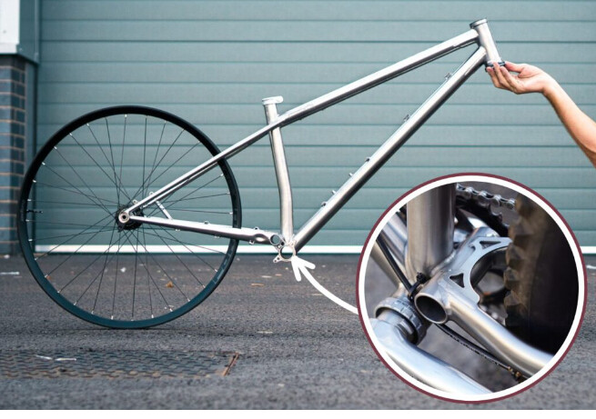
The good news is that the fix for the bicycle seems to be the same either way; making the frame torsionally stiffer and the wheels laterally stiffer deals with shimmy, whether it’s due to Hopf Bifurcation or resonance.
―Lennard

5 Likes

Regarding the article above, I think the most important sentence for us as the frame builder is the last sentence. The overall “shimmy” is dependent on both the frame torsional stiffness and the wheels lateral stiffness. Whether the wheels or the frame play a bigger role in the overall system behavior probably depends on the magnitude and ratios of the stiffness of each.

From the standpoint of the frame, the torsional stiffness is going to be a function of probably all of the tubes, but my guess is the shimmy is mostly dependent on the down tube and top tube “combined” stiffness. I’m envisioning that the twisting of the headtube gets resolved into lateral shears applied to the top tube and down tube. The down tube is “cantilevered” from the BB, and the top tube is “cantilevered” from the ST. The lateral displacement of the tubes is not only dependent on the material and section properties (EI) of the tubes, but also just as importantly, the length of the tubes. The longer the cantilevered tube, the less lateral stiffness it will have, for the same EI.

All of this to say, the down tube should have a larger EI value vs. the top tube, because the tube is longer. This could also be applicable for simply looking at the frame as a truss for more “typical” loading. Not to get too deep in the weeds, but a tube subjected to axial compression loads will fail at a lower load vs. the same tube with a shorter length. Due to buckling failure as opposed to a linear stress failure.

4 Likes

I don’t think what I wrote is the opposite of your experience. I was talking about the relative stiffness between the top and down tubes.

I agree that a top tube that’s too flexible can cause shimmy. But according to Mr. Heine, a down tube that’s less stiff than the top tube can also be a problem. That’s the problem @liberationfab may be facing with their design.

4 Likes

Agreed! Both TT and DT contribute to torsional stiffness. I think the DT contributes more, but both are important.

@liberationfab sounds like going up in DT stiffness goes against your initial design intent to match a 28.6 31.8 steel frame?

The way I look at it: durability and ride quality are the design parameters, then the bike weighs what it weighs. If the durability and ride quality are optimized, then the weight should be optimized.

Looking at your design, a 32x.9 titanium TT might be lighter compared to the carbon top tube. It also gets you closer to your stiffness goal.

1 Like

…but does it look as cool??

I’m fine with a bit stiffer than the original design, I just don’t want flexier. I may try to see if I can find some semi-custom carbon tubes too, these are just the off-the-shelf options from Rock West.

2 Likes

In Fusion, you could set up two FEA models to compare the front triangle lateral stiffness.
Grab the baseline from the 28.6 31.8 steel frame by fixing the BB and ST opening and measuring deflection at the headtube for a known load.

Then compare that number to an isotropic version of the carbon bike using the supplier’s material specs. This should get pretty close to comparing tubing wall thickness/butting profile changes.

1 Like

This would be a great excuse to learn FEA! Something I’ve never had an excuse to do before.

4 Likes

Credit to @PineCycles for sharing this info a while back, but Scott Nielson, the former VP of R&D/Engineering at Enve, started his own composite manufacturing business and has something like 120 different mandrel sizes for making roll wrapped composite tubing. I don’t know if he’s able to support one-off custom projects, but the bike industry connection might make it worth reaching out, at least.

Origen MFG

I apologize, you are correct I misinterpreted what you wrote. I am in agreement about the relative stiffness of top and down tubes being contributing factors.

2 Likes

This is a seriously cool design and I’m looking forward to seeing how it plays out. I think lugged carbon bikes are awesome.

I have a couple questions. Firstly, what adhesive will you use? Secondly, what is your reasoning for using carbon on some tubes and not on others? From what I understand, the DT and CS are more in tension while the TT and SS are in compression so I could see not wanting to rely on the adhesive in tension.

Thank you!!

I’m planning on using 3M DP460-NS. Seems like the de facto standard for composite bonding. The big reason for only using CF for a few tubes is that I don’t fully trust this process yet and there are fewer consequences/forces on the “upper” tubes than the “lower” ones. I’m hoping that gives me a bit of leeway for the inevitable mistakes I’ll make on this frame.

2 Likes

Oval TT - Does anyone have oval carbon top tubes that you could use? That may help with the overly stiff TT to DT ratio and would be sexy! Def reach out to Scott at Origen. They purchased all the old ENVE Mandrels and I would bet they have expanded the line.

Atherton Lugs - Have you looked at how Atherton (Robot Bike Co) Make their Lugs? They create a well for the tube to be inserted so they can get maximum adhesion on all sides of the tube. I’d be willing to bet the print would be a little lighter (cheaper) and create a stronger bond. That said the old Trek’s that used your current method were bombproof.

Raised Chainstay? - Have you considered this? I’m surprised more metal builders don’t explore a raised chainstay. It’s not really possible with carbon because the height of the cross section wouldn’t allow for it but with skinnier tubes you have room to move the CS axis upward to make room for tires while still having enough room for chain. It looks like the CS axis is already raised a bit on your dropout so a raised CS might allow for for a shorter CS Tube and smaller and lighter yoke if you’re really counting the grams.
image

1 Like

I haven’t updated this thread in a sec, but I finished the design and sent everything off to be printed! I’m still fussing over some of the bottle boss locations. It’s a bit too “warty” for my taste, but I want to have a fully bolt-on frame bag.

It’s been interesting playing with the fitup of the various “lug” pieces. Predictably, none are 100% true to size so I’ve had to do a bit of massaging to get them to fit nicely with the carbon fiber tubing I have. The yoke was also a bit distorted. I’ve tried bending it, but titanium is tough stuff! I think I’ll try to massage its fitup with heat when welding. I decided to roll the dice and print all of these with a 1.2mm wall thickness. Obviously I can’t say if this is “safe” or “real dumb” but so far it all feels super solid.

Here’s a dry fit of the rear triangle. Everything fell into place neatly which is a huge relief!

I thought about trying to mill a slot for the internal routing but drilling and filing was way easier.

Here’s a fun table showing exactly how much cash I have transmogrified into metal and composites. Not to mention all the lightweight components going on this frame :melting_face:

14 Likes

To touch on one of my original questions, I ended up following @PineCycles’s advice and using double sleeved lap joints for all connections. What sold me was reading about how that style of connection guarantees epoxy coverage in a way that single-sleeved lap joints can’t. Since there are a ton of variables at play, I wanted to at least be reasonable sure I was getting as close to 100% glue coverage as possible.

To figure out the bond length for each tube junction, I took the yield force of a “standard” butted steel tube and used that as a minimum for the shear strength of the joint. This is not a true proxy for the stress the joint experiences but it’s at least a decent ballpark estimate. I then derated the shear strength (nominally 4500psi or 31MPa) of the epoxy by about 75% under the assumption that there would be several non-ideal element in terms of bond gap, surface texture, or adhesive preparation. I’ve read just about every scientific paper under the sun about bonding additively manufactured metals and the conclusion I came to was that unless you can control all the myriad variables it’s best to just build in a substantial margin for error.

I ended up using a bond length of 25mm for the top tube and seat mast connections and 20mm for the seat stays. Those numbers were a balance of weight, part complexity, and margin. Using the ideal shear strength of the adhesive, all bonds are rated for over 400% the expected maximum force.

6 Likes