We (not project12 but 11Ants) have been building titanium frames for some time now, and we have an excellent welder and a lovely box filled with CNCed dropouts and other parts. Now we are looking for some updates on 11ants frames and I want to make my Victor in titanium with some 3d printed goodies. I have excellent experience with 3D printed stainless steel and silver brazing those parts but not a lot with welding 3D printed parts in titanium. We have an excellent printing company (Madit from Spain) that gives lots of advice and tips but I was wondering if anyone here has some experience they care to share? We already received some non heat treated samples that welded OK but didn’t feel that robust, and I am currently waiting for some heat treated parts to do some more tests with before I send them a printer full of goodies.
Nice, I am guessing these are yours:
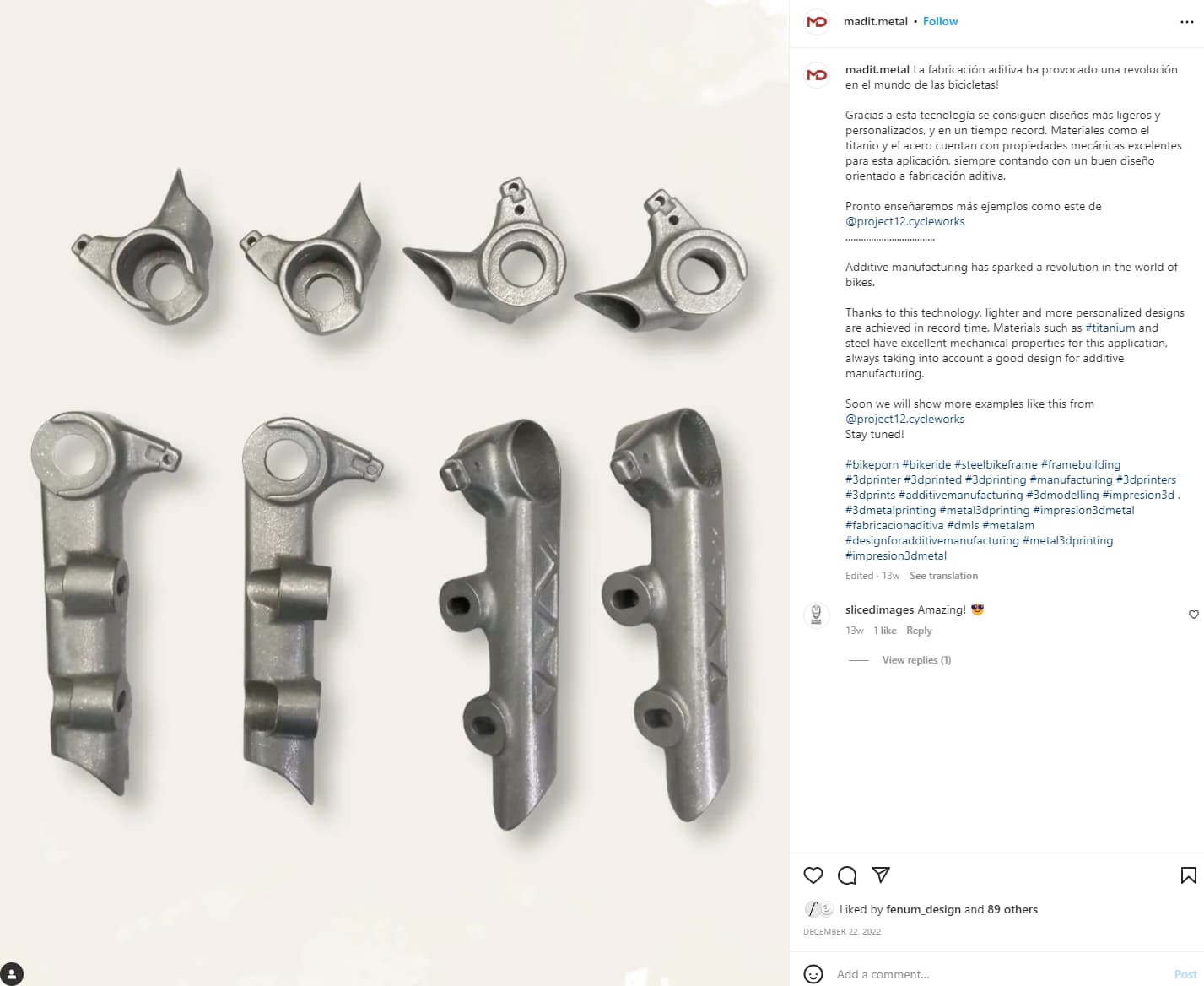
They look great!
@Neuhaus_Metalworks can comment more on the welding process, but I can speak more about the printing.
What makes you feel that they were not as robust? When I pick up our Ti parts, I get scared of how light they are ![]() but I have to trust the documentation and analysis.
but I have to trust the documentation and analysis.
They should be able to provide you with the mechanical properties of the heat-treated and not-heat-treated material. I would ask Madit to provide that documentation. When dealing with a new printing partner, I recommend printing some test dogbones as a sanity check to ensure that the mechanical properties are close to the claimed.
The printing process is so variable at the moment. Different powders, printers, print settings, heat-treating temperatures, etc… create a lot of variability in the print process.
Correct, these are indeed mine! I must say they indeed look great and are a pleasure to work with. Waaaay to heavy to make sure they will last ![]() I’ve got the documentation from Madit and a couple of heat treated testparts are on the way so we should be able to verify stuff. Our welder has 30+ years of experience and is as picky as they come, so this new 3D stuff makes him a bit nervous, hence my question here.
I’ve got the documentation from Madit and a couple of heat treated testparts are on the way so we should be able to verify stuff. Our welder has 30+ years of experience and is as picky as they come, so this new 3D stuff makes him a bit nervous, hence my question here.
We print a small filler lip on our ti parts but in most cases I also add .028" filler to get the look and maintain structural integrity of the fused joint.
It looks like some of your parts (if the parts @Daniel_Y shared are yours) are a slip fit over the tube, I would treat these as a normal mitered joint, fuse then cap.
On the parts that create a butt joint I would do a single pass with filler but make sure settings if pulsed are allowing fusion of the entire part plug included. This generally requires more filer than usual.
It’s all about the settings, I find that my normal settings work fine but the more I work with all printed the parts the more I refine specific settings for each part based on structural and aesthetic needs.
The little fusion rings help out a lot for welding. I have been playing around with the best dimensions. It’s a bit tricky because those fusion rings are often printed as unsupported overhang. This leaves a “broken edge”. Which is fine because it gets melted. But in general, its best practice to minimize print defects because they could have an impact on the mechanical properties.
So far for the CS yoke, we are at a 1mm thick lip that sticks out 1.3mm
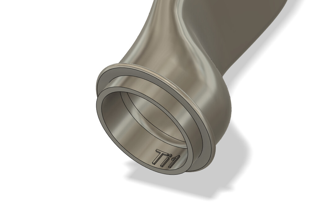
I think it could be a bit bigger, but as I said, I don’t want to put too much material on an unsupported overhang.
The parts Daniel shared are for my steel fillet brazed frames, the titanium frames will get a lip like Daniel shows in his last post. But thanks for the info, very helpful! Now to just put a couple of nights of work into finalizing the design ![]()
Actually I didn’t draw it the same I see now. I’ve made it with a lip that goes into the connecting tube, but not an upright lip that sticks out. I just saw a insta post from Prova and he seems to have done the same thing with his dropouts. But as I understand you use this lip as the filler, so in theory you don’t have to use separate filler and the lip is sacrificial? (But it might be better to use some filler also)
When we did the dropouts for the Routt RSL and then for the other flat mount frames we did several test welds from the printer in the UK on some parts he made for F1 in 2014/15. The material all tested out to be at least 95% as strong as billet 6/4 and the welding was clean. When we switched printers the welding had a different “feel” and some color but was still strong.
When I designed the prototypes and then the production pieces we had the “socket” on the chainstay plug in about 1cm and we fused and then welded the seam with rod. My gut feeling and the reality after a few thousand frames is that with a complete bike the stress on the joints is pretty small at the dropout when your thru axle is bolted in there.
Also, at least at the time, the minimum wall for the printed parts was 1mm which with 6/4 is thick and bomber. Definitely have the parts heat treated as that will take care of any residual stress in the parts.
As an aside, in the mid to late 90’s PMW made “Wright” dropouts as a 2 piece part. The flanged piece came off of the turning center and the hanger was a mill piece. For years we welded the hanger to the dropout, ground it down and then put it in the fixture. Giant PITA! Then I got the bright idea to make a bunch of dropouts out of CP with the hanger. Yes they bent easily, regretted that one. Then later we had the dropouts for our SL bikes (using Reynolds butted 6/4 tubing) made out of 6/4 and they worked great, never a problem. Things have come a long way…