Two slippery birds, one slippery stone, TT / pursuit bike brainstorm

an introduction to me:
Im long-winded when I write, I think its because I feel the need to establish context thoroughly, I do try and be concise, I honestly do, I guess I think a lot of stuff is important and im usually looking for a thoroughly considered response…

I’ve been kicking around on the forum with some small contributions for a while and enjoying the space and community, now it feels like the time is ripe for a build log; both to (hopefully) give something small back to this great community, and also to ask for help; mine-the-hive-mind a little for some solutions.

Im a hobby builder who’s built about 60-70 frames, mostly of the ‘rigid’ road/CX/track variety, but a few full-suspension mountain bikes too (all by shoe-horning off-the-shelf suspension components into a front triangle of my own design). i’ve previously had short periods of building frames full time but have settled on more of a slow-burn approach as a happier way to keep building bikes and loving how I do it.

I don’t usually document /much/ of the building I do, but having recently moved to Cairo (Egypt) im struggling to really engage with a frame building or industrial design community IRL like I would at home (in New Zealand), so moving this online is also my attempt at engaging with people for that shared enjoyment.

Finally this idea had been kicking around in my head for quite a while, and yet its still got some pretty curly details, so i’m hoping I can draw on the wider knowledge of you folk to bring this design up to a level where i’m happy with it.

an introduction to the context:

I’d like to build a frame/bike/system which I can, with relative ease, switch from being a competitive and elegant solution for racing individual pursuits (on a velodrome) to being a decently-configured road time-trial bike.

Straight off the bat id like to acknowledge that a lot of this is about aesthetic. people can be fast AF on just about any-old jerry-rigged aerobar/ bolt on derailleur setup, and that’s rad; in fact that’s am important part of what I love about bike racing, but that’s not what I’m after this time around. another important part of what I love about bike racing that it can also be an accessible space to design and build stuff in ways that we choose, and this lets us lead it (the racing experience) where we want it to go. So, Id like to build a bike that showcases my design ideology in a beautiful way, which I feel really good about “racing in both disciplines at a competitive club level”.

what “racing in both disciplines at a competitive club level” means;

Occasional, targeted weekends of individual pursuit races on (potentially varied, but likely mostly what will be my “home” two velodromes (indoor and outdoor)) , with practice sessions in the build up weeks/months. these don’t happen all the time but aren’t /uncommon/ throughout a season. upon my return to wellington id like to invest more energy in having a IP season and doing more of them.

in-between these periods, racing road TT’s (or team triathlon events) these are a lot more accessible (especially here in Egypt), most of the opportunities for organised racing here are TT’s of some description. there’s a tt club at home in nz ive never joined because ive never had a tt bike.

I’ve previously held our club hour record, given time, id like to hold it again.

an introduction to my ideas (as they stand at the time of this first post,) for the bike

so its just a rim brake TT bike that has a spare, 130mm spaced fixed gear rear wheel?

well, yeah; on the surface.

on a slightly deeper level, i’d like the bike to have some specific capacity for position-adjustability, and I feel there’s potential for some nuanced details surrounding brakes, drivetrain, etc.

drivetrain:

[this is the most resolved area in my mind. mostly because of the ease of adding/removing an AXS rear derailleur.]

on the track, a normal fixed gear drivetrain is a bit of a must, I have a full set of 1/8th" cogs and chainrings (144bcd) which I use for mass start racing, its not uncommon to want to change ratio for an IP based on conditions, especially in an outdoor velodrome, so having a “normal horizontal fork-end” type dropout is making sense to me at this point.

unless someone else figures out how to make non-round chainrings work more nicely than I’ve been able to on a fixed gear drivetrain (and believe me, I’ve tried…) , ill need to keep running round chainrings for track use, so using the existing set continues to makes sense here for this reason too.

i’ve been known to run cranks anywhere from 165 to 210mm (zinn ftw, but not really) on various track bikes i’ve built over the years. pedal strike has never been a problem, but I believe only because i’ve designed frames around a certain crank length/ pedal width. on the track i’m likely to run shorter cranks and a lower relative front end for a pursuit than I would for an hour record attempt, and I currently believe that having the BB as low as possible is an advantage.

on the road, Im imagining a 1x (10,11,12 whatever) setup using a sram apex AXS rear derailleur (which I can remove, maybe along with the derailleur hangar too,) and some fancy electronic button shifters I can leave in the aero-bar extensions all the time. I have no real desire to shift from the base bar, this means no cable or wire routing changes for the drivetrain, which is pretty nice.

ill definitely use an oval/non-round chainring on the road with an appropriate road chain. i’m happy to make one or two of these in 144bcd and thus keep track cranks on the bike for both setups, I have a range of track crank lengths I like to experiment with.

Wheels
[basically solved, I think]

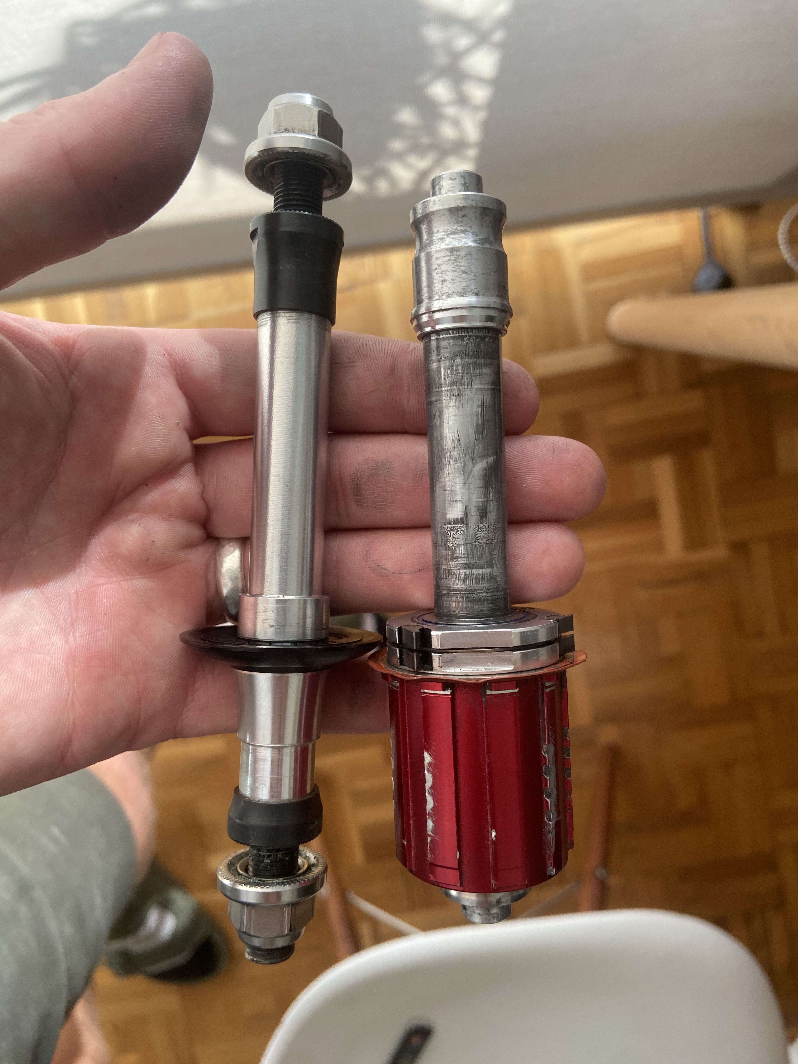
I have a tubular zipp rear disc that (to the best of my knowledge) uses the zipp 182 hub. I only have a track axle for it, but making/aquiring a road axle that takes a freehub body should be achievable. this wheel IS a little narrower than id like on the road but that’s OK, if a notably better solution becomes apparent, I’m not averse to spending some money on a new disc that works for both if it improves both setups.

front wheel will likely a deep road wheel or maybe a fancy 3/4/5 spoke rim brake-compatible option. pretty easy and common to swap this out on any given day/ for a specific event provided its a rim brake option on/from the road.

brakes
[totally up in the air, help]

I definitely think rim brakes of some description here are the best solution, given the existing rear aero-disc wheel that can work for both, the simplicity of setup, and the ability to sit around unused in a cold damp workshop parts-box for 6 months without developing issues, but i’m wrong all the time, so I’m interested in opinions here.

I’ll be building a fork (more later) so introducing a single-bolt rim brake hole in the normal place seems like the obvious solution for the front. having an entirely external cable here seems like its going to be the simplest way forward without being pretty annoying… but I also don’t feel like its ideal, you don’t see exposed cables on fast moving (or good looking) fish or birds. I don’t need full bar tape on the base bar so that wont cause problems; some grip tape will be ok.

the rear brake is a little trickier. potentially under the chain stays becomes an option, I feel either way requires a removable cable-routing solution. I have thought about omitting the rear brake entirely it, but I come back to thinking it is best to have one, especially given it’ll be in and out of track/road mode, and thus the likelyhood that I’ll set this up into road-mode and ride straight out the door on it is high.

Im not completely adverse to simply helicopter-taping a fully housed cable to the frame somewhere discrete, with some critically placed zipties for added run-what-you-brung-but-dont-die-doing-it factor.
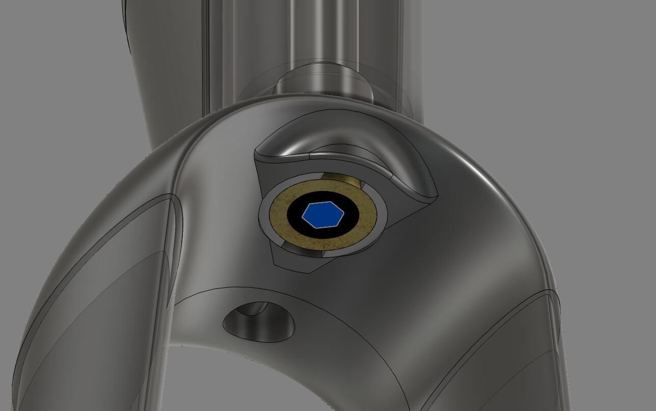
BB
[here is where the madness sets in]

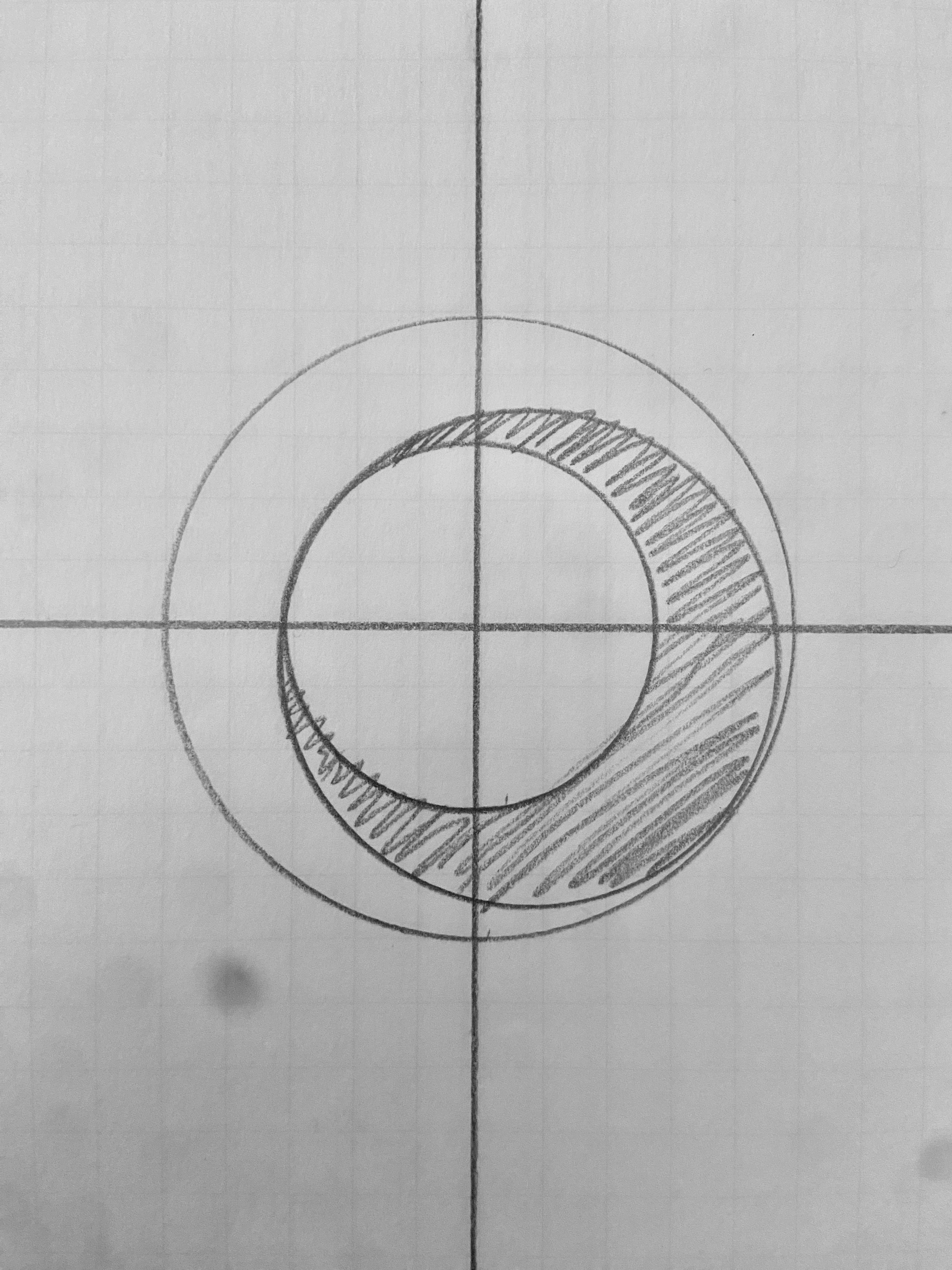
I think I want an EBB or maybe a VEBB (v is for very)

racing a track with 200mm cranks requires some serious bb height.

racing a short road tt with cranks that could be as short as 165 I believe would be much better with a far lower BB.

ive been doing some drawing of a simple ebb that could move between 55mm and 70mm of drop, but I think for all the Pfaff id like more range, 40 through 80 (mm drop) would be ideal.

this is a pretty unusual requirement, and thus its both not really serviced well by… well, anything.

I think I likely involves a pretty massive bb-shell-thing and machined insert which both might get quite heavy, and potentially pretty annoying to make.

it means the positional requirements of the saddle and handlebars will move A LOT in order to maintain relative position, and on the track these can also be limited in reference both to the front axle and the BB, AND my position is usually already on one or more of these limits. so it becomes a bit messy. it also potentially makes rear-brake-mount positioning more complicated.

positionally I really don’t need to move the bb forward or back, just up and down…
though sometimes, say for a record attempt, being able to tuck the rear wheel right in behind a shaped seat tube with any gear ratio on the track WOULD be kind of nice.
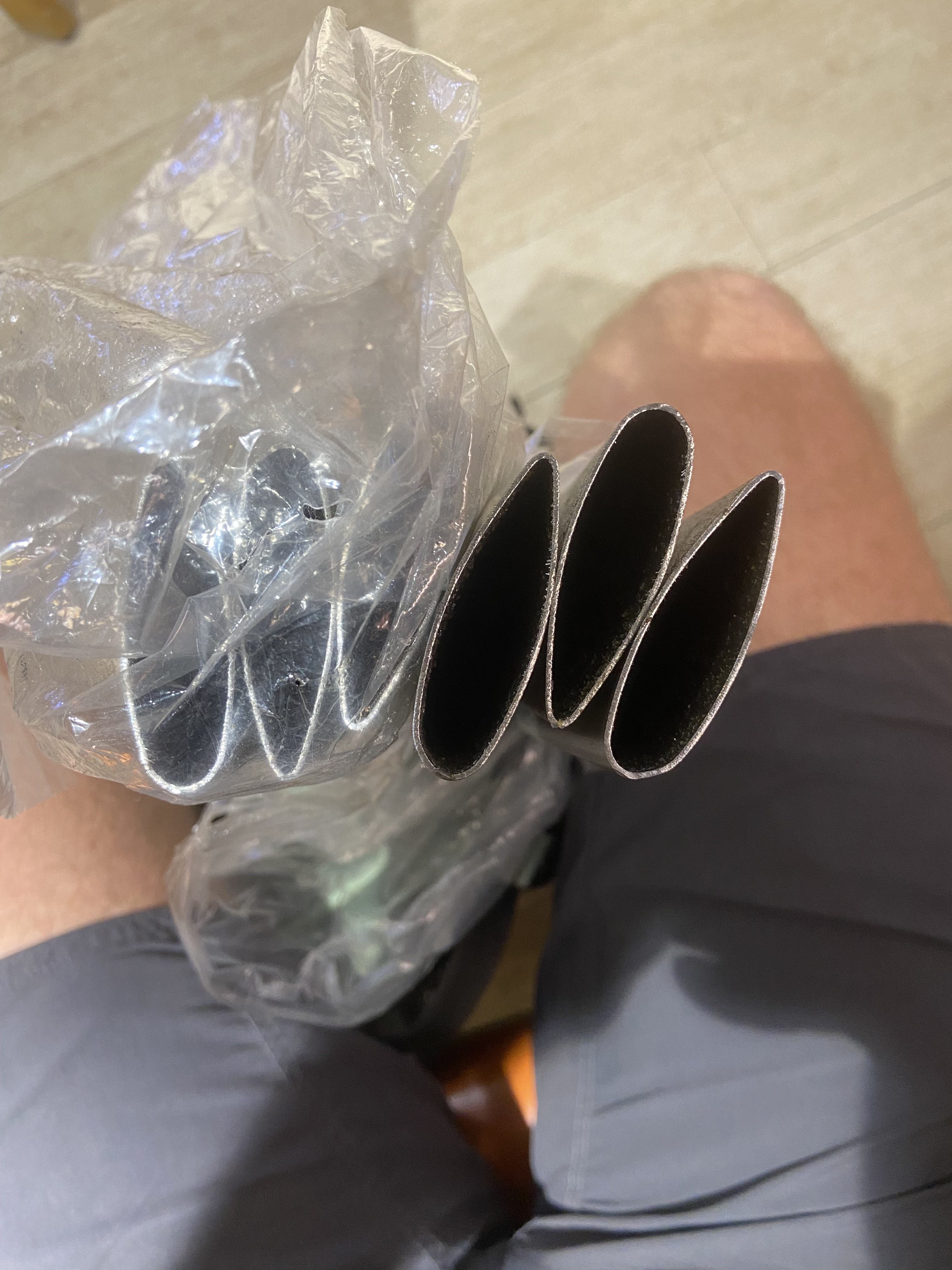
tubing

i’ve ordered and have a handful of options of streamline 4130, its often a case of what is available and what I can make myself here. but notably proformancemetals.co.uk have a wider range than most and seem happy to do small amounts to order.

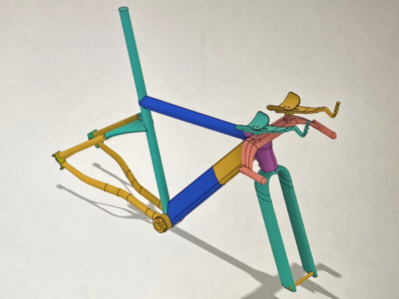
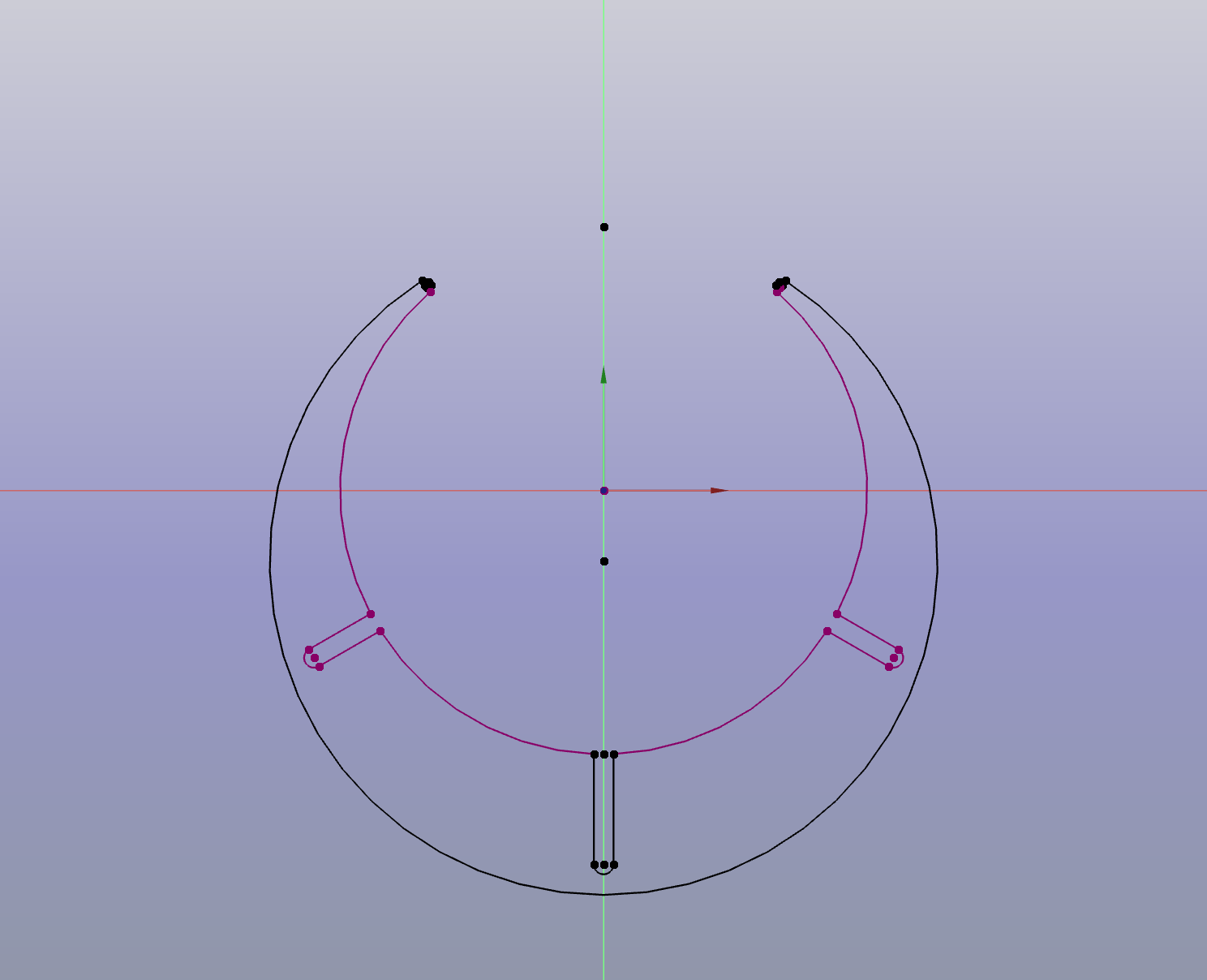
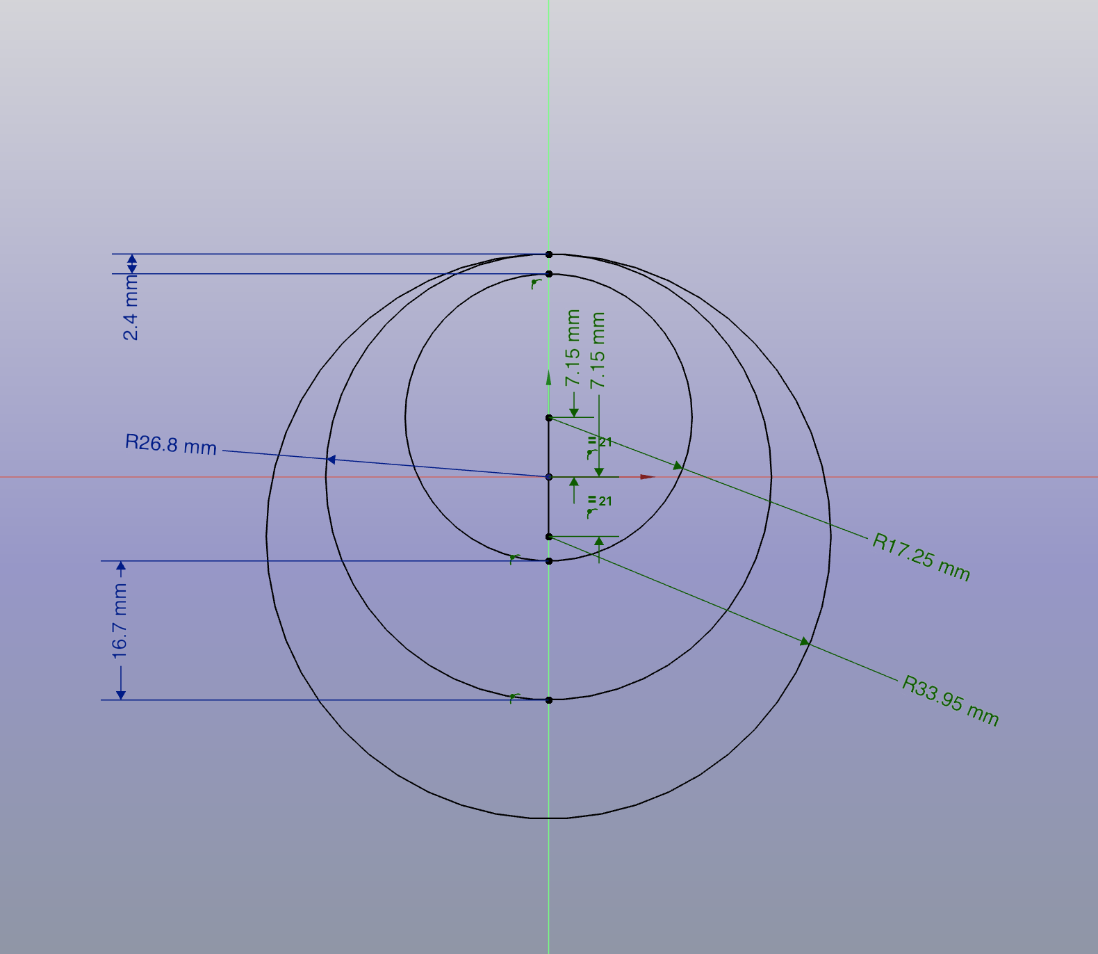
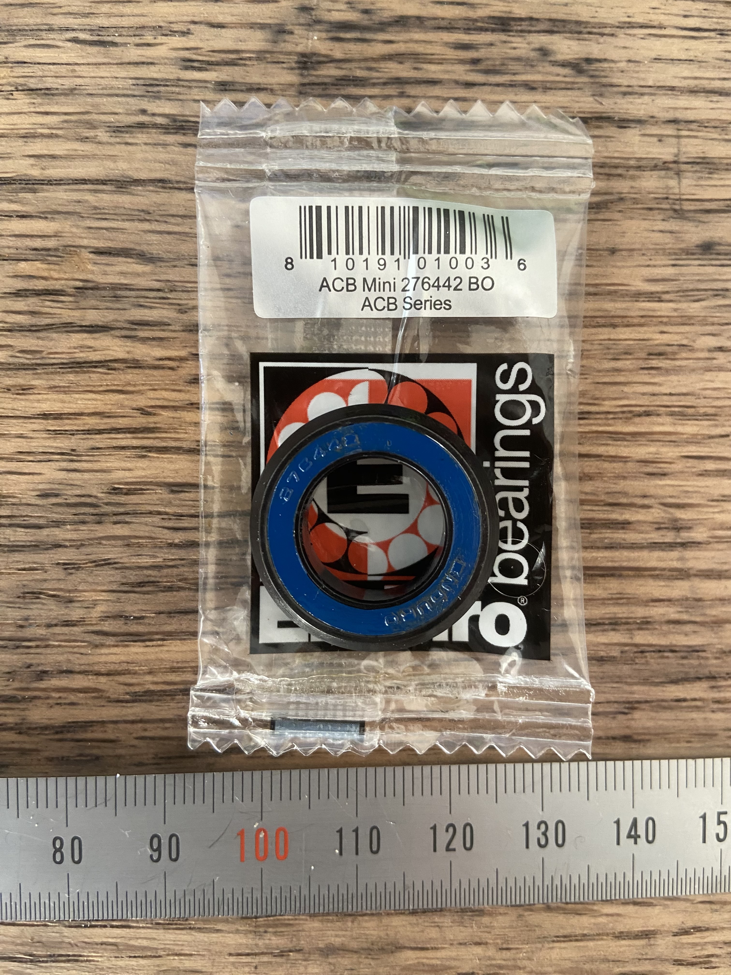
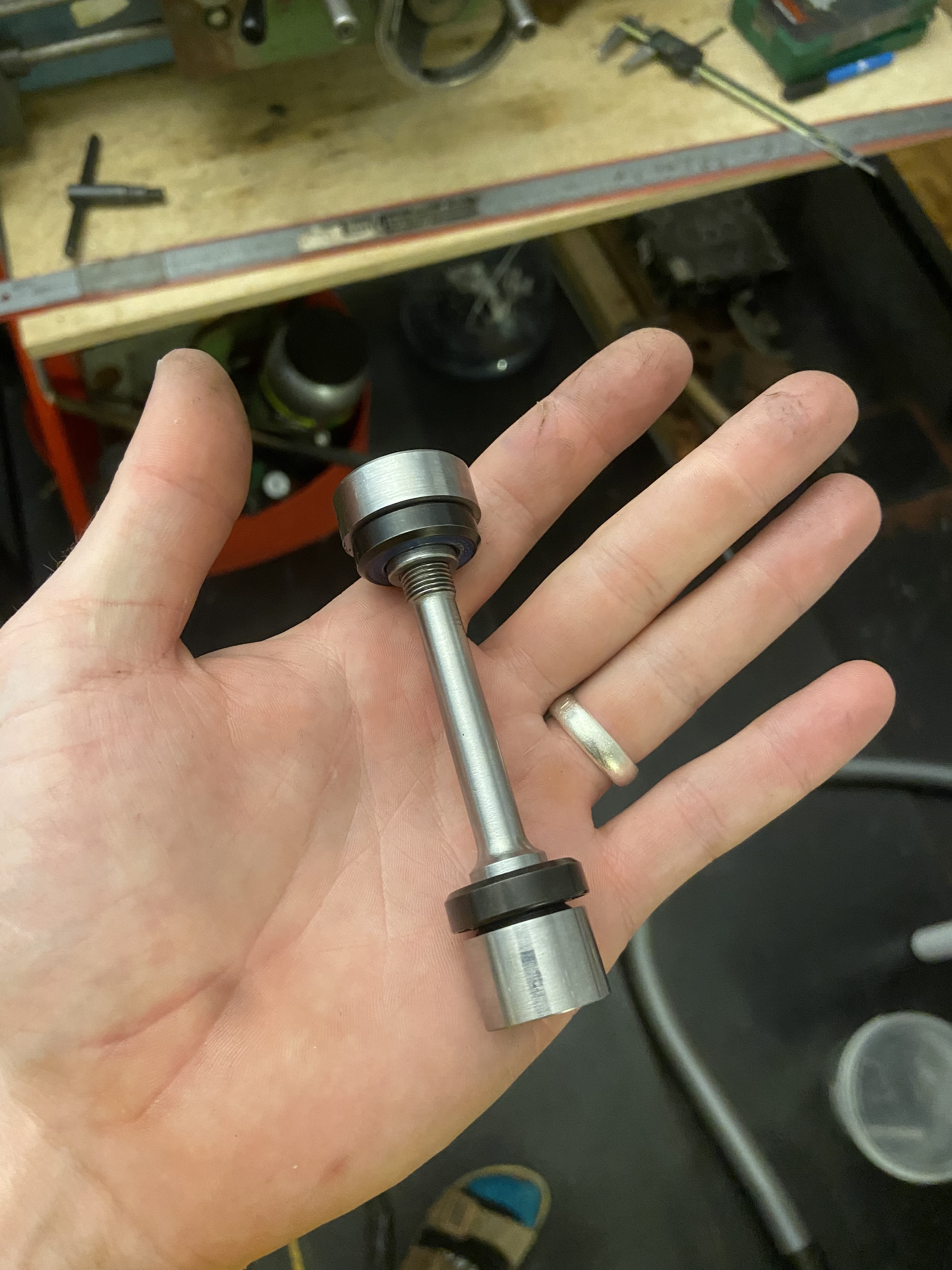
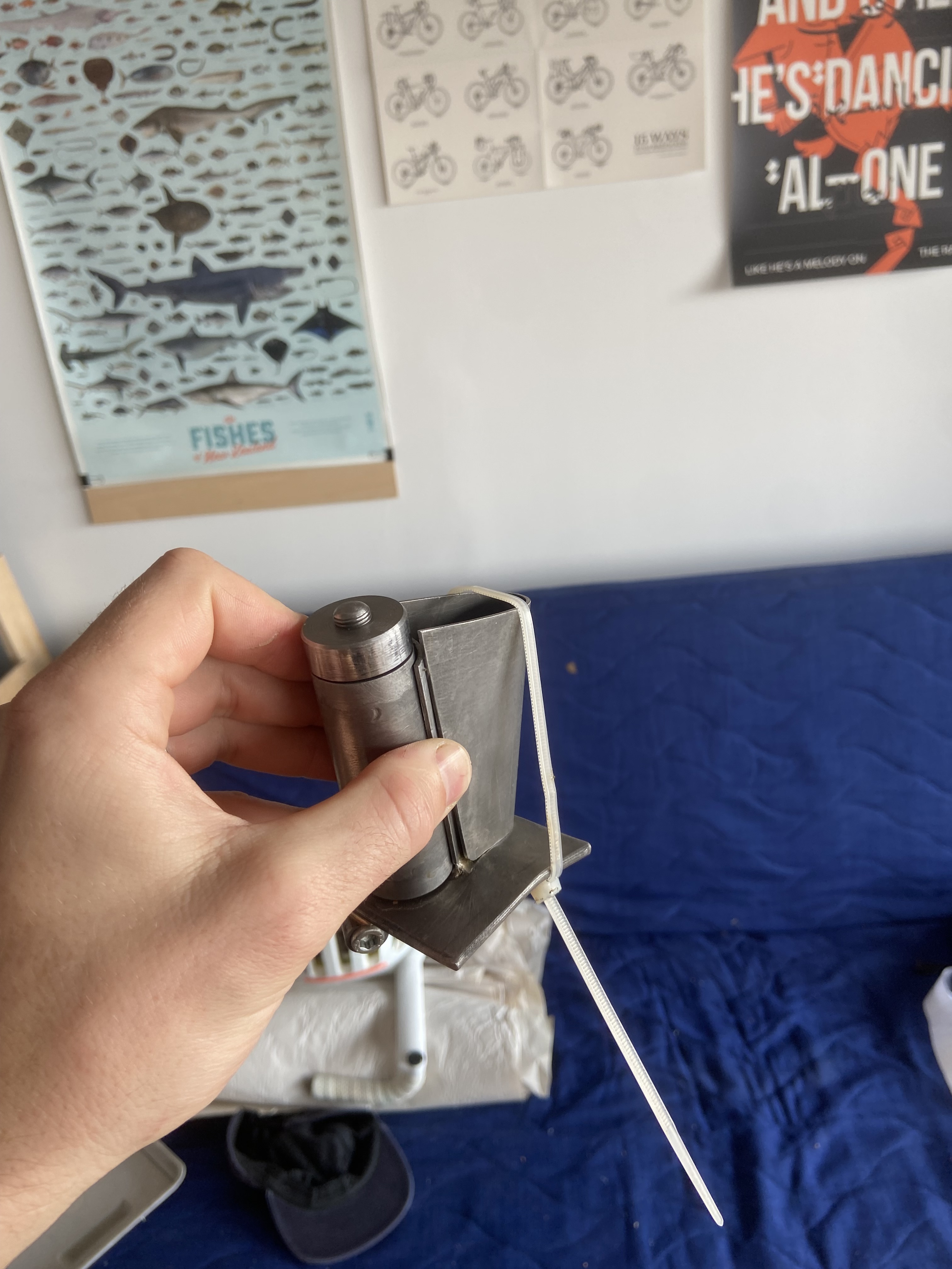
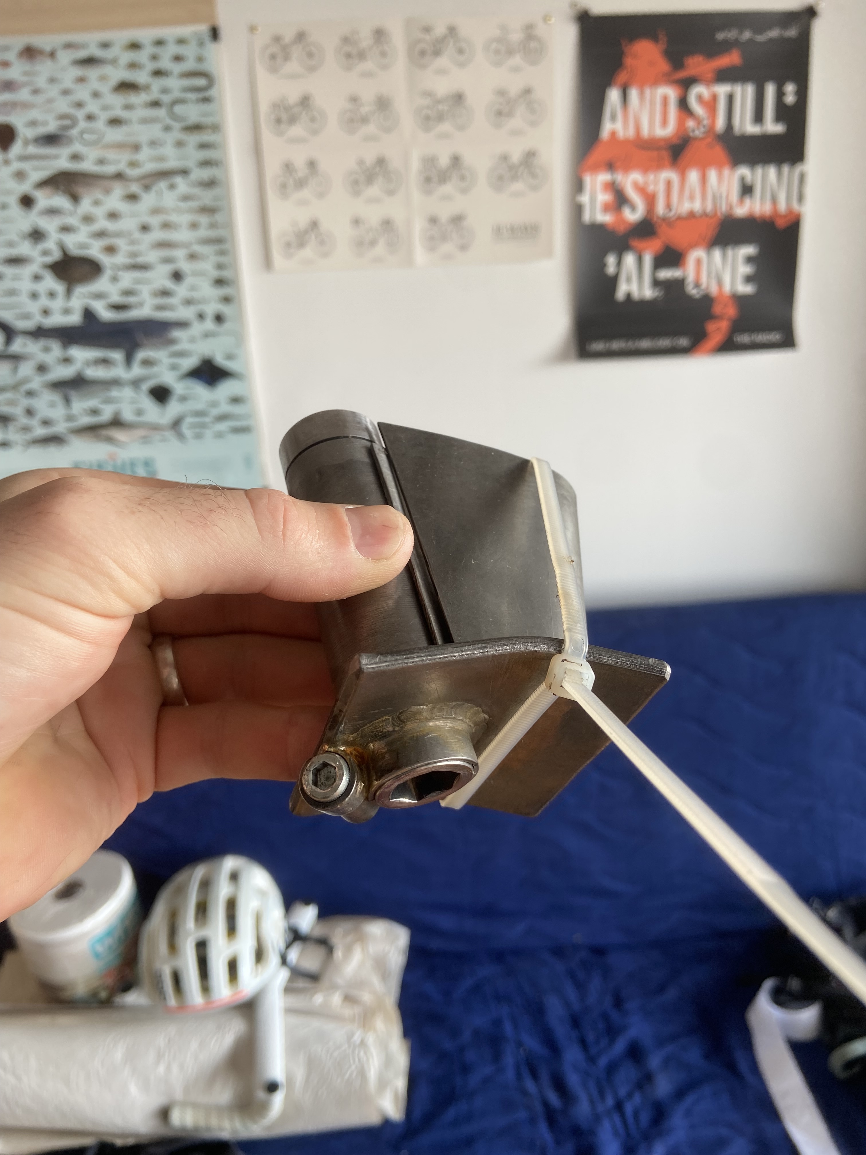
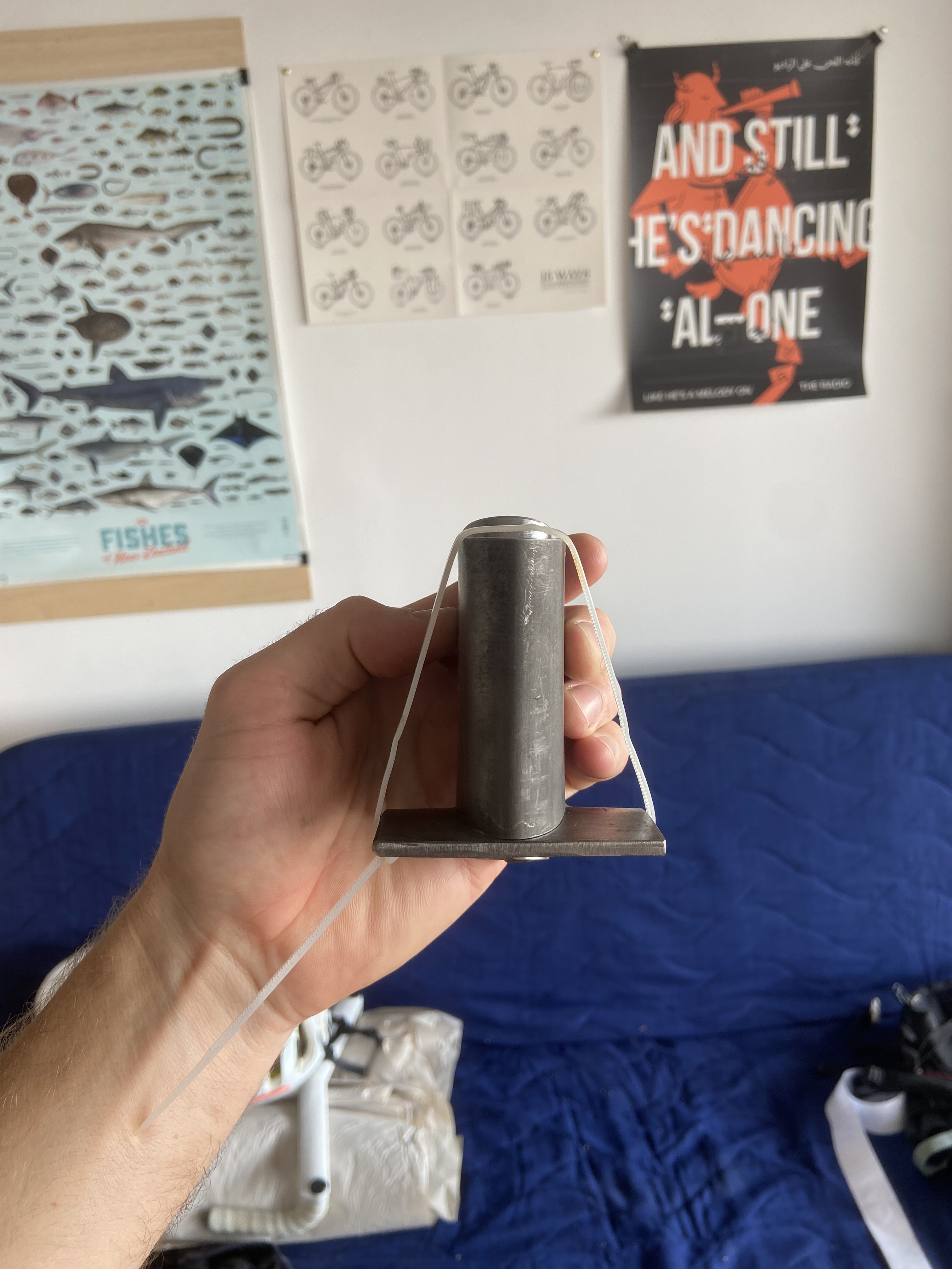
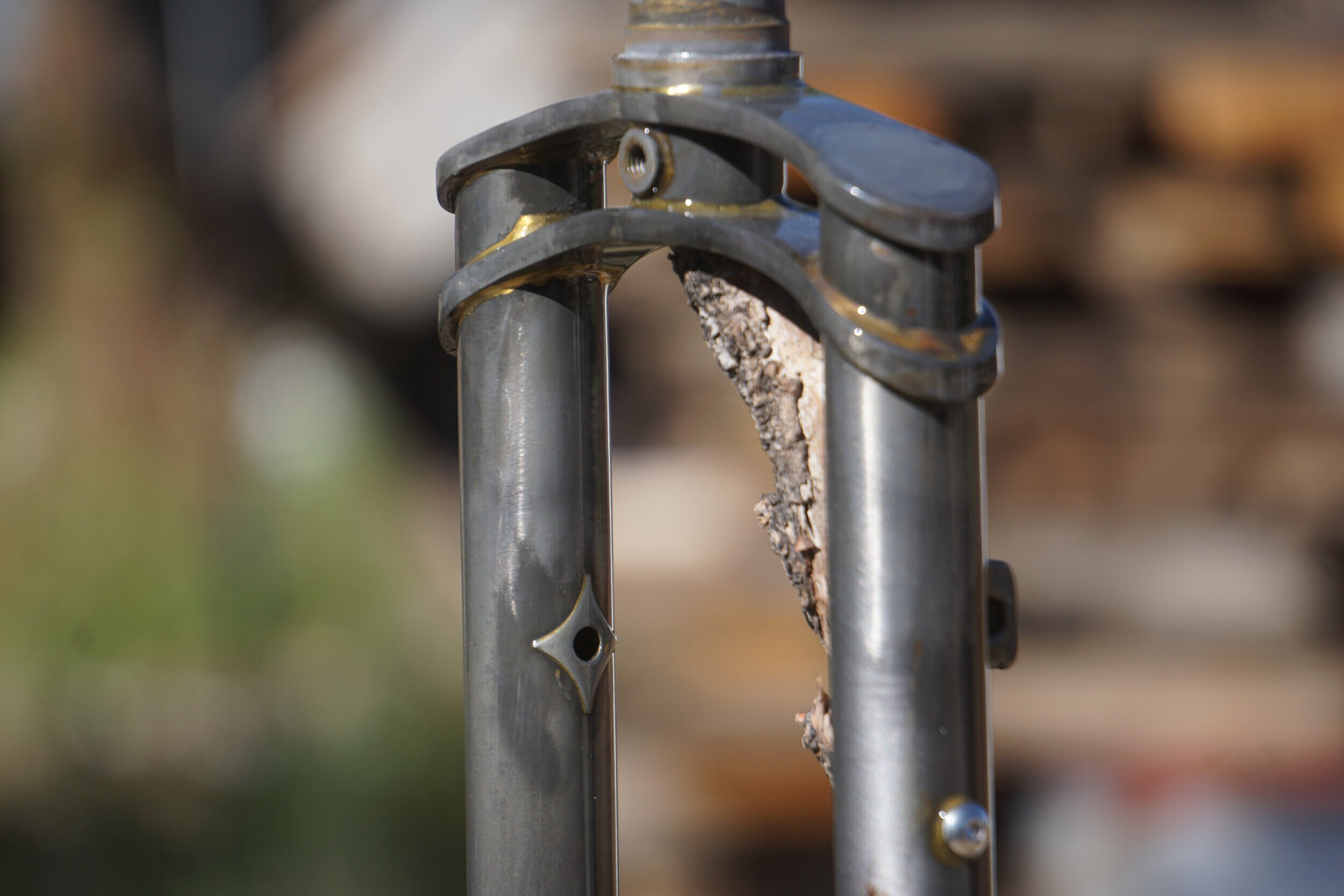
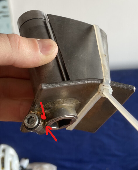
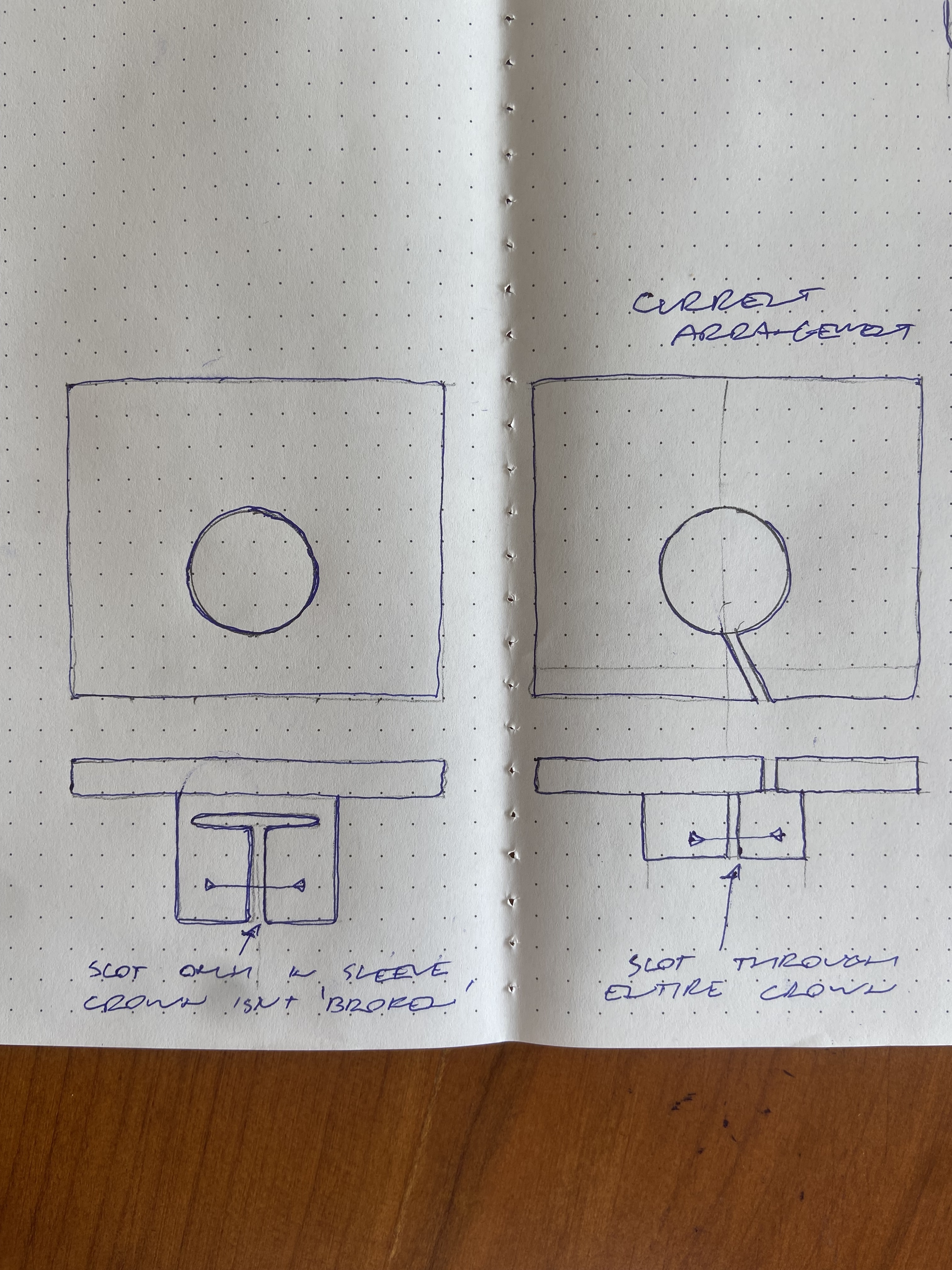
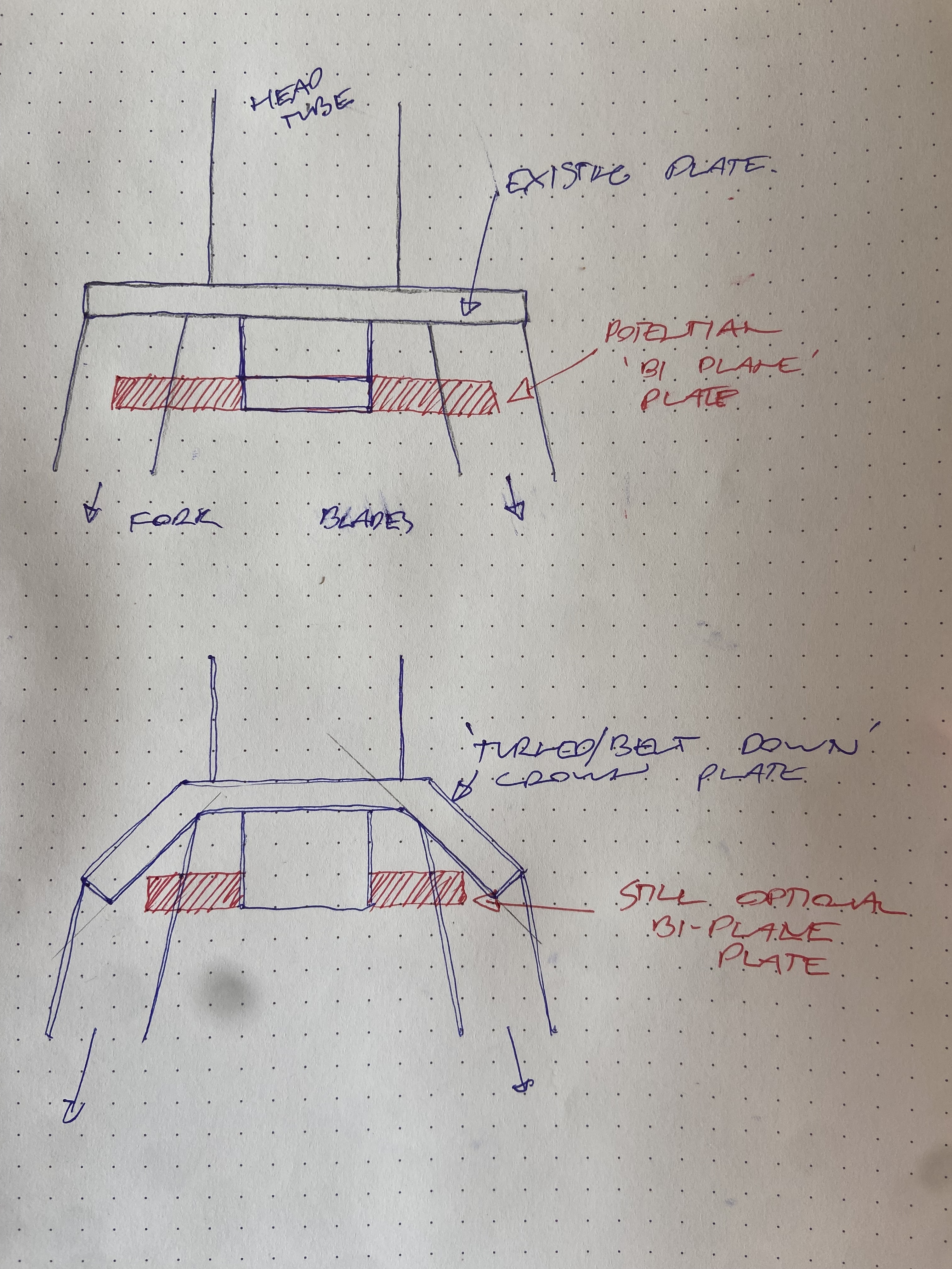
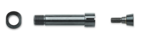
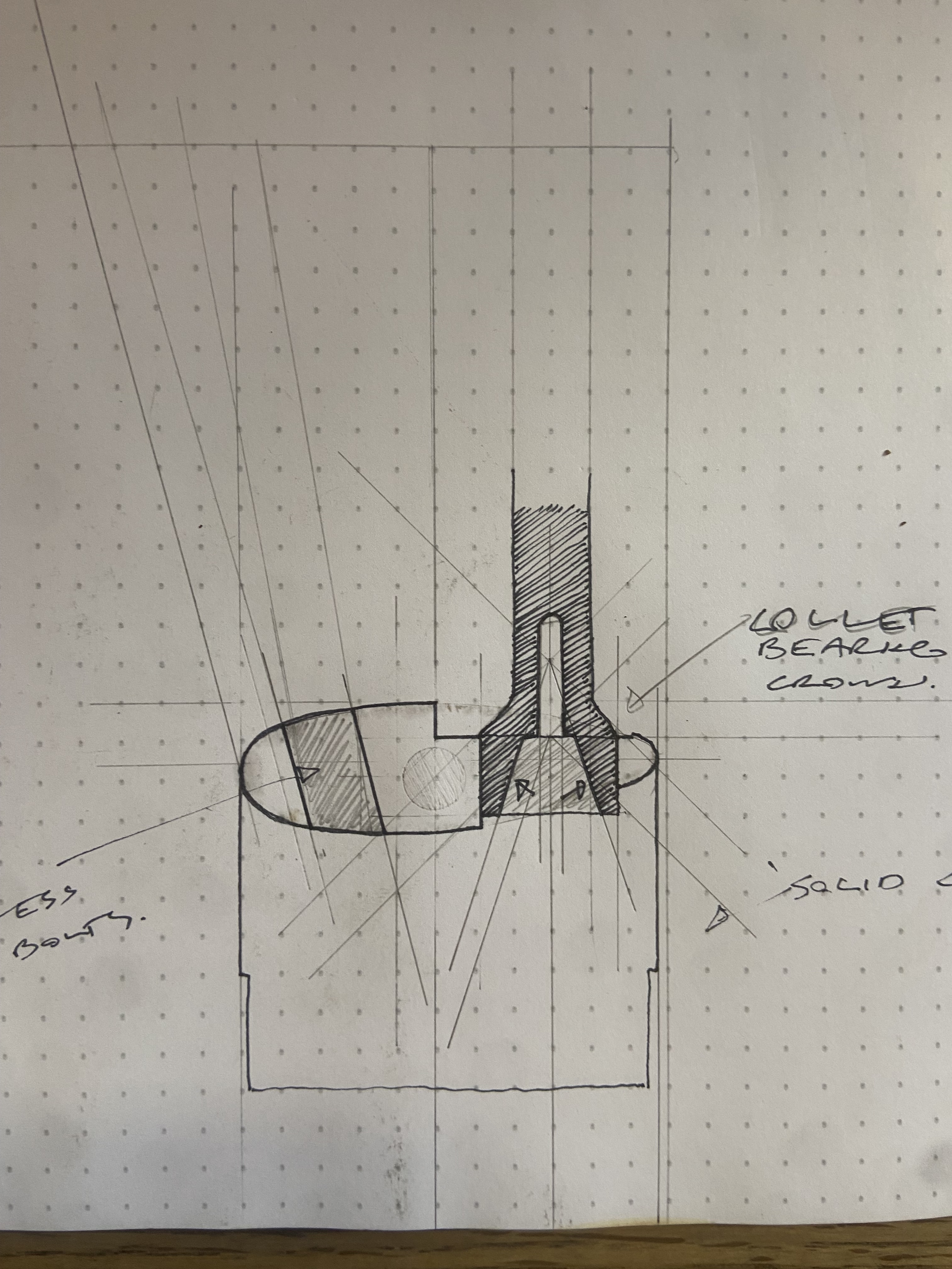
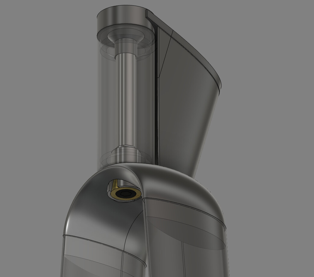
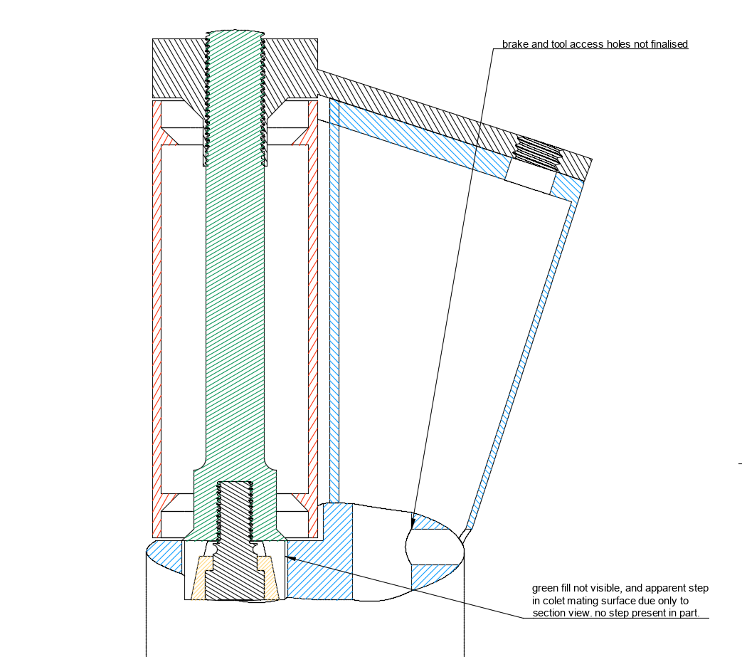
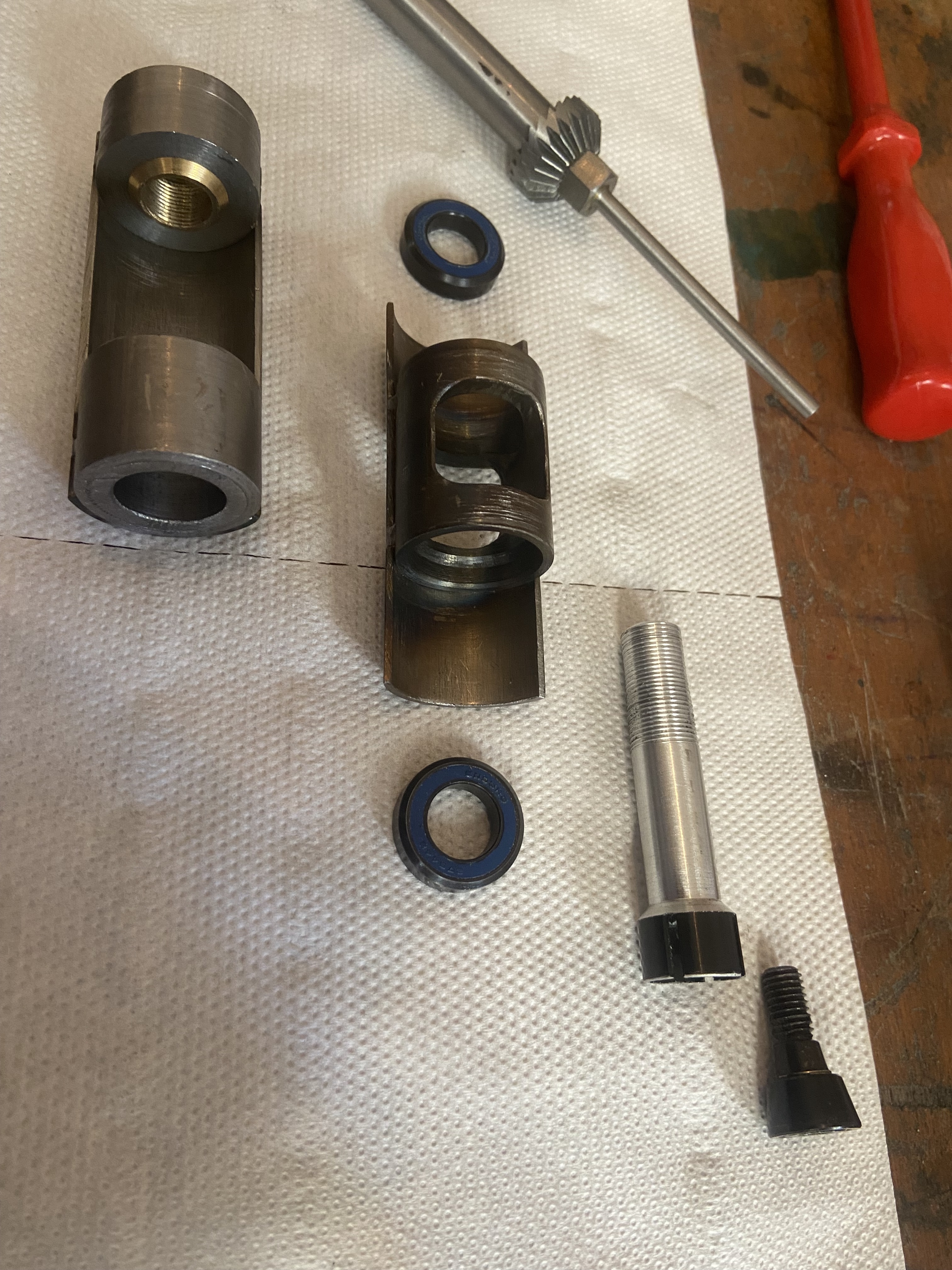
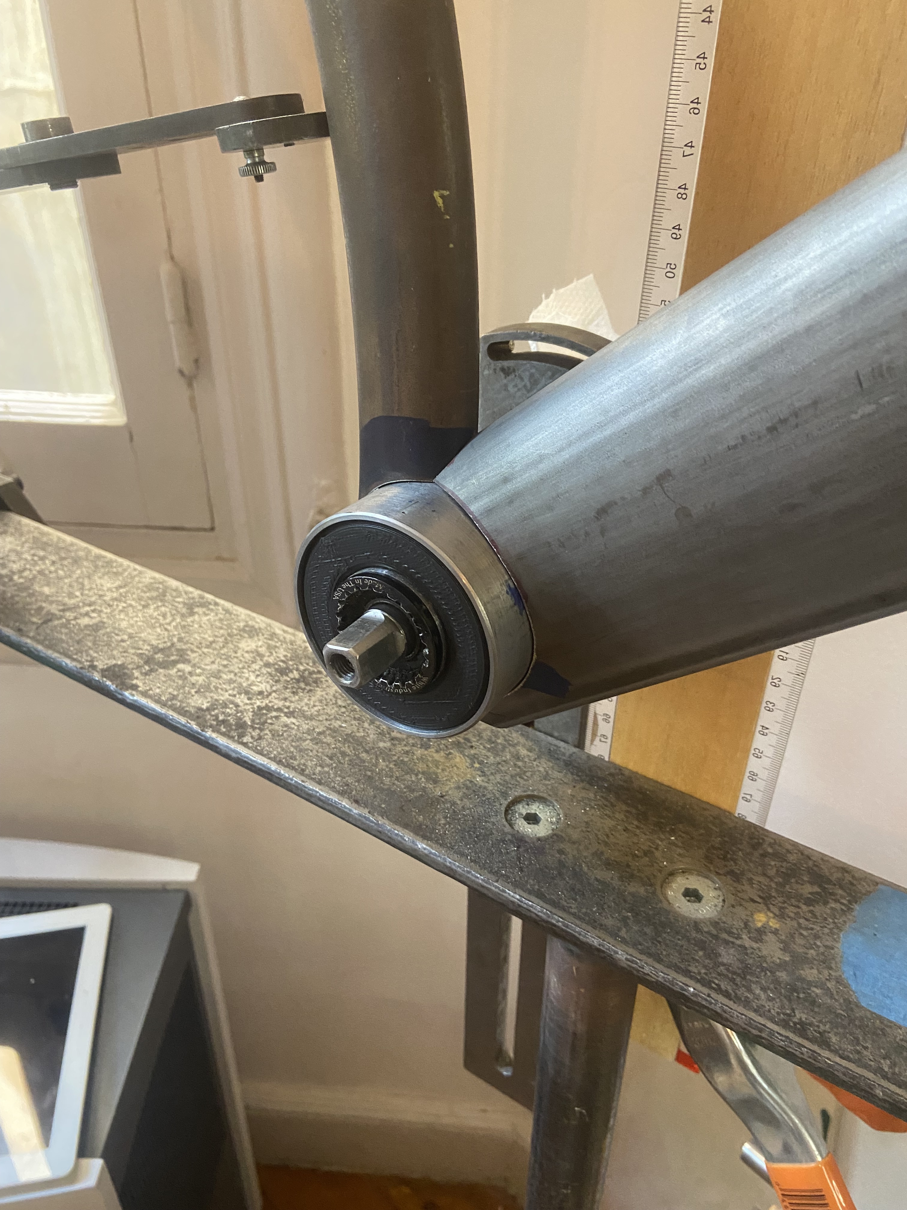
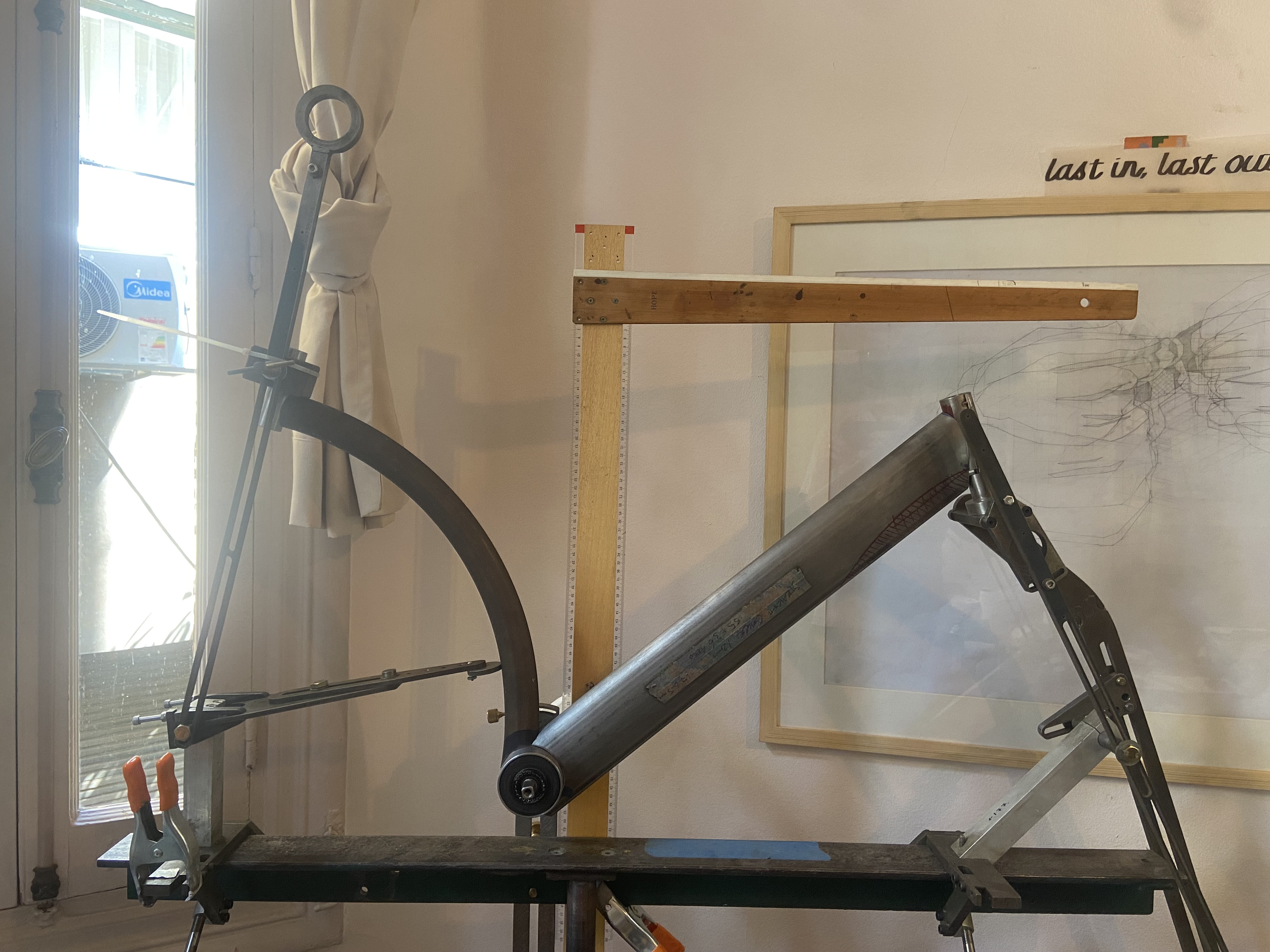
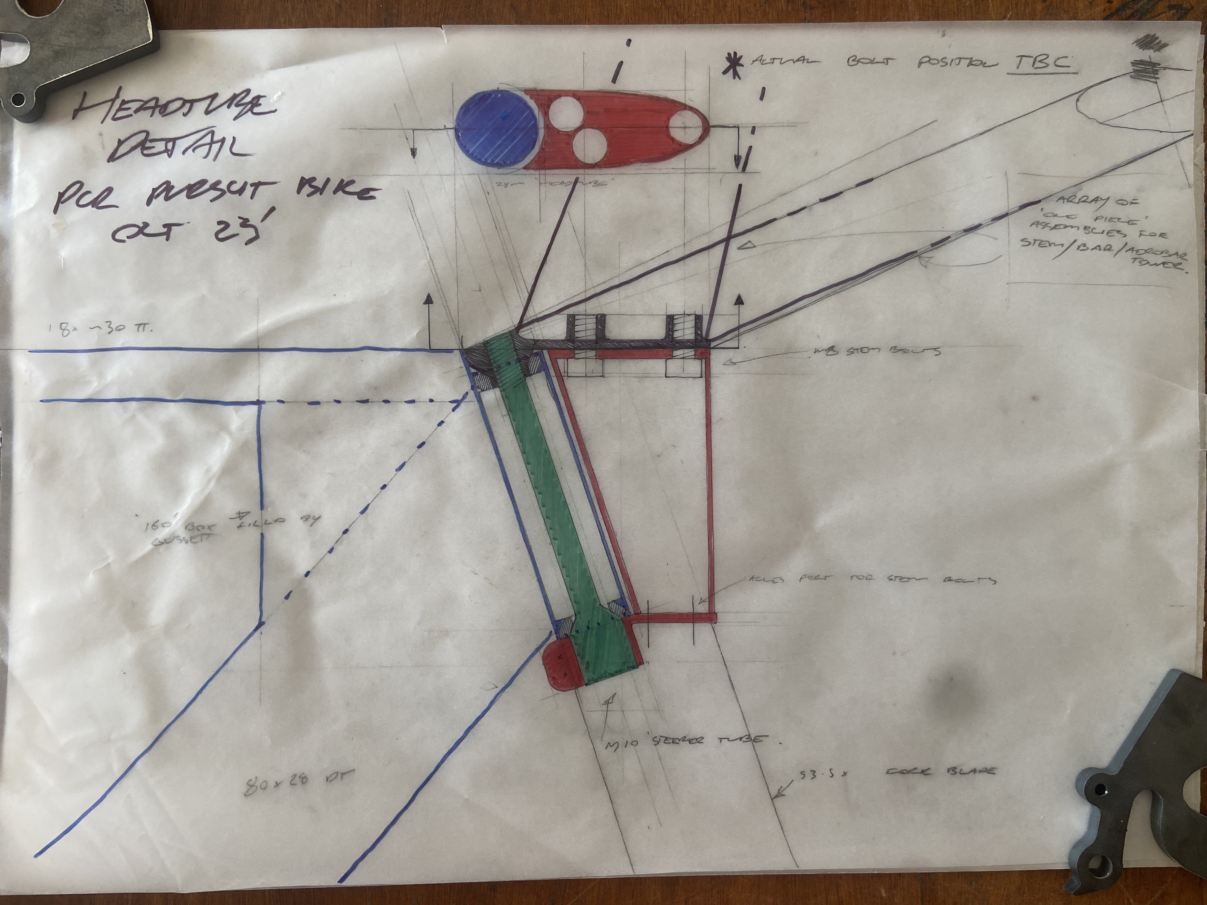
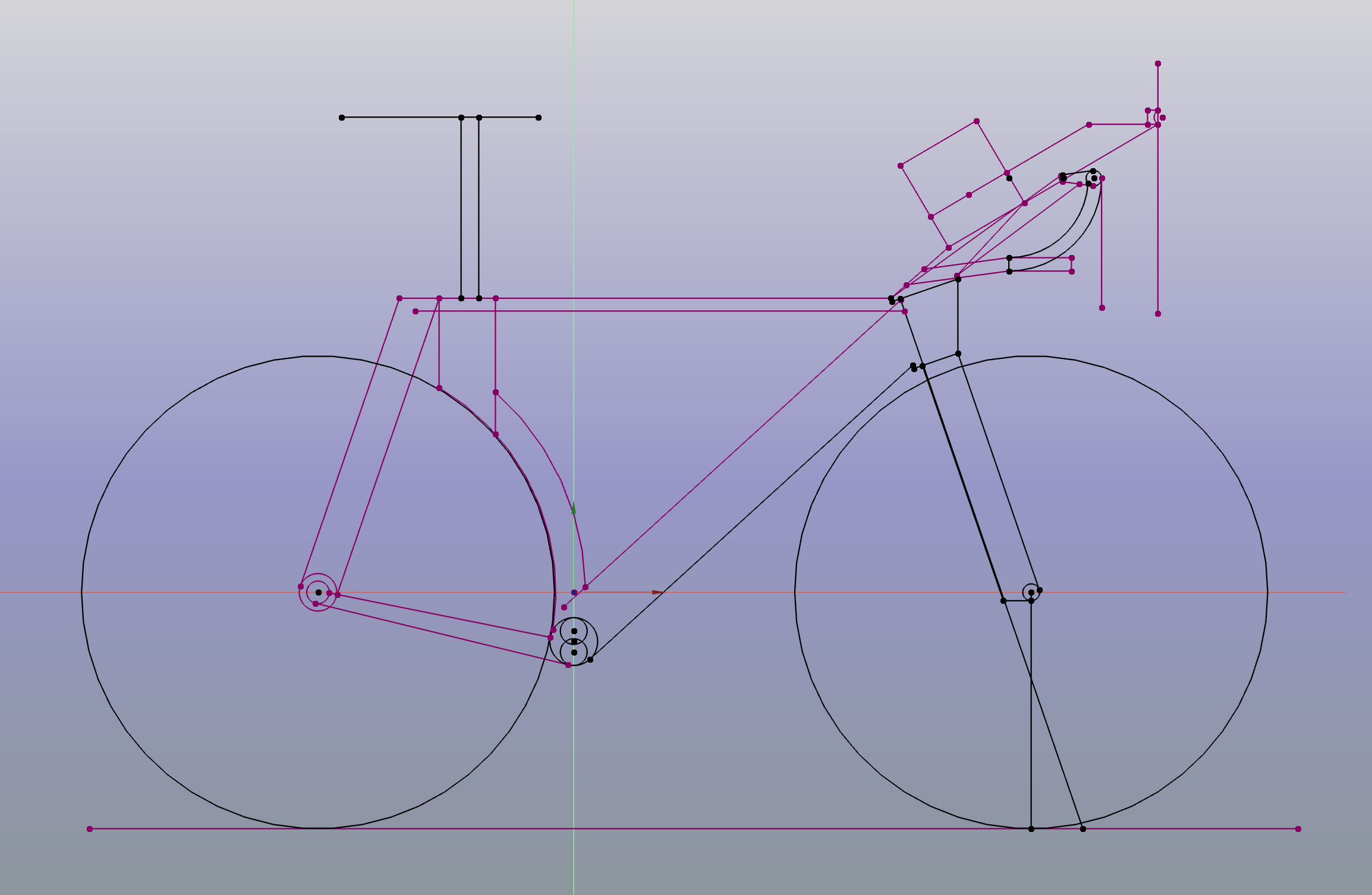
I’d like to build a very narrow hinge-fork style front end using some very small headset bearings from enduro. my current design has it sitting at ~28mm head-tube width. i’ve attached a couple of draft drawings.

in this design the stem would form a critical part of the headset assembly, and bolt directly to the fork, (which extends upwards infront of the head tube,) with a ~10mm bolt-esque “steerer tube” being added through the head tube from the bottom, and secured with a couple of pinch bolts as the last step of assembly.

I think this means integrated/proprietary handlebar, and im keen for that, or at least the base-bar ( given a potential need for adjustability to meet bb/cranks changes and other fitting requirements having aerobar options might be good,) with potential for a one piece mass-start or sprint front end being fittable, though this isn’t really a priority. I have another track bike I’ll do those races on.

the baby elephant in the room

this bike isn’t going to be uci legal and that’s OK.

while bike-NZ operates under uci rules, our local track racing club, like I imagine many clubs that aren’t basically pro-teams, operate on a more casual basis, something along the lines of “is this providing an unfair advantage or creating an unsafe scenario” seems to be the modus operandi observed by our organisers, im not the only one making stuff and this really helps harbour innovation and engagement-with-making-stuff at our club, which is pretty cool.

I do need to fit inside uci rulings around position, and while blatant disregard for the intent of the rules to try and gain an advantage is neither where id like to lead our club environment, nor likely to be looked on kindly by my peers or the commissaires, breaking design rules because it makes the seat tube damn cool and also I had a handful of the curved tubes rolled before I learned about a design rule change, that’ll be ok…

road tt’s are a totally lawless environment, triathlons even more so no worries there.

if I end up getting DQ’d racing somewhere else, well that’ll be a shame but ill suffer it.

that’s a mammoth, thanks for reading, I welcome your thoughts.

3 Likes

writing that all down obviously helped me get my thoughts in order.

after quick rummage and a simple parting job, it turns out I have the road axle for the 182 hub in hand.

it came out of an old 404 I had kicking around for a rainy day, and simply needed the centre-facing end of the NDS locknut/endcap trimmed to length. the free hub body is a bit chewed up but I imagine I can replace that easily if it causes issues down the track. .

making a 5mm spacer that fits under each OLD for the track axle wont be difficult, that’s one problem solved.

1 Like

Cool project. I’ve done the geared/singlespeed conversion with AXS, it’s a piece of cake except for the supposedly non-reusable quick links. Hopefully you’ll be able to hide the blipbox and cables inside the basebar/stem, then all you’ll see are the buttons on the ends of the extensions. I have a Cervelo S5 set up as a TT bike/road bike/fixed gear using a White Industries eccentric hub (which didn’t work very well because of the tight seat tube profile).

Re EBB, I’d be concerned about how it will affect your position and how much time you’ll spend adjusting everything back and forth. Perhaps you could use an index or reference mark on the EBB so you can fit it at known repeatable positions (to give you a known BB height) and then just tweak position in a pre-determined way to match? Ideally you’d have a BB shell that is a slot rather than a round hole, so you could slide the BB up and down rather than eccentrically, but engineering this may be more trouble than it’s worth. Or perhaps two BB shells stacked one on top of the other?!

Re brakes, an external cable with slotted stops is by far the easiest way to do what you’re aiming for, but obviously very un-aero. If you do go with internal cables I’d suggest a full-length outer with a full-length internal guide tube, so you can just undo the cable from the caliper and pull the whole thing out, then feed it straight back in again without any messing around. You could possibly put a little channel under the base bar for the cable to run in, with some clips or tape to hold it in place.

1 Like

thanks for the reply reply Joe, cables in channels is a great idea and one I hadn’t thought of, it seems like an obvious solution that I might be able to apply in a few places. ill brew on it.

Im also a bit concerned about the ebb being a lot of Pfaff. crank length is an area id like to explore more, but I do feel like it could start to take away from my enjoyment of the bike, MOST of the time, ill be riding short events on the track on shorter cranks and long events on the road on longer cranks, so Its not a completely stupid idea to simply adopt a compromise, im just not quite ready to do so.

the up/down bb “slot” has crossed my mind, but puling that off here in Cairo feels like a bit more trouble than id like to take on… though a double eccentric mechanism has crossed my mind (I applaud anyone still reading after I write that) … I haven’t put any thought into figuring out the mechanism because at face value it feels overly complex, indicators or reference marks would be a must, but I suppose the ultimate adjustability could be X/Y independent…

I suppose too there are other potential mechanisms for adjusting BB height, I’ll keep sketching until some tubing arrives.

Fun project! I have done a few builds with some similar elements, that might provide useful inspiration:

  • IP/Fixed TT bike:
    John’s TT/Pursuit frameset | English Cycles

  • Obree replica with custom EBB; super narrow cranks mean BB height can be very low, even when running fixed gear on the road (I added a TriRig front brake, running bare cable straight up and into the stem):
    Obree tribute pursuit bike | English Cycles

  • TT bike - ‘headtube’ is only 18mm wide, somewhat similar design to yours, but the bearings are in the crown and stem, secured with bolts from underneath (so no external fasteners). There is a built in internal steering stop so that the bayonet part of the fork can’t run into the side of the frame:
    Time Trial Mk2 | English Cycles

Looking forward to seeing your build come together.
Rob.

5 Likes

I love track bikes on the track. The sport is so pure and precise.

There is some really cool track stuff going on that does not get enough coverage. I can’t wait to see the 2024 olympic bikes.

This frame seems similar to what you are trying to achieve:

It is a mix of 3D-printed parts and extruded tubing:

To me, the hardest parts appear to be the fork’s “bulkhead” and the curved seat tube.

  • I think the fork bulkhead could be 3D printed quite easily and solve some problems
  • the curved ST might be a good candidate for carbon fiber construction.
1 Like

yeah track bikes are awesome, the context of use is so narrow that design decision can be prioritised for VERY specific outcomes, it can lead to some absolutely wild bikes; the build I’m currently finishing-off is a bike for a very compeditive sprinter, specifically to do flying 200’s on two specific velodromes, we’ve had great fun testing all sorts of limitations and pushing our design to meet them, knowing it won’t be used outside this context.

Hah! hi Rob, thanks for chiming in, Ive spent a LOT of time looking at your bikes over the years, (a couple made it to NZ, but mostly on your website) especially the curlier TT designs you’ve published. the bikes you’ve linked all definitely serve as inspiration. does the O’Bree EBB (OBEBB?) function well? in my world, standing starts on a track bike and EBB’s are un-tested… though iim not sure standing starts with that handlebar position are /all/ that explosive.

T red are definitely someone I also follow closely (alongside mr English above ) and often look to for inspiration. I know /that/ bike has been a little divisive among some, but it definitely speaks to me, I REALLY like their [mass start bikes too]. (Argentina's new track bike could be the wildest one yet | Cyclingnews)

they do seem to stick to having a steerer tube, which I can understand. and while I don’t have any data suggesting that its worth getting narrower than that encourages, I still believe it is.

curved seat tube is reasonably simple to construct from thin wall tubing, I’ve built two, and have rolled material for a few more.

my first one (D shaped profile) is being ridden by [@herrnick] (https://www.instagram.com/herrnick/) and is visible on his instagram there ( hint: its the green one) . it uses a piece of 1.2mm 4130 roll-formed into an oval and then section rolled to diameter, before being cut in “half” and the rear surface capped with a strip of 0.9mm sheet metal and seam welded.

me second one is on my current personal track bike and is a much simpler oval profile (again roll-formed, this time from a 0.9mm wall tube) and section rolled to diameter.

The roll forming and section rolling was completed to spec by the wizards at Woodbridge industries in Lower Hutt

i’ve done a handful of stub seat posts of both external pinch bolt and internal pinch bolt designs. but I think this frame likely needs more saddle-height adjustment than is really practical for either and ill stick to a normal (~ish :wink:) seat post of some kind…

the fork “bulkhead”, as you identify, has definitely been a bit of a sticking point, though admittedly I do feel like i’ve come to a workable solution with the drawing above. (front brake hole not included, though i’ve got an idea on how to fit it in unobtrusively. I have figured out an order of operations for assembling /that/ design which i’m satisfied with and tooled up for, all the steel is quite simple to aquire and the lathe setups are all pretty normal.

I did sketch /quite/ a few iterations of fork/headset/headtube/stem assembly, including some designs where I was thinking about more extensive machining or 3d printing but I didn’t come up with any which I felt were genuinely /better/ and I think this is mostly because i’m struggling to trust the material; I’m unfamiliar with it and this is a high-risk part.

I messed around with lots of 3d printing at uni, it was a big buzzword in the design-sphere I was in at the time an my university had a huge focus on adopting anything and everything 3d printing it could, and making it as accessible to us as possible. this included a small amount of designing for metal printing (SLS) which was quite expensive at the time. Its possibly quite a different process now, its definitely cheaper. but I worry about aspects of the materiality (strength, fatigue life, failure mode etc) that basically all come down to “I don’t trust my feel for this because I haven’t got any depth of experience with it in this context” which is turning me off using it for a fork crown on a racing bike.

that being said.

I’m very interested, if a little wary; I admire your application of it.

I’d like to say im looking for avenues to develop more familiarity with the materials and processes because I think (as your and others here work has shown) it opens up design opportunities that are otherwise pretty inaccessible to the custom-bike-frame world.

So I think I should print some other parts for this frame. dip my toe in, so to speak

front and rear dropouts and a rear brake bridge come to mind as parts i’d otherwise be making from scratch. also binder bosses, maybe the seat stay-seat tube junction? maybe aerobar bits ( there’s always lots of bits :roll_eyes:) … but its clear to me i’m not ready for a fork crown…

as for the BB ( said in my best “and now for something completely different” voice)

the double-eccentric idea has grown on me; Im thinking I can make a singe eccentric sleeve, something which can flex open, like this

and install a stock Bushnell BB into it, giving me a system that looks something like this.

ill need to machine some markings to aid setup, but that’ll give me ~28.6mm vertical-only adjustability inside a 68mm ID BB shell, if i’m careful. I think for a first attempt, ~28.6mm is a compromise im happy with, something like 46-74mm range in bb drop will give me room to breathe.

edit: now that I look at it, I might have more luck machining those slots from the outside.

a test run of the front-half of the fairing-tube.

it feels promising; it is 1.2mm wall 4130, ill either use this material for the real thing, or use this actual part, it’s a little short as I made it from an off-cut, but I can potentially shrink the head tube dimension, given that precise head tube length doesn’t actually /really/ matter in this case.

apologies for all the edits, I typed that too fast.

1 Like

Great work! I didn’t think of ovalizing it first, and then rolling again to curve it. Do you happen to have any photos of the machine and dies they used to ovalize the tubes? Off-the-shelf oval tubes are hard to come by. It would be great to have a consistent process.

1 Like

I don’t have any photo’s of the process, though i’ve seen it happen, it’s about as simple as you can imagine; a bunch of profiled rollers that the tube gets dragged through incrementally. he goes slow on thin wall stuff, so it takes quite a few passes, with adjustment in-between, but nothing magical.
Section rolling is again simple, he had profiled dies for the specific oval shape ( it’s a shape he produces oval handrail bends in) and he worked back and forth to sneak up on the required radius.

However, the machines are big heavy freestanding ones, not the kind of thing i’ve got scope to bring in house until im back in NZ and in a real workshop. if I visit the tube mill when i’m back in NZ this (NZ)summer, ill get some video/photos.

there’s been a small hiatus, while I took a holiday and did some work on a frame for a friend; excuse the uncut headtube.

in “two-birds” news. the 55mmx13.5 mm aerofoil tubing from performance metals in the UK has been picked up and should arrive here within a week or two. im thinking this will serve as fork blades and chain stays.

and today THE CUTEST headset bearings ever arrived.

next I need to find some stock to make the fork-crown-plate, and the steerer bolt, and the interface plates for the bulkhead/stem assembly. then I can mock up a headtube assembly.

i’ve put in an order for a Bushnell BB, and I have some aluminium stock to make the eccentric “doubler” sleeve. but ill wait until the Bushnell unit is actually in hand and take some measurements before moving forward. the bb might take quite a while to make its way here…

I may need to find a ~68mm reaming tool. (aswell as pre-machine a shell, and likely also a heat sink , because yikes,) but I want final dimensions and to have the bushnell unit in hand before finalising any of these dimensions.

I’m optimistic that finding a cheap enough (read dirty, blunt and old) adjustable reamer in this size shouldn’t be impossible, Gomhoreya street in Cairo seems to have a real soft spot for junky old European machine tools and accessories in utterly bonkers sizes, especially ones in bad states of repair… and anyway if I can’t, I can always just line bore the “bb tube”…(continues laughing maniacally)

2 Likes

I managed to make a bit of progress on the head tube/crown mockup assembly before having to start packing up my workshop (off on holiday and then moving house immediately upon return).

“steerer” with bearing installed;

( note the upper bearing seat riding on the M10 threads is part of the “stem”.

this was turned from an M16 bolt, I cut the upper threads with a die, and the old adage “single-point them you idiot” rang true as always… (the die wandered a little), probably be OK but anyway its a mockup for a reason and as i discovered later, i’m definitely thinking about making some changes.

with that done, turning up a simple head tube was easy, and fabricating a “crown plate” was one hole and a weld away, so I pressed on and tacked on the back surface of the bayonet tube and soldered a pinch bolt where id be able to get access to it once fork blades were installed.

im reasonably happy with the way this assembly comes together, and doing a mockup has forced me to think about dimensions a little, it feels seriously small in frontal profile which i’m especially happy about, and in situ, the “steerer clamp collar” will have much less visual presence than I was worried it might, which is great.


.
also, fork blade stock arrived! big shout out to frank (if you’re following this) for picking them up on a recent visit to the UK and lugging them around Europe on your holiday.

I anticipate using this stock for seat stays aswell, and potentially the upper seat tube.

I have a couple of current concerns;

im a little worried about the fork blades basically being butt-welded onto that crown plate, I think they’ll almost definitely be fine, but I don’t see it as ideal; and so im wondering if I should re-design this join; my first thought is if I should bend the sides of the plate down to provide a longer weld and move the join out of a plane that’s almost perpendicular to the tube.

im also not in love with the pinch bolt arrangement as it stands.

seeing this in the flesh, I think a better design would be a solid crown plate, with no split at the back, which is a tight fit on the “steerer bolt” ( it /could/ be tight enough to basically be pulled into place by the thread) , attached to the bottom of this crown would be a collar which could cinch onto the bolt head, it could again be a very tight tolerance and operate more like a seat tube slot, rather than a seat collar. I imagine a vertical slot as usual with a horizontal slot around maybe 1/3rd of the join, allowing a bit more movement in the face of the colllar closest to the pinch bolt.

I was trying to keep the stack height of the collar as low as practical, but seeing how it will work and look in 1:1 I have no problem increasing it.

currently the crown tries to change shape a little when I do the pinch bolt up tight, which I don’t think is the best solution here.

there will likely be no practical updates here for a couple of months as i’ll be without workshop access, but expect thread-necromancy around march.

till then, does anyone have any thoughts on different ways I could retain the steerer bolt?

2 Likes

also, im thinking of punching a ~12mm hole hole straight through that bayonet tube, and brazing in a machined insert to accept a front single-bolt-mount rim brake. (ill need to take the fork off the bike to install the rear nut, but I think that’s tolerable, given I should probably be keeping an eye on those tiny headset bearing ATLEAT twice a year anyway…

I imagine I’ll do this process last, mostly so as to be able to work in descending heat-order, but also I can align the insert with a jig referencing the axle once the forkblades and dropouts are completed.

I’ll have to do some sneaking to still allow Allen key access through the bottom of the crown to work on the internal “stem bolts” .

Nice progress!

Is it possible to do a bi-plane style fork?

Or were you planning on the “double crown” style?

I am having trouble visualizing what you are describing, but I do have a concern over the current design. For clamps to work, they need some room to flex. As is, you have ~5mm of material that is flexing. I think it’s very likely that the pinch bolt is not transferring the clamping force to your steerer because it is too stiff.

I think you are describing it correctly, you need some sort of long slot to allow the clamp to flex, like a seat tube clamp.

Usually, when I am trying to figure out a bearing-clamp-axle assembly, I do a bunch of quick 2d sketches on paper to help me visualize what is going on.

3 Likes

thanks for keeping the conversation rolling.

here’s a more clear example of what I mean about the fork crown plate slot.

NB: the current arrangement is the sketch on the right, my new proposition is on the left.

the current situation clamps the steer-bolt-head in the way a traditional stem clamps a traditional steerer tube; the entire part deforms around the tube.

I’m proposing something more akin to how a traditional seat tube clamps a seat post in the hope that it will help preserve the geometry of the “crown-plate”; I don’t want the axle-steerer relationship to change when I do up the pinch bolt…

as for the crown-to-blades-join, I did also think about a bi plane option, I could potentially add a second plate “below” the binder-sleeve, attaching both blades together, aswell as to the bottom edge of the sleeve/ binder;

something like this, either with, or without the ‘bent down’ crown.

excuse the biros on graph paper, nice drawing tools are packed already…

4 Likes

its been quite a break on this one, but im back home from a summer of racing and after some time away I think i’ve solved my split-crown, and steerer-bolt retaining problems.

while away, one of my tasks was clear out a few old parts I was storing at my parents house, which included a yeti SB5.5 frame I’d been sitting on. all of its pivot bolts use a clever expanding collet design. the pivot bolt head is round, with a couple of slots in it. slips into a round hole, does up with a large Allen key ( ~8mm) and then a small ~M4 Bolt does up into the bolthead, with a tapered sleeve on it which expands the bolt head and keeps it captive in the hole.

Screenshot 2024-03-12 at 12.09.39 PM

im thinking this arrangement could work well in a vertical orientation, if I move to a solid crown, and keep that tolerance really tightbetween the bolt head and the crown-hole, which is something i’ve been thinking about for a little while. a simple u shaped, wishbone-style, very thick piece of steel, that can receive the steerer bolt from below, attach to the fork blades and attach to the front bulkhead/fairing.

doesn’t need to be light, making a second one using some 3d printing or more extensive machining is an easy upgrade for MkII.

anyway, I havent really got my workshop setup in my new space, nor done any drawing, but a small update to say i’m back, and changing tack a little bit.

expect a proper drawing of this arrangement within a couple of weeks, and all going well, some machined parts shortly after that.

2 Likes

well, last week was a flurry but I did find time to sit down and get my (baby) teeth into some fusion 360 basics; id been being a stubborn curmudgeon about solid works for about a decade so it was well overdue; I still have some reservations, but that’s another discussion; here’s the fork crown/steerer as it exists in my mind; headtube is see-through

here’s a section view of the assembly as modelled.
{notes read:

(upper) brake and tool access holes not finalised,

(lower) green fill not visible and apparent step in collet mating surface due only to section view, no step present in part.}

im not 100% about this, and my lathe is still being re-assembeled in the new workshop, so I have another week to mull it over before I need to start making chips.

a few ongoing thoughts;

I’m imagining slip-fit internal langs with fork blades silver soldered on (45%), OR tight, press fit tangs with a V ground and TIG weld around each blade; i’d value some opinions here from fork-makers

To make that fork crown, I am planning on manually tuning an aero-donut, then cutting it up, and hand filing the profiles to slot into the fork blades; that solid fork crown is going to weigh ~460g. Thus I could 3d print this as a shell, which would take a few hundred grams out of it (depending on wall thickness) and open up easy possibilities for longer tangs than I would get from the “aero-nut”. BUT I have to find a reliable way of shipping that print to cairo egypt. so Im thinking Ill leave it for now and explore printing for Mk2; if I finish the fork and don’t like the weight. I probably won’t care about the weight, and as stated earlier, maybe fork crowns aren’t the best place to start with 3d printing…

i’m thinking about a threaded hole for a front brake, and a carefully ‘depthed’ washer, so a front brake screws straight into he fork, and arrives at a serviceable torque as it arrives centred, but im aware thread are great stress risers, so a small brake nut ( i.e. like a standard rear-brake ) I can get in from the back through the tool access hole is also on my mind, though machining the counterbore for it will be SUPER fun.

im ALSO (finally) thinking, having that collet entirely contained within the crown would be better than not, so now that I see it, giving it a small surround to completely enclose it would be best, I could likely leave the internal, “back half” of the surface of the aero- donut square, and finish it out by hand, leaving a bit more more meat around the “steerer-hole”

1 Like

a bit of material left surrounding the steerer bolt head could look something like this;

2 Likes