ok so I have a set of working cranks, and I said id post some drawings, so here they are.
there’s a bunch of numbers here which I know break a few best-practice “rules” (e.g. are more precise than I can reliably measure, and or, are averages with more decimal places than the data they came from).
this is a first attempt, its my best first shot; ive lightly ridden the cranks and haven’t had any problems, im feeling as confident as I need to, to give them a good nudge when I next get a chance to get on the track.
I have done my best to very that what was machined is what was drawn, and as far as my tools are confirmed, are all well within 0.05mm.
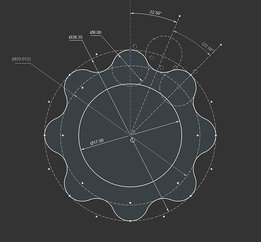
this is the end of the SPINDLE.
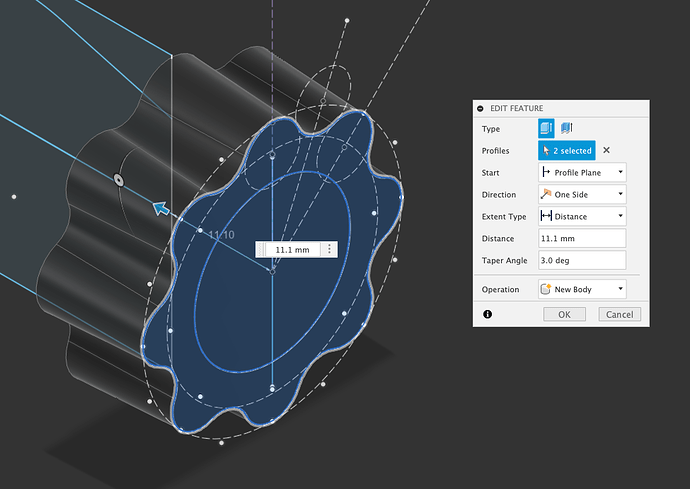
the used part of the splines ON THE SPINDLE are formed by extruding this 11.1mm, at 3 degrees.
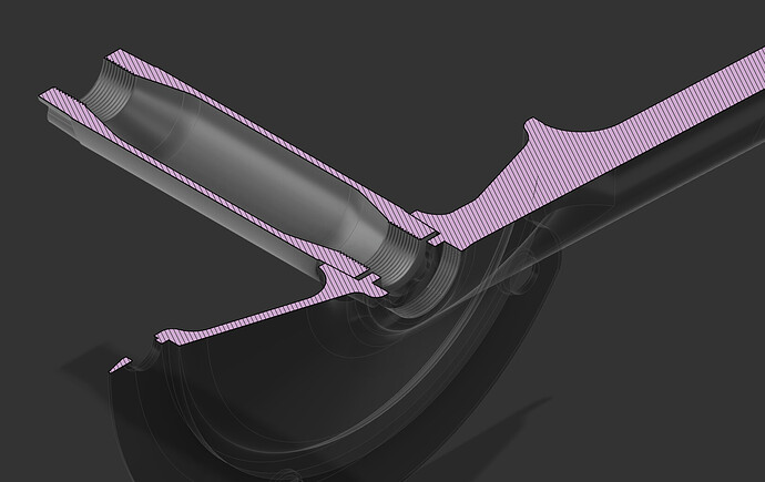
the splines in the cranks are the same profile, they are also 11.1mm long, but they extrude 1.526mm IN THE OTHER DIRECTION. this leaves a gap, which closes when the crank bolt is done up.
interested in building cranks? want files? im happy to share, please hit me up.


