Yes, there are existing off-the-shelf parts for basically everything you need for an 8020 frame jig. There is no need to do any laser cutting/cnc/3d printing.
Seriously, this has been hashed out multiple times on multiple forums and there have to be hundreds of examples on the interwebs by now.
The really useful thing at this point would be to identify the “best” designs and really flesh out the details of putting one together (Instructables style) so that the signal/noise ratio is a little better and people can spend less time digging through bad designs or unclear instructions.
Worth noting, there’s also the SKYNET fixture. I’m biased towards that one, obviously.
It was designed around using simple manual machining to create all of the parts. It really just depends on how accurate, and how much capability you want in your fixture system. The WOPR just builds on the concept further, replacing more physical complexity with clever math.
You can make really nice bikes with a much simpler jig (That’s what I did for a few of mine) But there’s a lot of drawbacks, obviously.
There’s also a friend of mine near me that’s currently building his SKYNET, making use of a MDF board to put it on, since the welding table is the real expense. Everything else can be quite cheap if you shop around (or already have some of the hardware available)
If you have access to a makerspace (or just someone with a CNC router or laser the MDF is a great option.
Yep I’m here! I just finished up the Skynet on MDF board. Good thing about it is if I do invest in a 2x2 hole grid welding table, the jig should easily transfer over from the MDF.
I’m out of town right now, but will post some pictures when I get back.
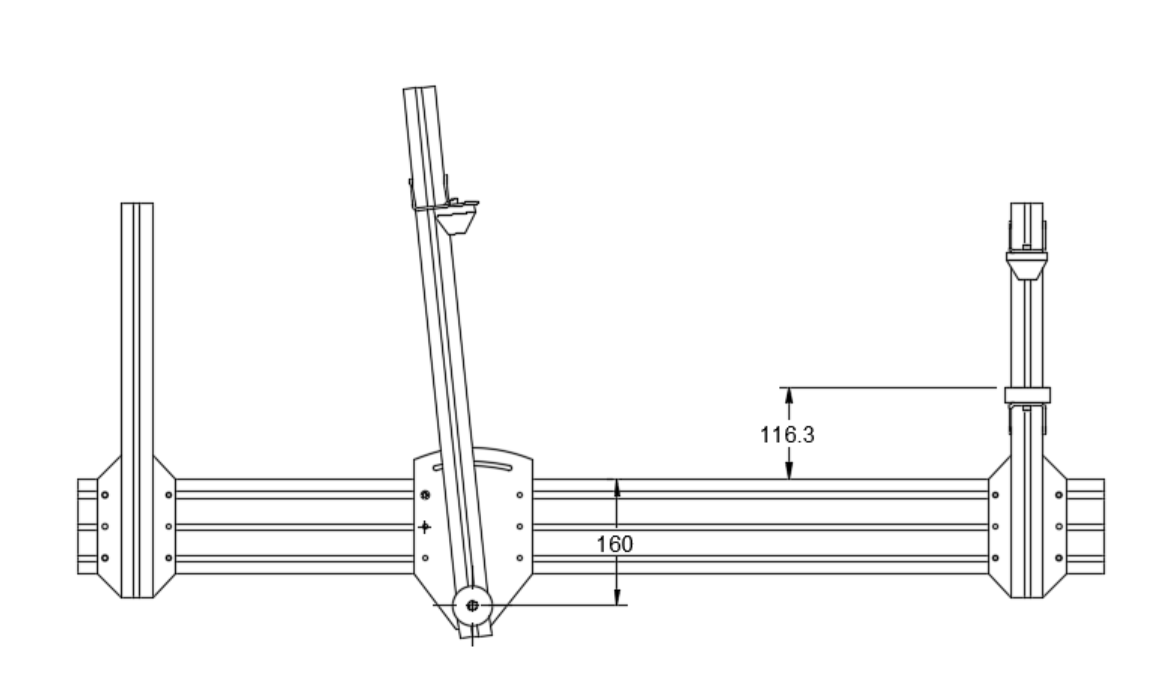
Only comment I have at this point is to probably do a taller centerline off the table surface. The Skynet is 160mm but I ended up at 157mm getting everything aligned.
I still haven’t put any tubes in the jig yet because I’m also in the process of building a CS / SS mitering jig with the leftover 80/20 I have from building the SkYNET.
The costs for the SKYNET is probably in the $1500-$2000 dollar range but you are inevitably going to have screw ups, shipping costs, etc. This also doesn’t include tool costs, the biggest of which is a milling machine and lathe. Luckily I am a member of a maker space that has a milling machine and lathe.
Time is also a huge investment. My guess is that it took me somewhere in the range of 200-250 hours to make the SKYNET. But I had literally zero machining experience coming into it. Also the machines in the maker space do not have DROs. Having a DRO on the milling machine probably would have saved me 50 hours in set up and do-over time.
That being said, the SKYNET is a great option if you want something intermediate and have the tools and time to get it together. Also the drawings for it are available for free from PVD. Thanks PVD!
As someone who builds about one frame a year I have stayed away from making a jig. I build one joint at a time and use small simple fixtures to hold the pieces where I need them. For example, tube blocks clamped to a long piece of square tubing.
One more small nitpick: holding tubes using cones means you have to have a perfect cut. Seems like a good way to introduce some misalignment if you don’t have a lathe to cut the tubes with.
Thanks for the ideas and feedback everyone. A lot of good ideas and callouts to existing solutions.
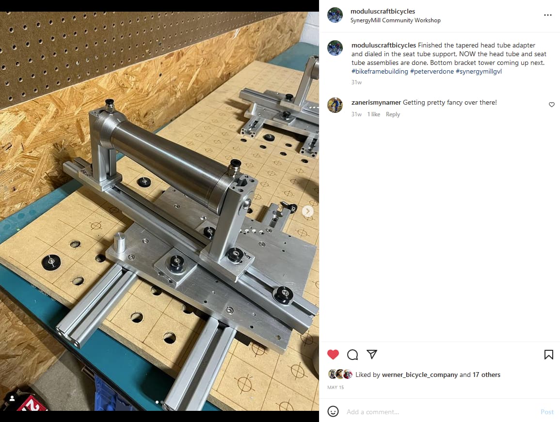
@Modulus-Dave I think your fixture build is more impressive than a frame build! Very cool.
@ben.land101 and @Modulus-Dave what is the process of tacking/welding your frames with the fixture? Do you have adequate access to the other side?
I created a Pugh chart to help organize the discussion. To be clear, these are subjective rankings. The lowest score does not mean it’s the best choice, some parameters may carry more or less weight than different people.
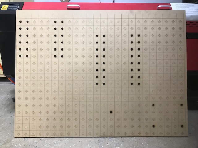
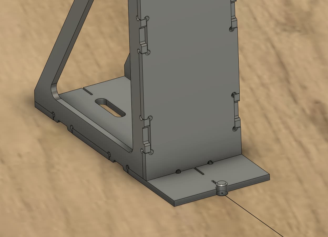
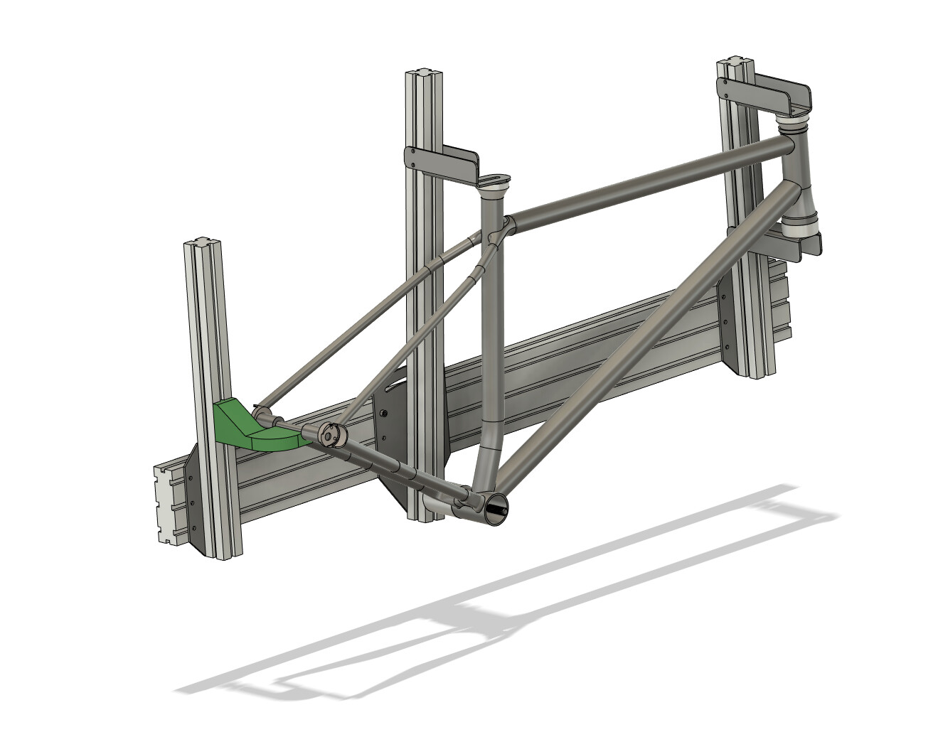
I took people’s suggestions and examples of the MDF board, and realize that it is a much better fit for this project than the welding table. Using the MDF as a sacrificial fixture is both fast and cost effective ($60 at homedepot).
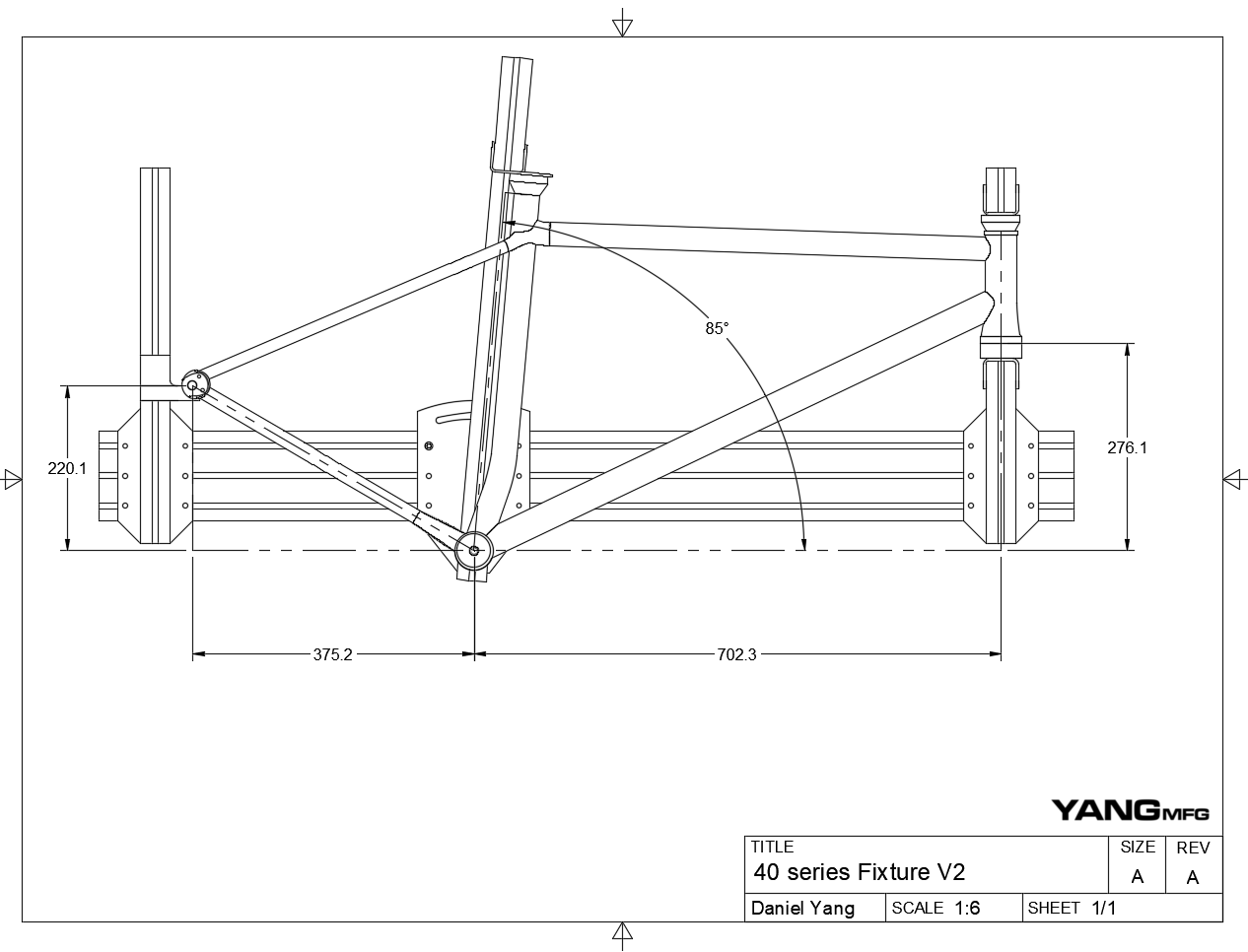
I bumped the table to center-plane distance to 150mm to give more welding access at the cost of some material cost
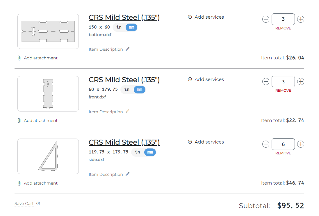
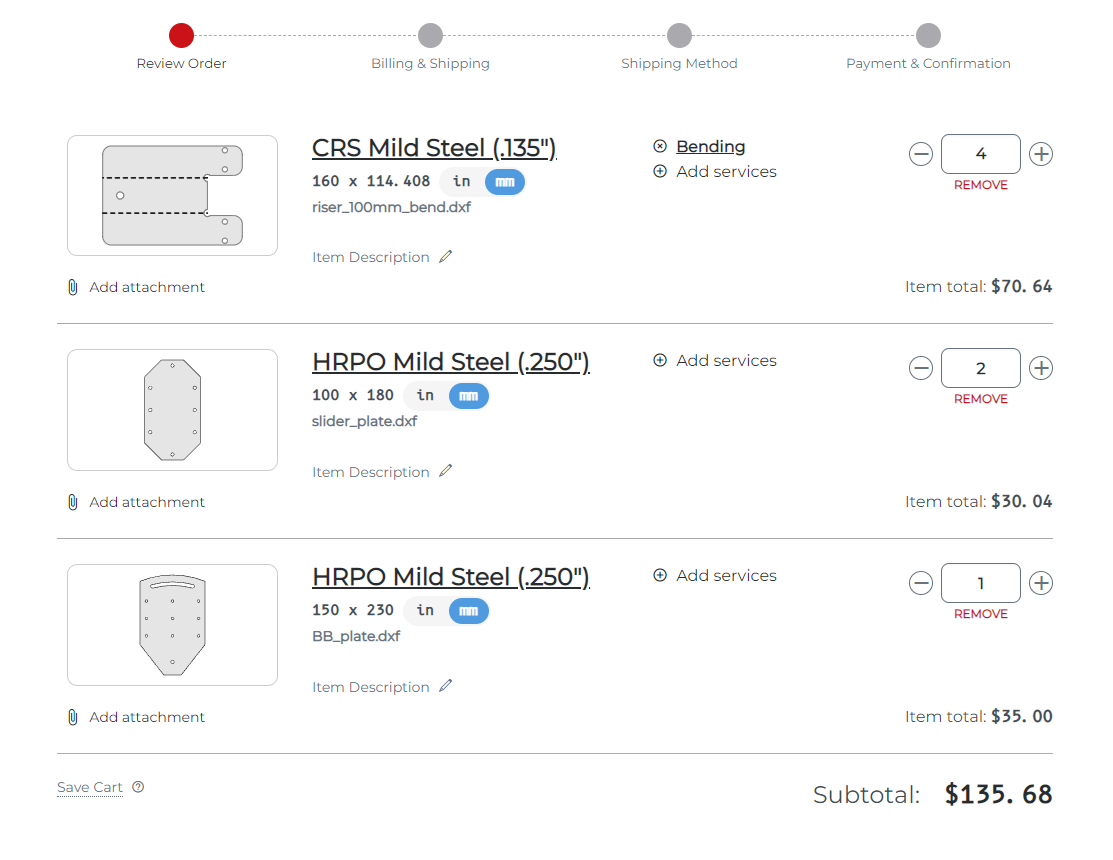
BOM:
Item
Cost
Qty
Sub
Laser Cut Fixtures
$35
3
$105
MDF
$60
1
$60
Paragon Dummy Axle
$75
1
$75
Aluminum Pucks
$40
4
$160
Misc hardware
$20
1
$20
Total
$420
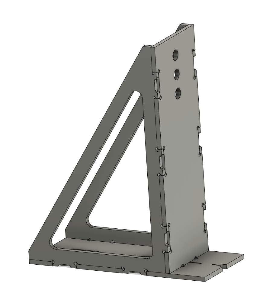
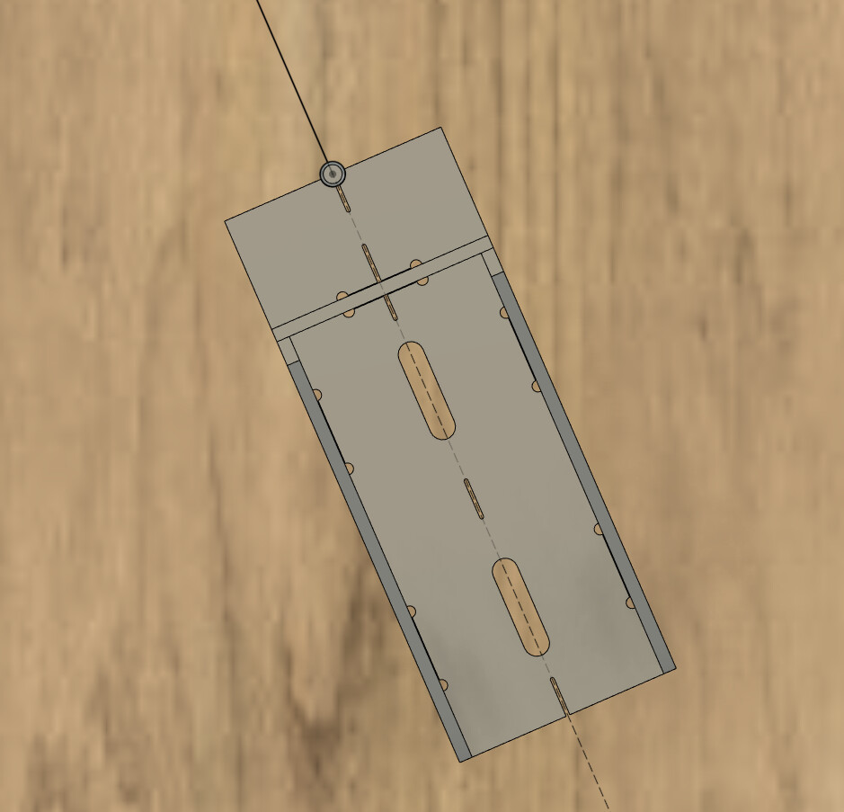
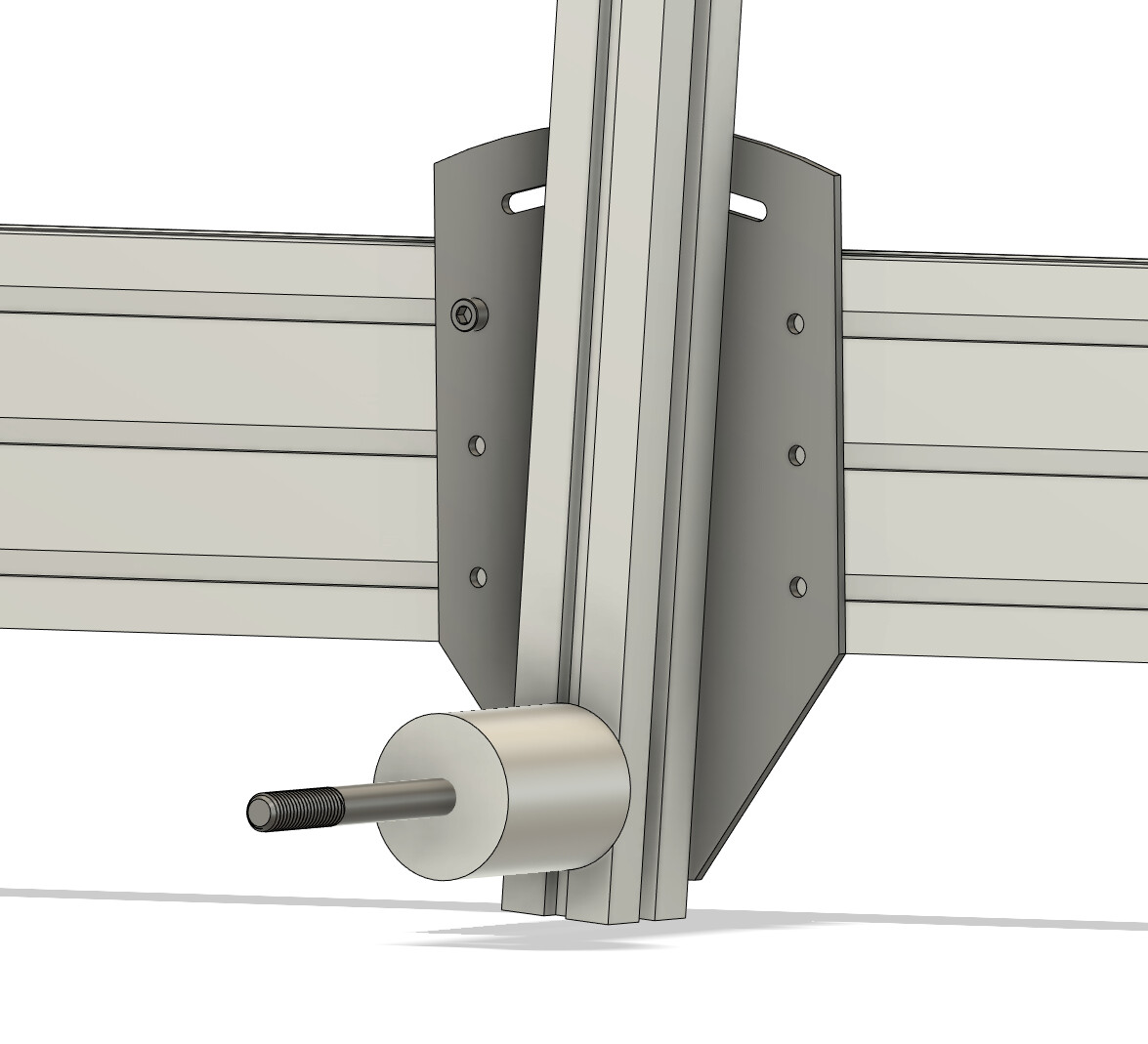
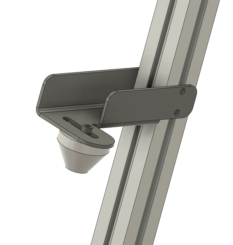
Laser cut fixtures:
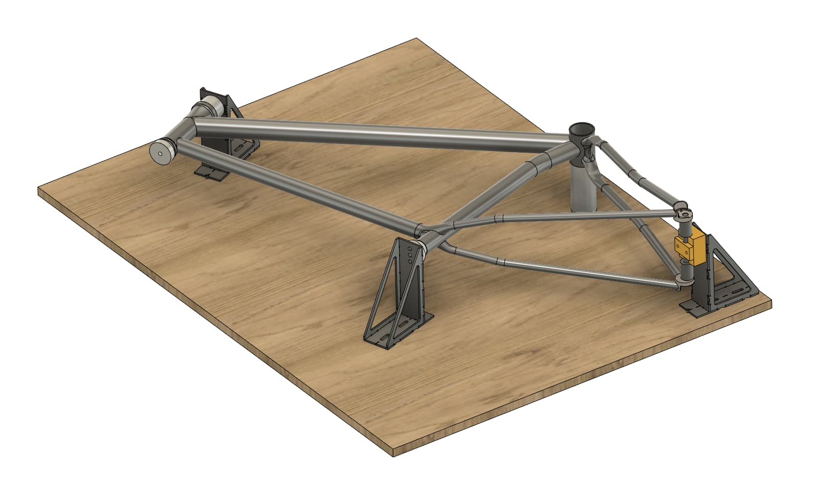
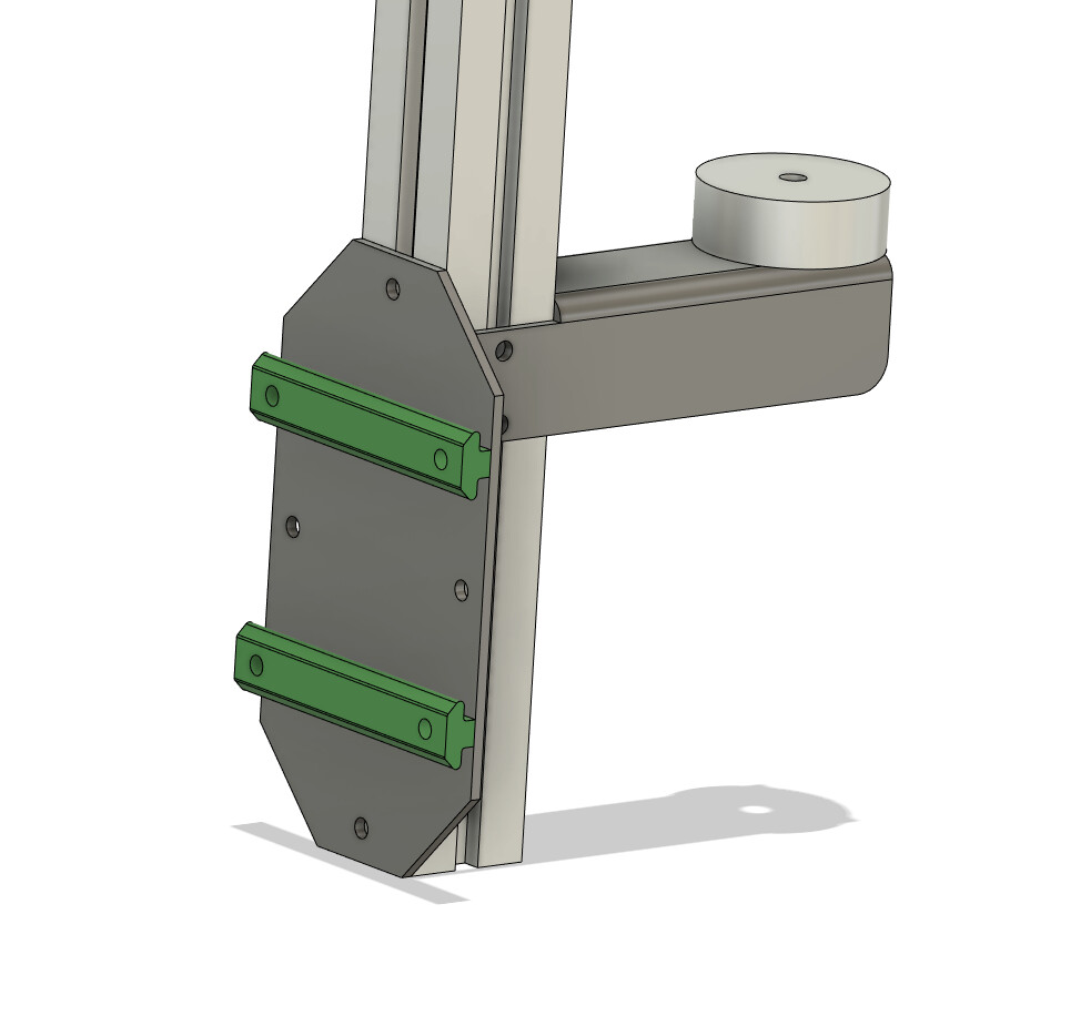
I created a parameterized fixture model in fusion360. I can change the plate thickness and laser cut tolerance, and my model will update all the slots.
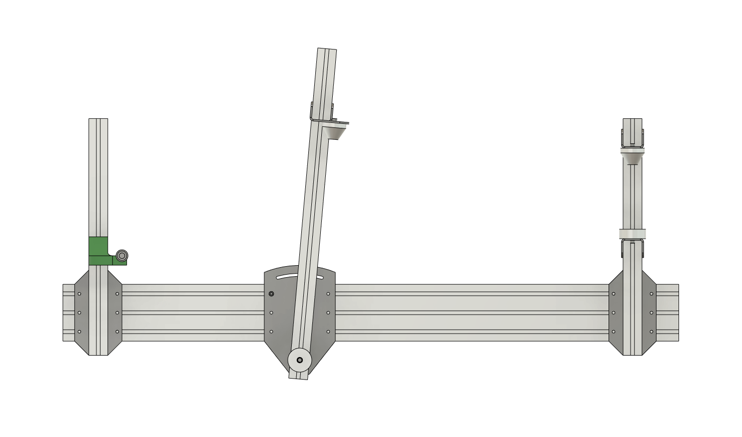
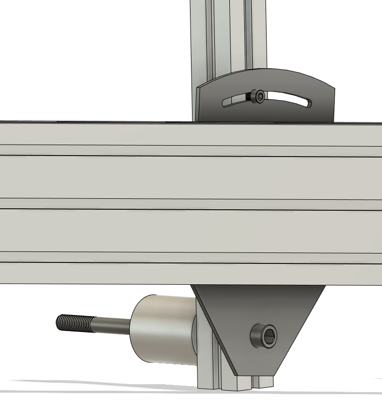
I came up with the idea of adding a .25in dowel pin to index and locate the fixture to the MDF board. You drill a hole in the center of the dropout and the bottom of the headtube so the setup is repeatable. The HT puck and dummy axle are both concentric to this pin.
That’s something I’ve mentioned in the past. For a jig, you don’t need the entire 4x8 sheet. So a few strips cut from the sheet can be made into reinforcing ribs on the bottom of the jig. That of course assumes you get a nice straight cut on the strips with a table saw or such.
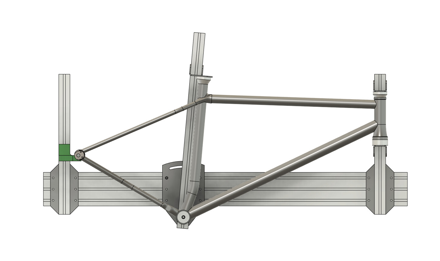
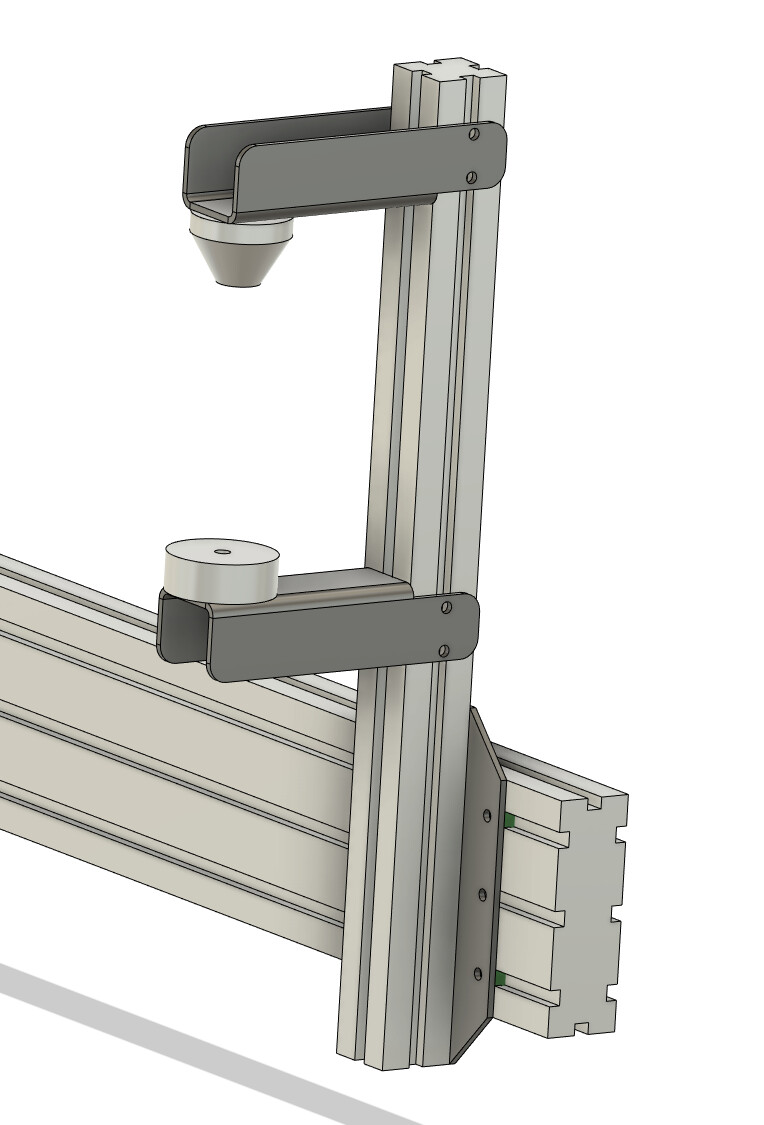
As per @drwelby X-Y suggested, I used a HT coordinate system. As far as I know, it’s the same as the cobra system, except this BB-ST sub-assembly is fixed, and the HT and DR sub move.
Amazing how many different means to similar ends people have developed!
I use the Brew fixture. The feature I really appreciate is the bottom of the main beam is the axle line, so I can quickly check my critical dimensions (which I tend to do obsessively). The actual HT and ST angles, BB drop, rear axle location, and head tube location (fork length) can be directly measured without any calculations. I’m sure once you’re comfortable with a calculation system it’s great, but I really like to see the actual numbers.
This type of layout is easily and often used on extrusion fixtures too.
Thanks for the BREW fixture suggestion. It looks like a pretty reasonably priced fixture and pretty sturdy.
Agreed on having clear datums. I also think it’s pretty nice to be able to set your fork length. Less chance of making a mistake and the error does not propagate. I see one potential issue with my design is that the setup relies heavily on an abstract HT-centered coordinate system. Mistakes in the jig setup or inaccuracy will propagate through the geometry in weird ways.
If I get some time ill try designing a brew-style 8020 jig.
I currently have the top surface of the extrusion at a fixed 160mm distance from the BB center. I am still trying to figure out a smart way of squaring up, calibrating, and indexing the fixture. IMO having reliable scales is the main advantage of the extrusion style fixtures.
I didn’t really consider cost as a major factor when designing my fixture. My budget wasn’t unlimited, but I understood that any fixture was going to mostly be time-intensive. Ease of manufacture of any constituent parts on a lathe and with hand tools was a major consideration, as was the isolation of adjustments (one screw/clamp to fix one degree of freedom) and ease of calibration when assembled.
All of the parts in my design that are of critical length can be made from materials of known thickness (such as gauge or tooling plate), turned to a precise length on a lathe or marked out with a height gauge for accuracy while drilling. All precision holes are the same diameter (Ø12mm H7 reamed holes - could easily be 0.5 inch). There are 3D printed guide elements in the sliding blocks that are positioned using flat reference surfaces and some simple turned delrin pins to guide the head tube and rear axle sub-assemblies. Pointed tips on the cones allow for (relatively) easy measurement of the positions of the seat tube and head tube relative to the main extrusions.
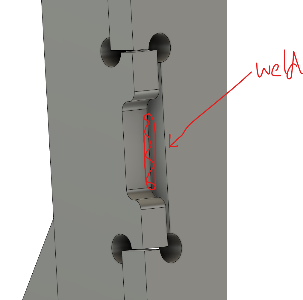
The sheet metal parts are smart and a good use of material, but I think they rely on the closely-spaced fixing holes too much for decent perpendicular alignment to the extrusion profiles. If you can position the fixing holes further apart or mount the sheet metal to the face of the extrusion rather than the side I reckon it’ll be better. I think that out-of-plane (side-to-side) misalignment is worse than vertical or longitudinal misalignment.