Ah, great suggestion! The slot-together bolt-together design might be the most accessible (no welding required) and stiff design. I’ll see if I can do a draft later.
If anyone is interested in how to go about making a Hockey Stick fixture and then using it to build a frame, please let me know and I’ll write something up.
It can quite literally be a 2x4 with a hole drilled in it and a bolt/2 washers, though it’s generally worth investing $20 to make it from metal/nonflammable material.
-Walt
@Waltworks That would be very useful for the community. If you draw some napkin sketches and a write-up, I can create the 3D drawings to make the diagrams for each step. Just post it here, and ill add a new post on the educational resources forum.
IMO, the more well-doccumented solutions, the better.
The cost of this extrusion fixture is slowly creeping beyond $600 after you factor in all the little bits and pieces. Having more accessible options and instructions would be great.
A short update on my progress:
I have the plates, extrusion, and hardware ordered from send cut send, 8020, and mcmaster. Once I test what works and what does not, ill post an updated BOM, part numbers, and pictures.
Subscribing to this thread to stay tuned for more on this!
Rainy Day Update!
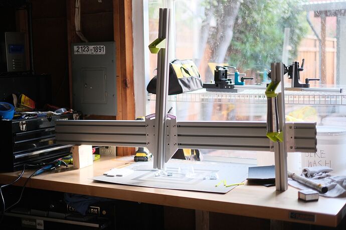
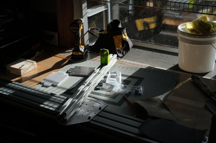
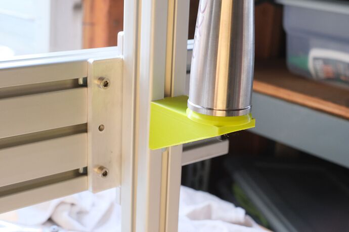
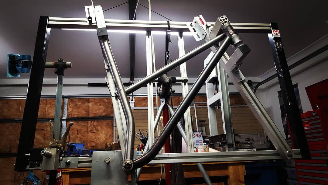
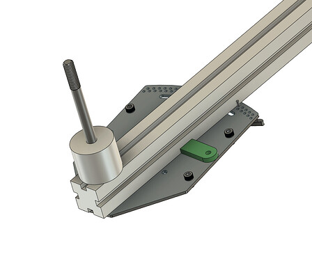
After 2 weeks, I finally got my extrusion from 8020. The neon green 3D-printed risers are just placeholders. They are intentionally short to save print time. Although… they work surprisingly well… ![]() I also somehow managed to order only one of the short extrusions…
I also somehow managed to order only one of the short extrusions…
Hot: 


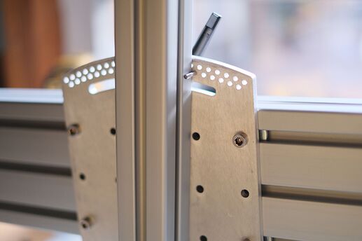
Angle Index System:
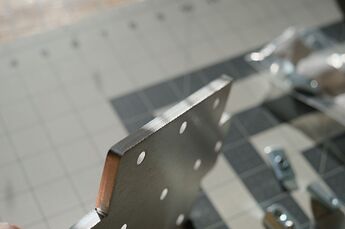
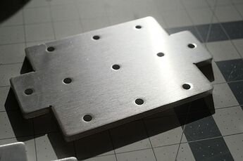
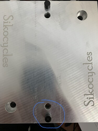
The angle index system works surprisingly well. With the pin locked, it’s +/.1 deg accurate based on my digital angle finder. Right now one hole represents one degree, and I need to figure out how to get half-degree accuracy. I originally had half degrees, but I had to make a last min change because SCS said the holes were too close:
We need all cut features to be at least .088" wide with .075" between any circle and edge in .250" 6061 aluminum.
Laser Cut Aluminum:
I have zero complaints about the laser-cut parts. I choose .25tk 6061 because they offered deburring services w/ aluminum. The aluminum parts were $120, but I think the weight, deburred edges, and cleanliness outweigh the cost savings if you cut it from steel.
Not: 
Weight:
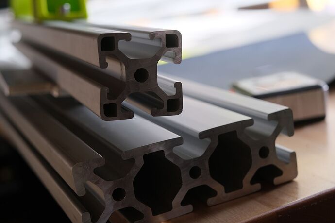
This thing is a TANK. I think the 40x120 base extrusion is overkill. The 40mm extrusion has a “lite” option with extra cutouts to save money and weight (see picture). The 40x120 offered by 8020 is only available in thick.
I also think the 120mm “height” is overkill. It’s nice to have a middle slot though…
A couple of options im going to look at:
M6 bolts are too big:
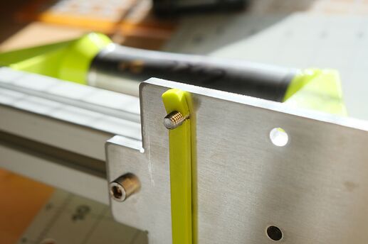
The design needs some sliding keyways to constrain horizontal movement. The slot is only 8mm wide and I was trying to use a M6 bolt. I think the bolt is too wide for the slot. I will have to decide between a mix of M5 or M6 bolts, or just using M5 throughout.
I know this is 3D printed, but even if it were made of brass, I think its too close for comfort!
Todo:
- Drill the 12mm for the M12 BB bolt
- Converge on a laser cut riser design
- Test a smaller main beam (to save weight and cost)
- Talk to paragon about producing cones
- Figure out how to make the sliders slide
- M6 vs M5 bolt decision
In the end, I’m pretty surprised at how easily it came together! I think the next biggest challenge is the risers: what is the best balance between accuracy and manufacturability?
I like the placeholders, it seems like 3d printed head tube holder set would be perfectly fine. For the extrusion nuts, I’ve had good luck with 5/15-18 8020 economy t nuts, they’re reasonably priced. Seems like they have metric options for the 40 series extrusion that you’ve selected.
Pretty sweet you were able to build it up so quickly! The indexed angle adjustment is a clever and simple solution.
I think the best angle finder idea is from Engin’s and PVD’s jigs, that use math and a digital caliper to measure the angle from a known point. I wish my fancy production jig did this. The etched angle marks aren’t accurate. I rely on an old digital angle finder. [Edit: my jig’s scales are accurate. It was my old angle finder lying to me.]
I’d argue that you want all the extrusion and cantilevered parts as beefy and stiff as possible. Extra weight isn’t a bad thing. That way your jig can be your go no-go gauge. I’ve used extrusion based jigs before and I was never sure if my top tube and chainstay lengths were right because the cantilevered parts flexed so much.
That is great. Happy to see it coming together.
Has to be much lighter then mine.
My jig is a tank. 160x80 main beam and 80x80 upright.
1” think aluminum plate.
It’s worth noting that the costs for metric extrusion and hardware from 8020 are about 10-20% higher than fractional depending on what you’re getting. It’s not a huge cost difference, but it’s something worth considering when there’s a budget goal for the project.
I agree with @manzanitacycles, the digital angle finder is the key tool to getting this type of thing set up right, and the weight matters to an extent to the hobbyist builder, but being sturdy is great so long as it’s not too heavy to move on your own.
Your fixture is looking good, looking forward to seeing it in action!
I used the ‘picture frame’ style when I made mine. Spent about Aus$300 by the time I was finished. There is a little bit of set up in it as I haven’t got scribed in markers. I am going to rebuild so it’s quicker to set up and even more accurate. Though it’s prettydarn good as it is. Alignment wise I zeroed it using my surface plate, I know my center line is within 0.1mm over the whole frame contact points. Will do both the mtb and road bikes.
This is how I did it. Not sure if it right. I am not an engineer
I did delein plastic plug guides with the bolts and t slot nuts.
I can take better pictures if needed. Keeps it straight and easy to move.
Frame fixture? Or squat rack? ![]()
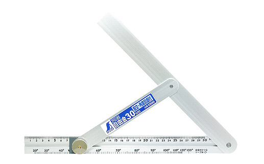
I came across this tool in my research:
I explored using that sort of system with a custom scale. In the end I deemed it was too convoluted to calibrate for a beginner.
I agreed. It’s reasonable to move, but shipping was a pain, and I don’t think the 40x120 is structurally efficient. My eyeball FEA is telling me that this extrusion is heavy but not torsionally stiff. I think the 80x80 might have a higher stiffness-to-weight ratio.
Since I was dumb and forgot to order one of the extrusions, I’ll consider grabbing an 80x80 to do some back-to-back comparisons with my 30lb kettlebell. I know our mtb front triangles are roughly 100Nm when welded up, so it would be interesting to see how the stiffnesses of the fixture compare to the Mtb frames.
Very nice! That fixture is gigantic, but I wouldn’t be surprised if it were similar weight to my current design. It also looks like it has a lot of room to work around!
I’m honestly surprised by how much cheaper people had built their current fixtures. Maybe it’s the inflation?
This is actually a great size. A friend’s fixture is base extrusion of 3x6 8020, it’s much more sturdy than 1.5x4.5. Some builders want to make cargo bikes and tandems which can require a bigger fixture.
It’s likely inflation, design choices and shopping.
Probably weighs about 15kg (33lbs) at a guess.
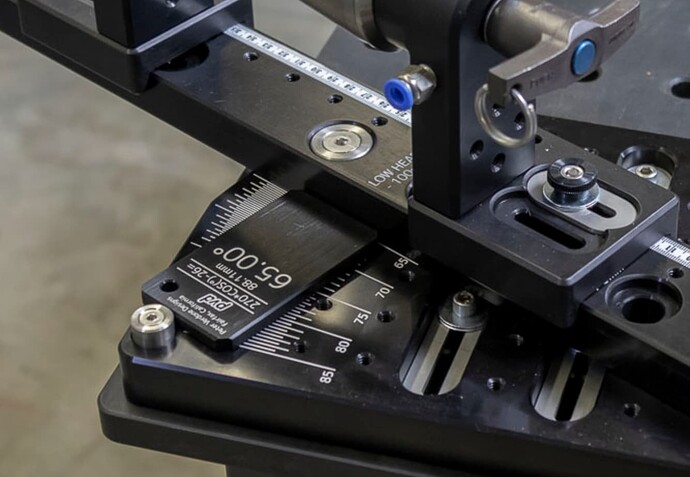
I was thinking more like this:
Some triangle math gets you the distance between a fixed nub and the adjustable arm. In this case PVD uses little angle tokens. This gets you a consistent angle every time. It’s simple and foolproof and likely easy to build into a hobby level jig since you only need to drill one hole for the nub. Then you can print out the tokens as needed.
LOL I could, I will need to weigh it sometime to see. It is pretty heavy
I like @manzanitacycles proposal, between the markings and the plate for common angles, you are covered pretty well.
If you want to keep the holes, and I do trust more the precision of a 1M dollar laser machine vs me eyeballing stuff, why not moving the half degree holes higher? Lower they probably won’t fit but higher? You would need to enlarge the plate but…
For the cones, why not using cheap headsets? I bet most framebuilders will simply need to have two or max three headsets to cover all their needs and you can find tapered or straight fork tubes at a framebuilder supply, heck, most framebuilders will have older spare headsets laying around ![]()
Tokens is a good idea. Especially if you build a fixed angle geometry (HT and ST angles are coupled w/ this design). I am trying to leave the design as modular as possible to leave people with some room to add functionality and experiment:
On the next iteration, I will try to figure out if it’s feasible to do half-deg holes. You end up with double the holes with half the spacing, so it’s really pushing the design constraints of the laser. I agree that making the plate bigger is better overall, but I’m curious what that cost tradeoff is. Even the holes add to the cost because the laser needs to travel more!
As others have pointed out the angle finder is both cheap and accurate, so this might just be an academic pursuit haha. Although I think having multiple methods of verification is always good.
That’s a great suggestion. I will look into it. My gut reaction is that the headsets will turn, but maybe there are ways around it, maybe it does not matter, or maybe it’s even good for alignment!
Cant you just mill a pin in half for the half degree? Instead it being round just flatten a side?
