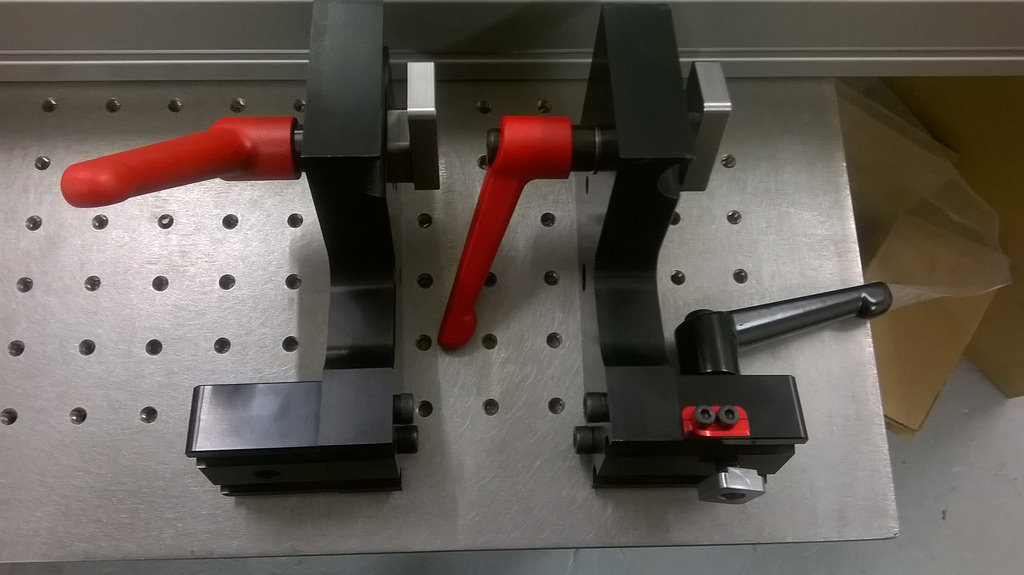
Yes something like that.
Making a half pin may be too bendy BUT, on the same idea, making a pin that is 1.5 times wider like so:
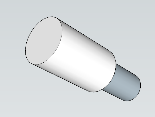
With the same idea, one could have a couple of different sizes pin, let’s say +0.5, +1, +1.5 and the plate could have less holes, holes every 2 degrees and then pins to cover +0.0, +0.5, +1, +1.5
A builder could machine it’s own pins for finer adjustment
One step further, you could have sleeves made for the pin, so one pin with a +0.5, +1, +1.5 etc sleeve, sleeves could be made out of plastic as well
The SKYNET system also uses the cosine bar / tokens system, but I just use my dial calipers to set the distance. A few thou off is such a small difference in angle it’s not necessarily worth worrying about.
Although, cheap gage blocks do exist. Nice to have in the shop for other things too, of course.
I’m selling a couple of water-jet cut angle plates for the skynet system if anyone is interested. Could potentially finish machine these as well for the right price. I also have modelled the entire skynet fixture to get a better understanding of how it works if anyone is interested in the CAD files. Particularly useful if you plan to have anything on it CNC’d or Water-jet cut. I realised I was more interested in building a bike than building a fixture and that building the fixture was just me procrastinating on building the bike itself. Speaking of which what is the simplest frame fixture one could make for a one off frame? The Yamaguchi cones on an alignment table posted in another thread looked good.
Update:
Had some time this weekend to chug along on the design a bit
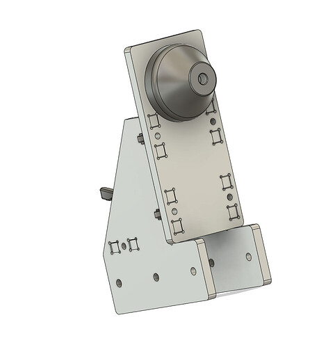
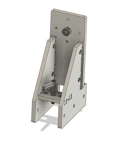
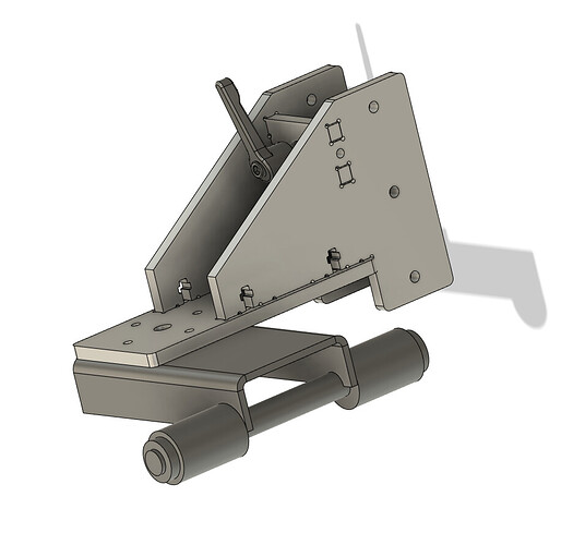
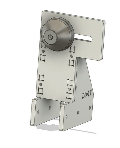
Risers:
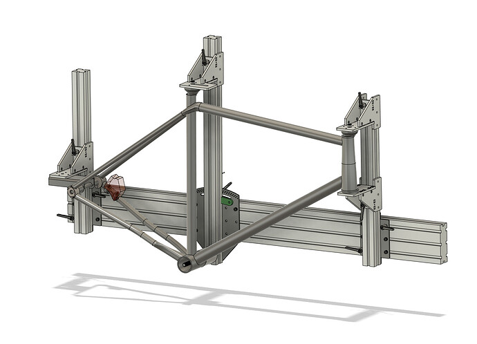
I decided to try a pettis joint construction method. There was some intelligent GD&T to get the proper fit and squareness, but I honestly don’t know how square and how well the structure will hold up. Won’t know till I try:
I still feel like this whole fixture is starting to become overbuilt and creeping in scope ![]()
The plates are modular to allow customizations and reduce cost:
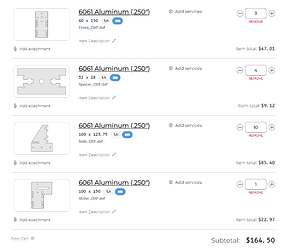
Cost:
The price of the risers is roughly $45/each which definitely pushes the budget. Scaling down the thickness from .25 to .187in reduces the cost by ~25%
The 3D-printed rises were surprisingly robust and really cheap. It might make sense to fork the design to a budget and mid teir design later. I will test out the slotted aluminum to see if it is worth it!
Cones:
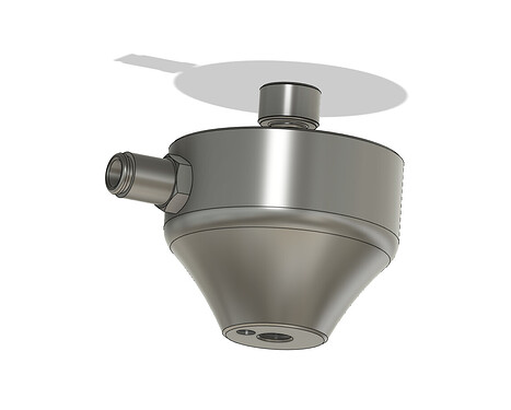
I’m lucky to have Todd Farr as a resource to consult on the cones. He gave me the concave geometry he uses for his BFF fixture. The concave geo bites into the tubes more securely than a simple cone.
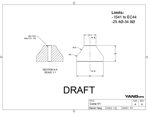
It’s designed to accommodate:
- Seat tubes as small as 25.4
- IS42-IS41 standards
- EC44 headtues
- MAYBE T47 shells
One thing that I am still stuck on, is whether or not to include accommodation for a back purge port. It would be nice to have but would drive up the cost per unit. I have a feeling someone who needs back purge will have the skills and knowledge to install one themselves. What do other’s think?
I also got the team at Paragon onboard with the open source fixture idea. They are willing to produce the cones (obviously still contingent on the design). I am hoping that this cone becomes a small piece of a larger open-source fixture/jig architecture for framebuilding.
Scope:
Having played around with the designs and talked with builders and suppliers, I narrowed down the scope of this project:
Requirements:
- Can be built without a mill or lathe
- Well documented
- Fully indexed
- Low cost
- $500
- Accurate
- +/1mm planarity
- Easy to use
- frame can rotate out
- International
- hardware can be sourced on all continents
I think the cost is the hardest requirement to hit right now. Inflation, shipping costs, and the little hardware pieces add up. Once I can validate the design is solid, I will see if there are ways to bring down the cost without compromising the other requirements. I hope to make the design modular, so people can build it with what they have access to, or pick and choose the costs:
- threaded rod instead of dummy axles
- thinner plates everywhere
- steel plates instead of aluminum
- smaller main extrusion
- split the main extrusion in half to save on shipping
Adding the small push-lock pneumatic fittings would be fairly trivial for most folks. Maybe just add some to the model to get the idea across?
I’m about to do that to my skynet jig. I never worried about it at first, but all the cones/pucks have enough room in them to add in the fittings later on.
Also, that’s such a forehead-slappingly-obvious idea. I can’t believe why some company like Paragon with the tooling and machines already don’t make the occasional run of off-the-shelf cones and such for framebuilders. Seems like that’s always a hurdle when designing a cheap frame jig.
Since I have the extrusions from my jig I have now I could make one of these pretty cheap.
I would skip the back purge to make it more reasonable or have an option for the buyer. . I think most will build with steel so it is “not” needed.
To be fair there are already sources for appropriate cones in the motorcycle building world, so it’s not like they don’t exist.
-Walt
To keep the cost down (and the weight), can some parts be made out of plastic? The downside is that most of them are cut via a CNC router and that is more expensive than cutting via CO2 laser so maybe there is not a lot to be saved.
Have you tried oshcut.com? Their setup costs are higher than SCS but they have a different material lineup, I have used them before CSC and they always produced fantastic parts.
I know there are existing options, but why not have a cheaper, better-designed cone, and keep the money in our industry? I want the moto guys to be buying from us!
Good idea. If you add a fitting on the side, the tradeoff is that you need extra material at the base of the cone to give room for different fittings. This adds more 30% more material cost, which is going to be significant if they are to be made in stainless.
I can propose both designs to them to see the cost difference.
Years ago I had some cones of my design made by Alex Meade. One difference in my design vs the one above this post is that I had a raised portion standing off the top of the cone that the fixing bolt would thread into. That way I could separate the jobs of locating the cone on the fixture and attaching the cone to the fixture. If I understand your drawings correctly, the fixing screw is also performing the locating of the cone. Maybe that’s intentional?
Here’s a snippet from the drawing I submitted to Alex that shows the feature:
For reference, I stuck these cones into 8020 angle brackets and the diameter of the standoff was such that it formed a transition fit with the holes in the brackets.
Daniel,
Do you have CAD files for the cones? Happy to make them, but we’d like to make the most generic, one-size-fits-most cones. Are there any standard cones to copy so they’ll interchange? Anyone used the Chop Source cones as a prototype? Maybe a stepped cone to hold both English and T47? Or a universal cone that does all BB shells and headtubes? If it’s not possible to make a universal cone, let’s at least make sure that the interface is identical across the line.
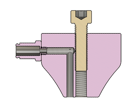
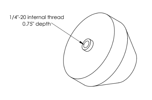
Correct! With laser cutting, a tight clearance hole (8.2mm), and a regular bolt, I was able to get decent enough precision. I would guess <.1mm of wiggle. The goal of this cone/project is not to make the most precise, but the most accessible, universal, and hackable.
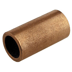
I think if someone wants more accuracy and has access to a lathe, I think there is an option to counter-bore a 10mm hole and press in a bronze bushing:
That being said, thats just my opinion on the design. The M8 tapped hole was just an educated guess, im open to what others think.
My reasoning was: With M8 tapped, you can always drill it out clearance if you need to. M8 also feels like a good size to me ![]()
On my jig I used stepped shouldered inserts rather than cones. Only use a cone for the seat tube top. Makes for very accurate holding and easier jig set up. Just as a data point for your own set ups.
we used to sell this entire kit for £750 uk you just bought your own extrusion
the plans were even put out there because people though they could make them cheaper so we let them
fixtures are really a race to the bottom with every person having their own desire demands and interpretations
if i was going to be honest withyou the sheet metal design is the good option you can go as thin as 3mm which will save a ton of weight think of those optical tables which sandwhich a core between two plates i worked many years ago weith some ultra precision stuff and we could hit 1 micron repeatably iirc it was 2010 and when you have to sit and do proper calculations for silly high accuracy fictures you often find the fixture sags under its own weight , designing low mass for highest stiffness is quite an interesting challenge , which is why for cheap things machining out of solid plate is sometimes the fast route , a lot of these tooling plate fixtures are utter less than optimal, but they serve a purpose and piling layer after layer of machined parts is often a rapid way to get the job done
Hey Everyone! @Daniel_Y Thank you so much for putting this forum together, this thread especially.
I haven’t made formal introductions on this forum yet, but I’ll save that for another thread. In short, I’m a product design student working on my capstone/ thesis project right now. I’m focusing on both designing and building cool bikes, but also taking something of an outsider’s look at the process. My first and only frame was built on a sheet of MDF with 3d printed standoffs. It worked, but it’s not a process I want to go through again.
Anyway, I’m designing a jig right now that shares some of the same objectives as this project-
- Low cost- think “motivated student” budget
- Simple to fabricate- avoid overly complex machining, makerspace equipment or less
- Wide range of adaptability- offset/bent seatposts, full suspension, XXS to XXL bikes
- CAD integrated- I want to avoid the adjust and check loop. Geometry numbers are punched into Fusion360, and the model automatically generates inside the fixture
- ** Open Source-** CAD and documentation will be Creative Commons as it develops
I don’t want to derail things, or just propose my version of your fixture, but I’d love to share my progress here and get some feedback.
Welcome! I’m obviously biased, but I think your project and objectives are a great idea and sorely needed.
Feel free to jump into this thread. It is a brainstorming thread for all open-source fixtures and ideas, I just happen to be leading most of the discussion because I am working on it ![]()
Once we converge on a final design, I will create a new thread with all the design details and instructions.
Feel free to jump into this one. Or for a school project, it might make sense to create a separate thread on the education forum to have clearer documentation.
I bumped your membership level so you should be able to post pictures and create new threads.
