Egress Bikes - Leftover Tubes Hardtail Build

I haven’t been actively building for a while now and I got rid of a lot of my tools (frame fixture, torch etc), but I’ve had the itch to build myself another hardtail recently. So here’s a build log that I hope some of you may enjoy.

I’ve had a pretty good idea if what I wanted this hardtail to be ever since I finished and delivered a customer frame back in 2020 - it ended up being one of those bikes that I wished I’d kept for myself (though it was the wrong size, so that was lucky for the customer I guess).
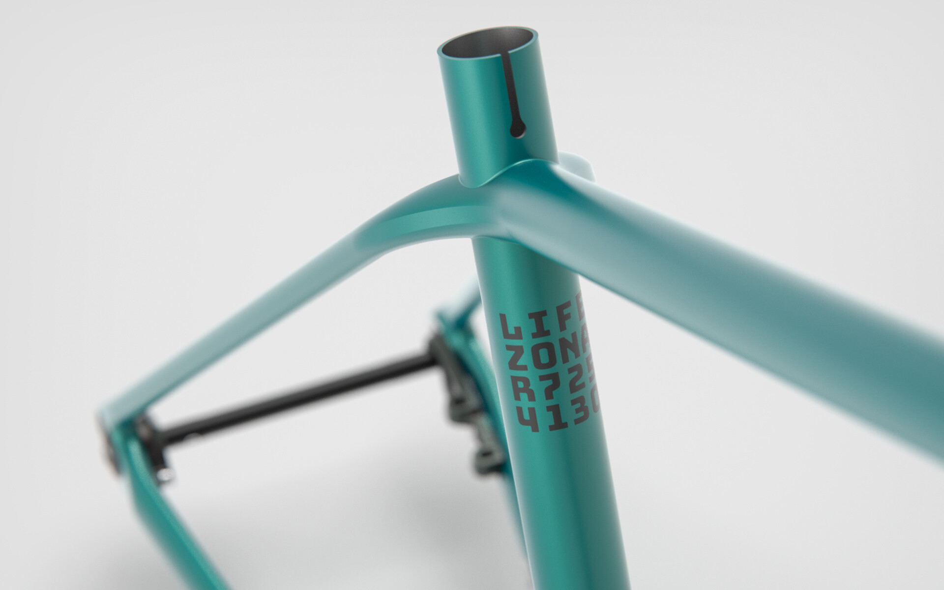
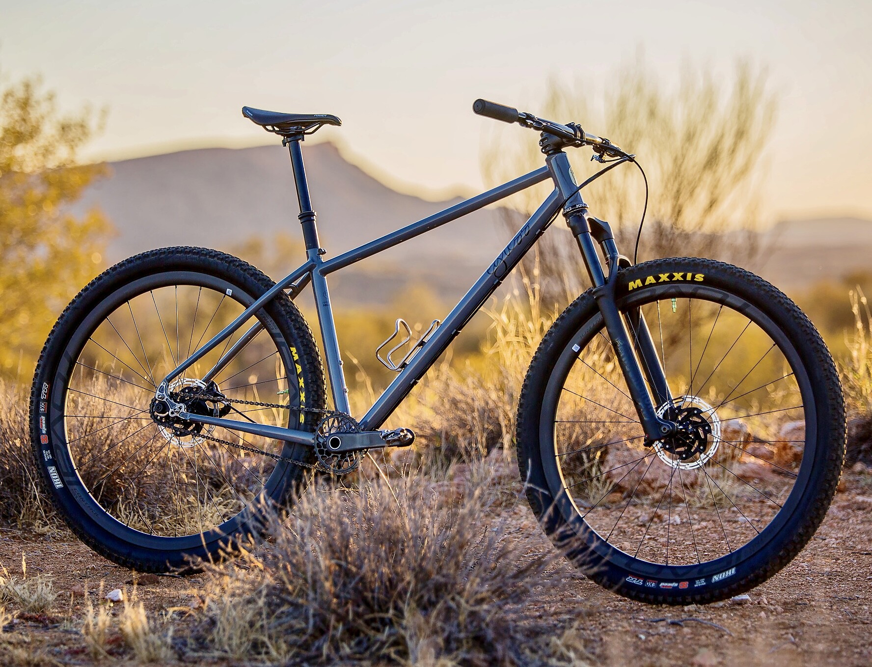
It was a clean 29er singlespeed built around a 120mm fork. Columbus Zona tubing. PMW 44mm headtube, BB and Rocker dropouts finished in a timeless Nardo Grey with black logos.

Something about it just ticked all the boxes for me and I’ve wanted one for myself ever since.

Here is a photo of it in its natural environment:

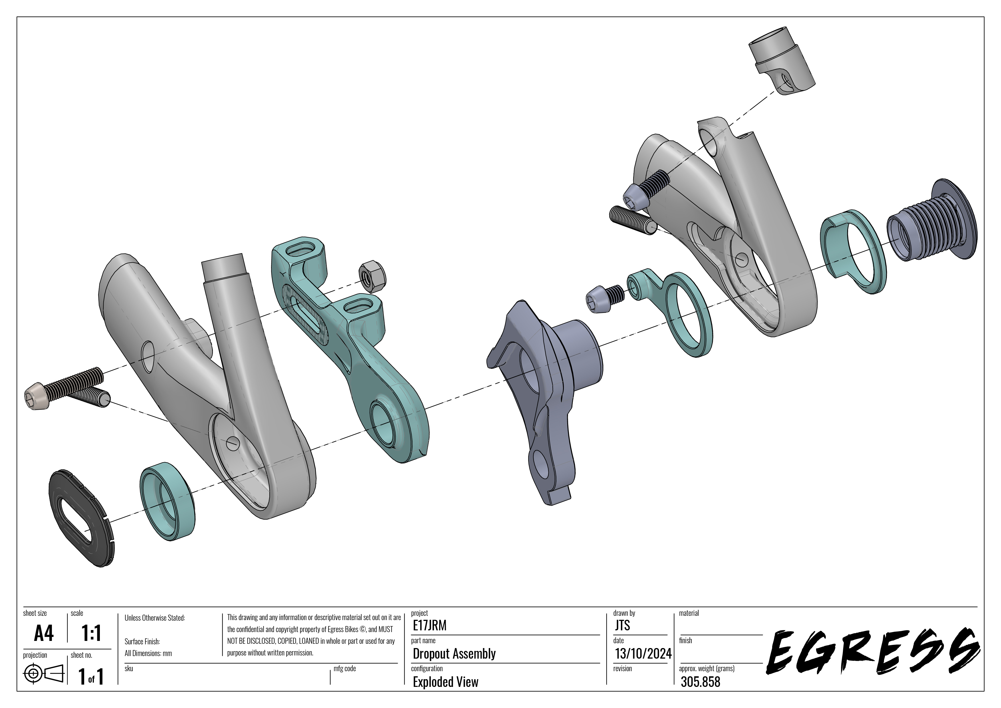
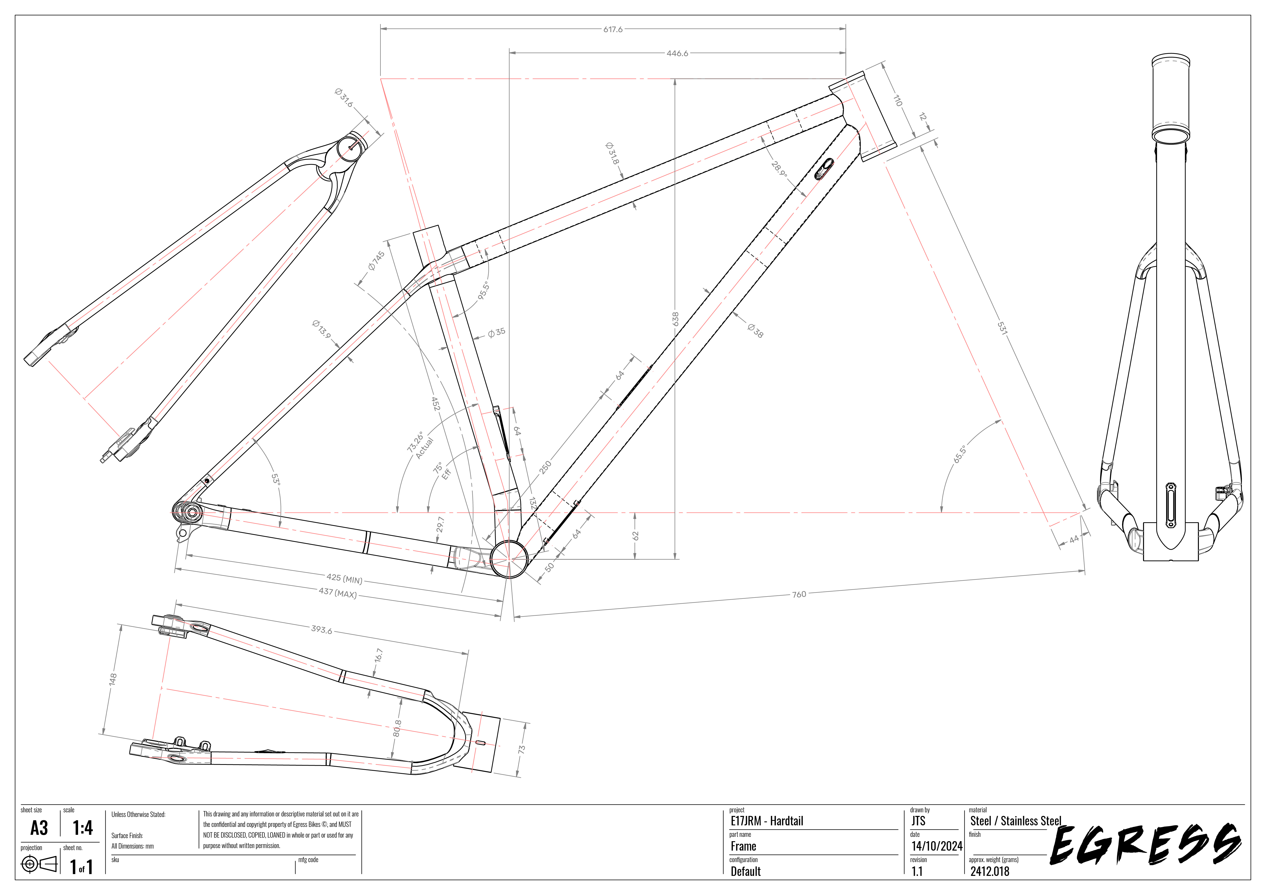
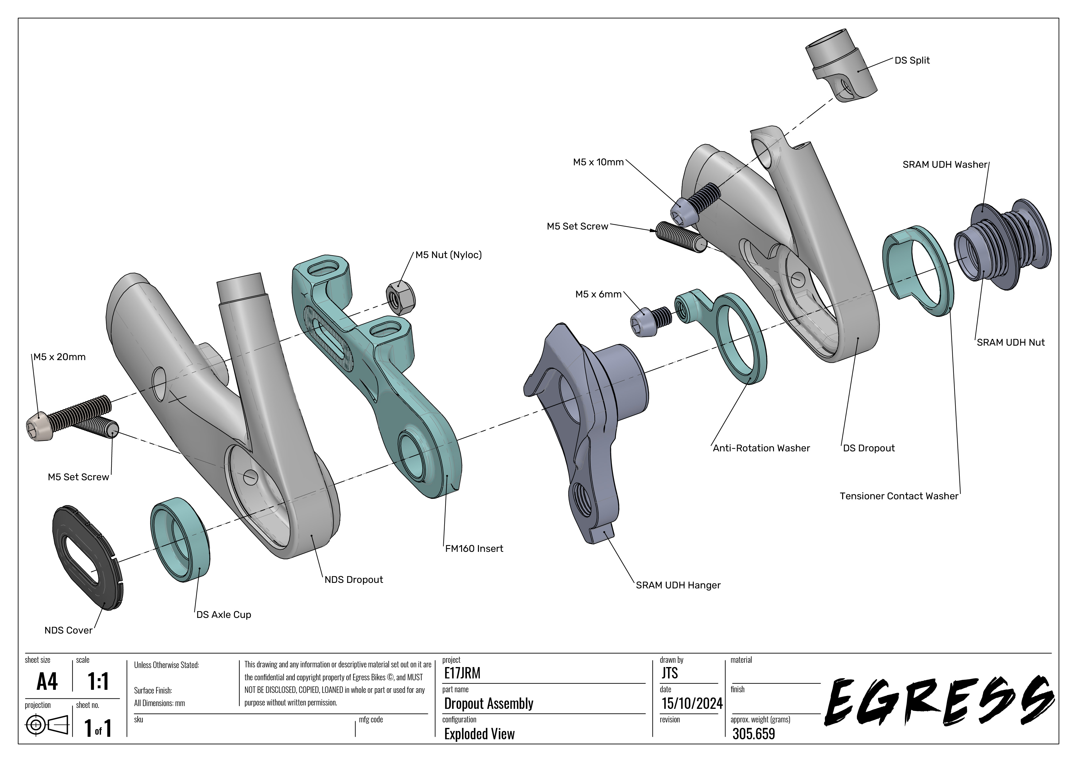
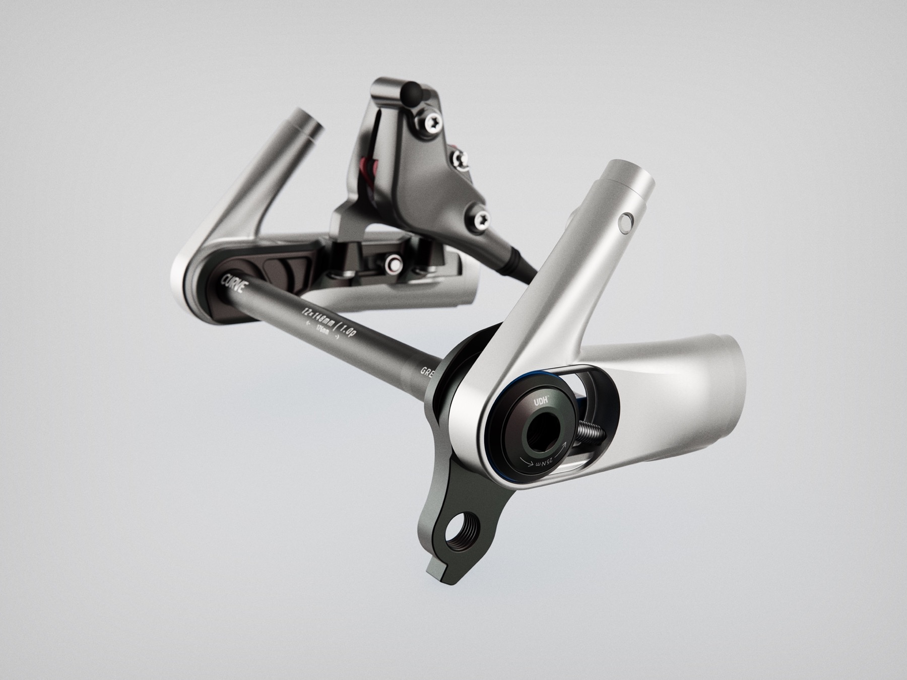
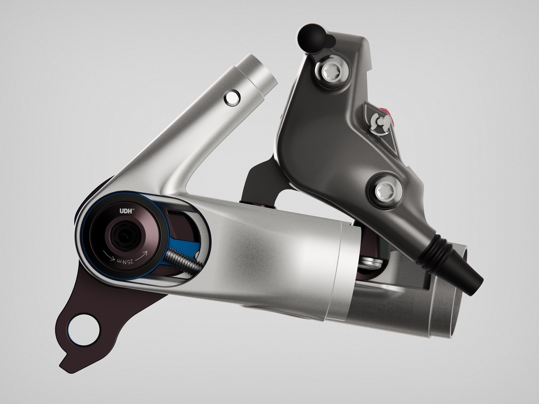
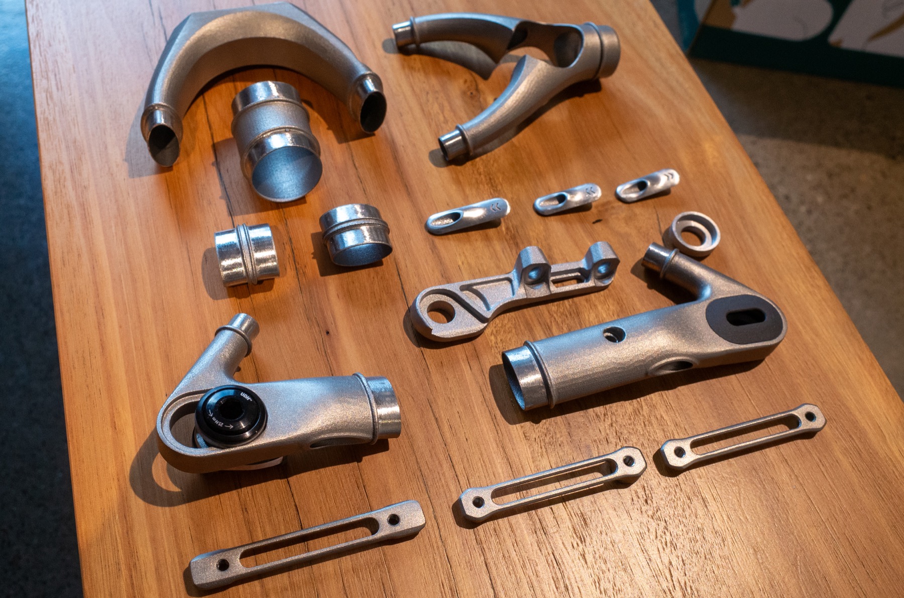
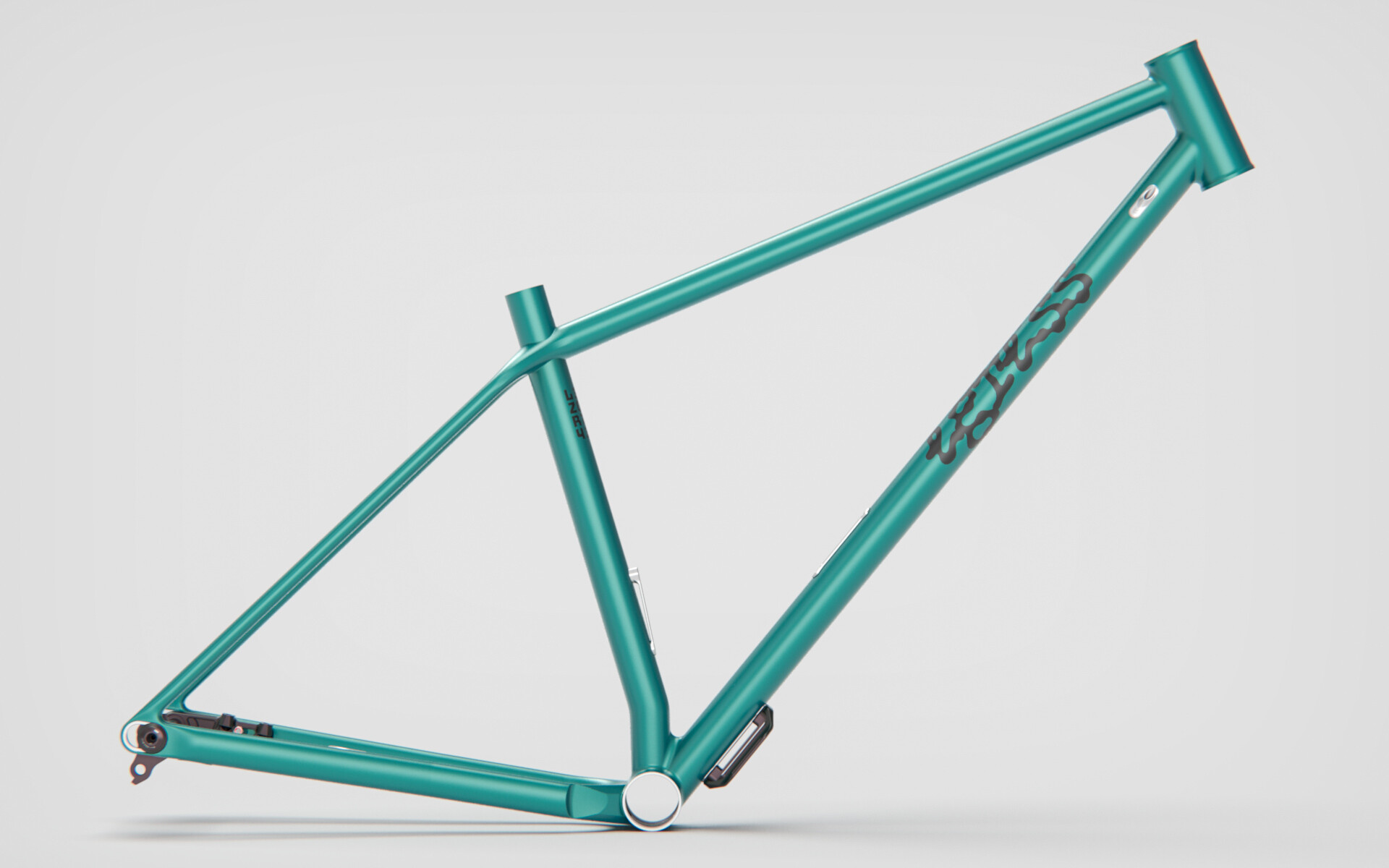
Fast forward to earlier this year and we got some stainess steel 3D print samples of set of UDH dropouts I desiged for my day job. The idea was sparked that I could build a frame for myself to “test” them, so I got to work and dialled in the geo in BikeCAD.


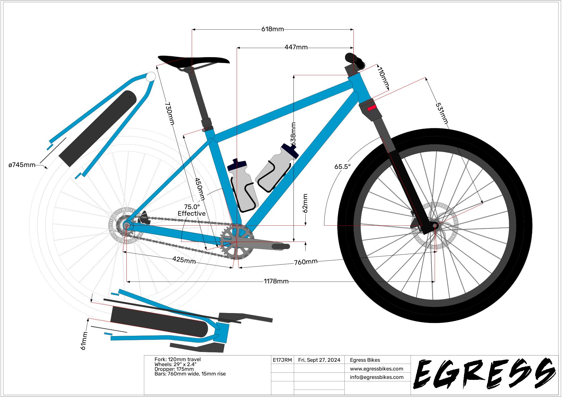
[Some geo tweaks may still be needed.]

Digging through stuff in my garage, I found a bunch of leftover Columbus tubes, a 73mm PMW T47 BB and a selection of 44mm headtubes and hatched the plan to use what I have instead of buying new tubes.

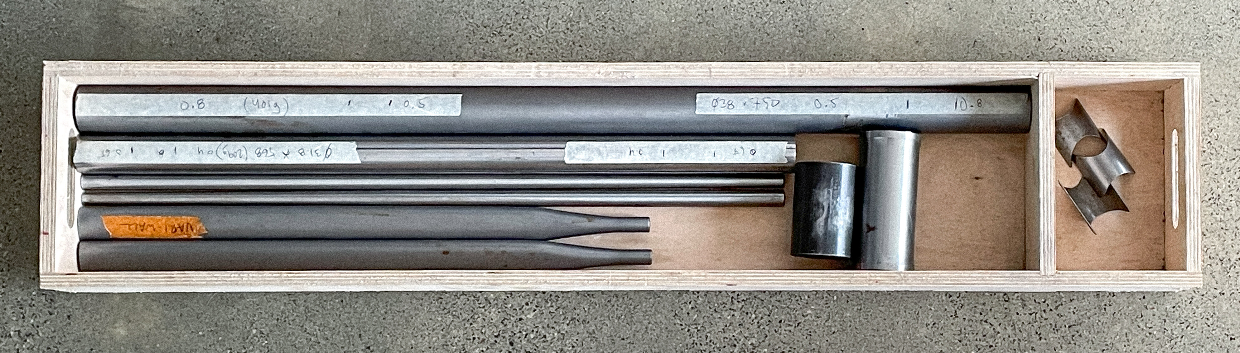
The seatstays I found were just a set of straight Columbus SL, the chainstay option I initially picked from my leftovers box was a set of Columbus Life 16 x 30 short taper with a mellow road bend, and the Ø31.7 Columbus Spirit tube I found would not be long enough to use as a toptube. So this is where the simple “leftover tubes build” ended up getting a bit more complicated.

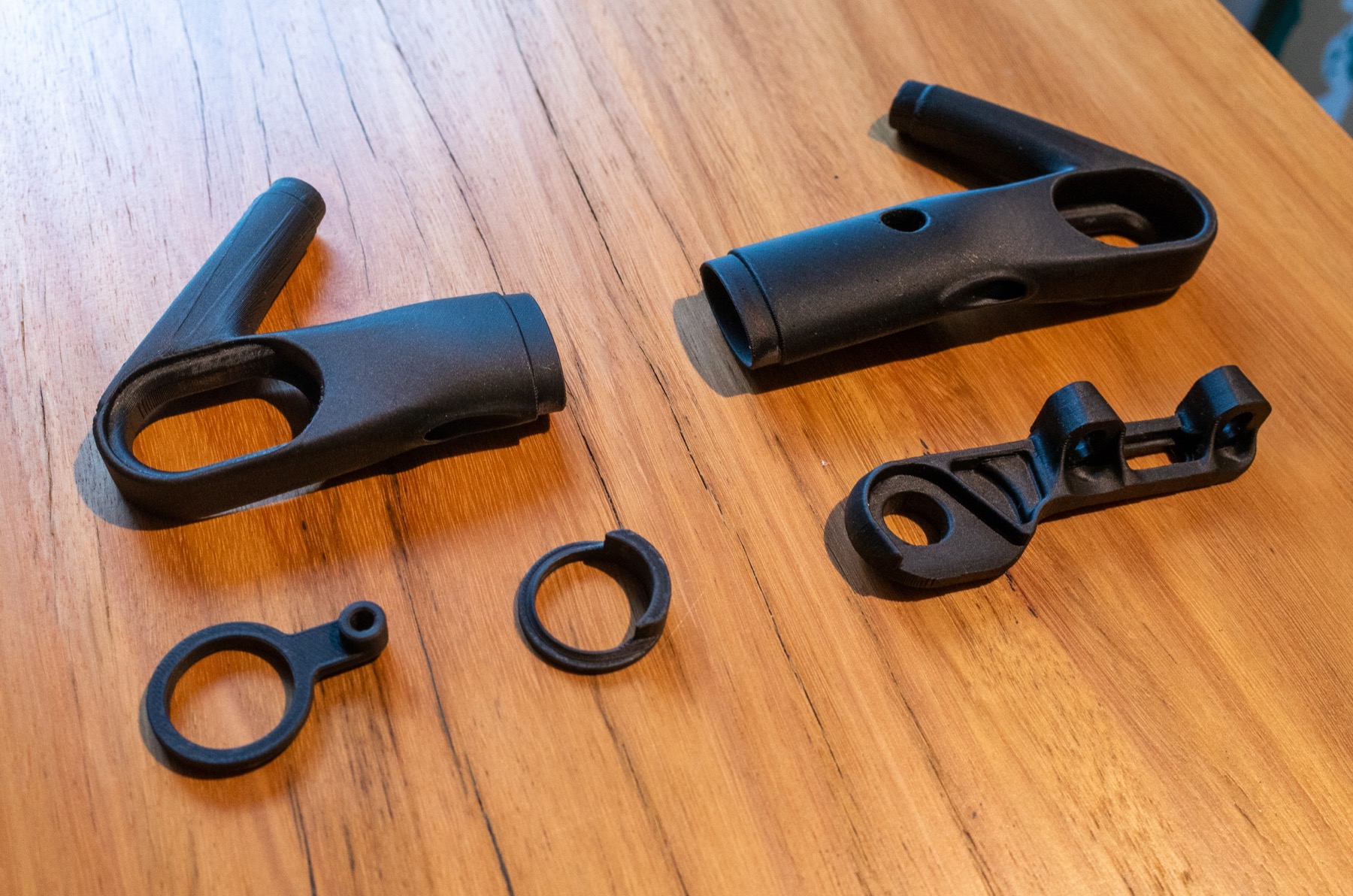
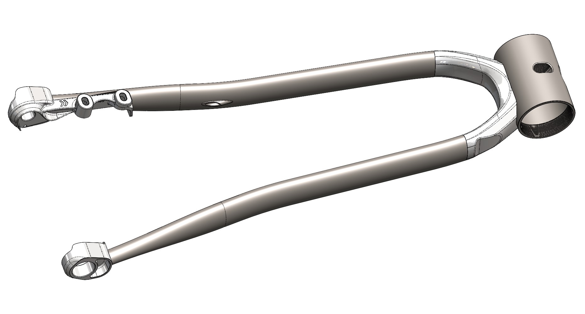
I don’t have a tube bender and no way to shape oval tubes, so the natural decision here was to design a set of yokes to be 3D printed out of stainless steel. This is where I had to continue the project in SolidWorks instead.

The SS yoke would conveniently also take care of the too short TT as I could simply extend the 3D print a bit to give myself just enough length to allow it to be mitered to the TT and have a straight-cut join to the yoke section.


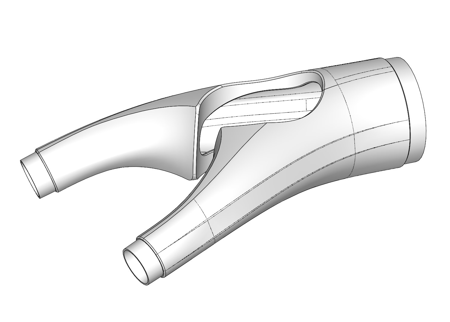
[I know, I know - this yoke is very similar to @Daniel_Y’s design. Not that many options when trying to flow three tubes together. But I reckon I’ve added some of my own subtle ‘flair’ to it.]

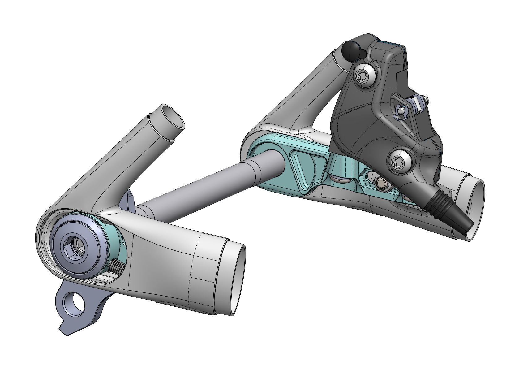
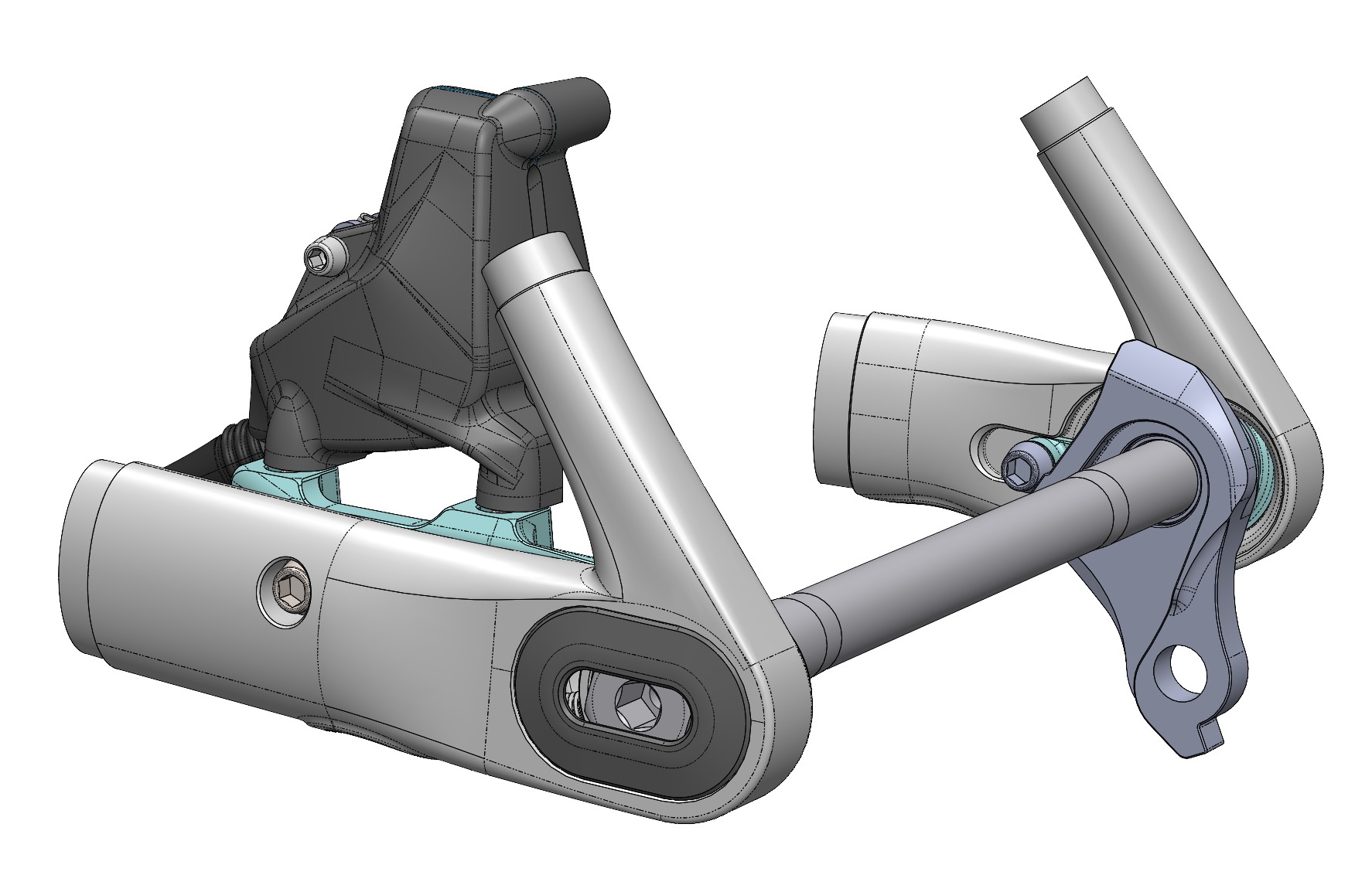
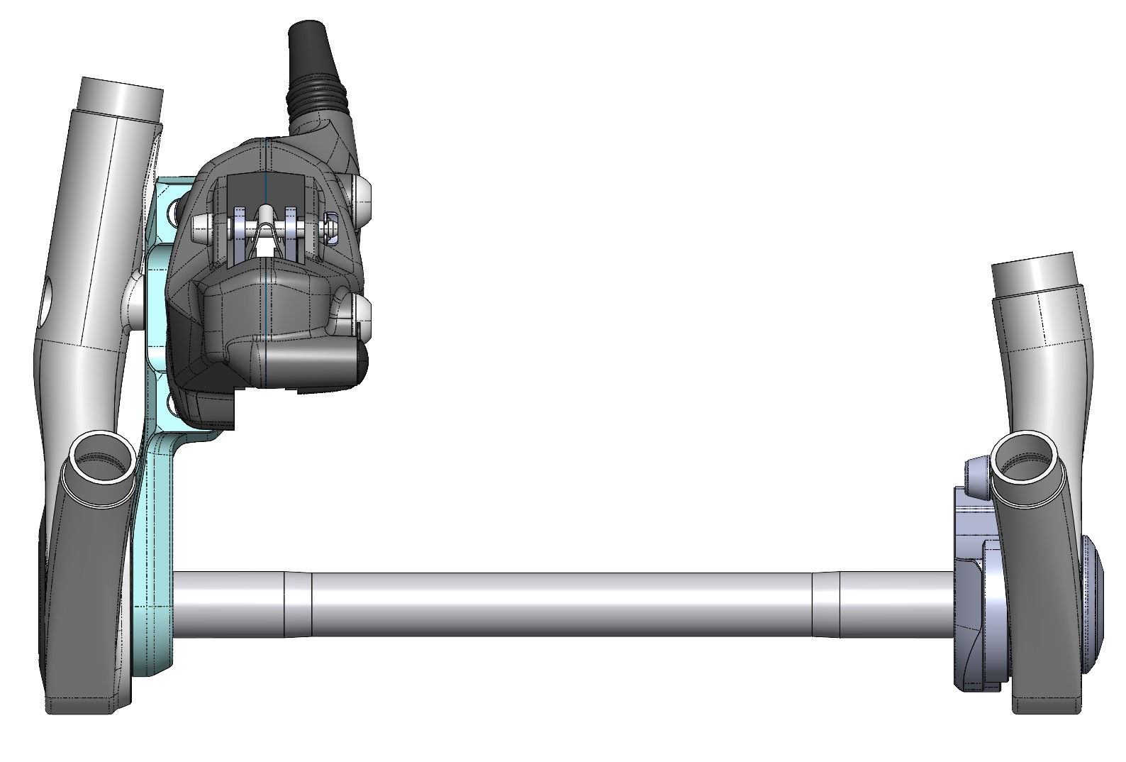
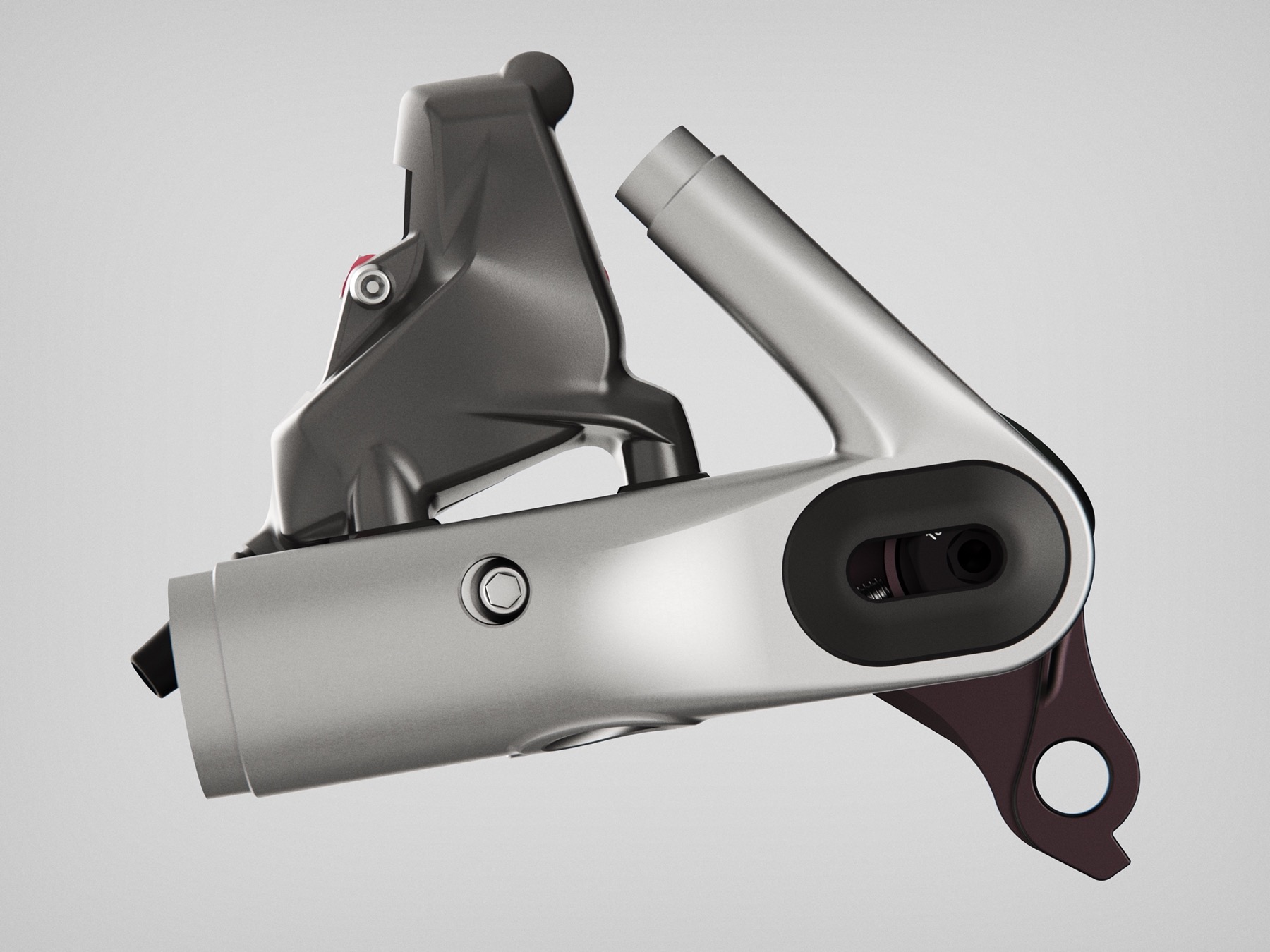
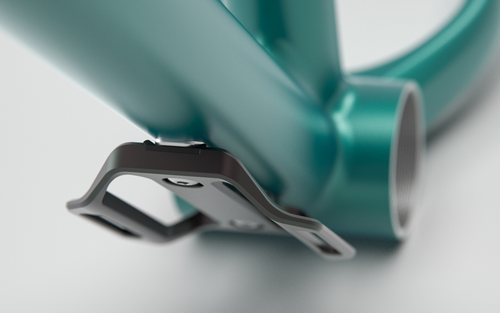
Next up was to design a chainstay yoke that would marry the road bend chainstays to the T47 BB shell while giving me the clearance I wanted. Giving this frame room for up to 29" x 2.6" tyres, but I’ll probably end up riding 2.4" tyres for the most part. I even managed to get the stays to work quite well with those prototype dropouts that kind of kicked off this whole project.


[Yup. Flat mount.]

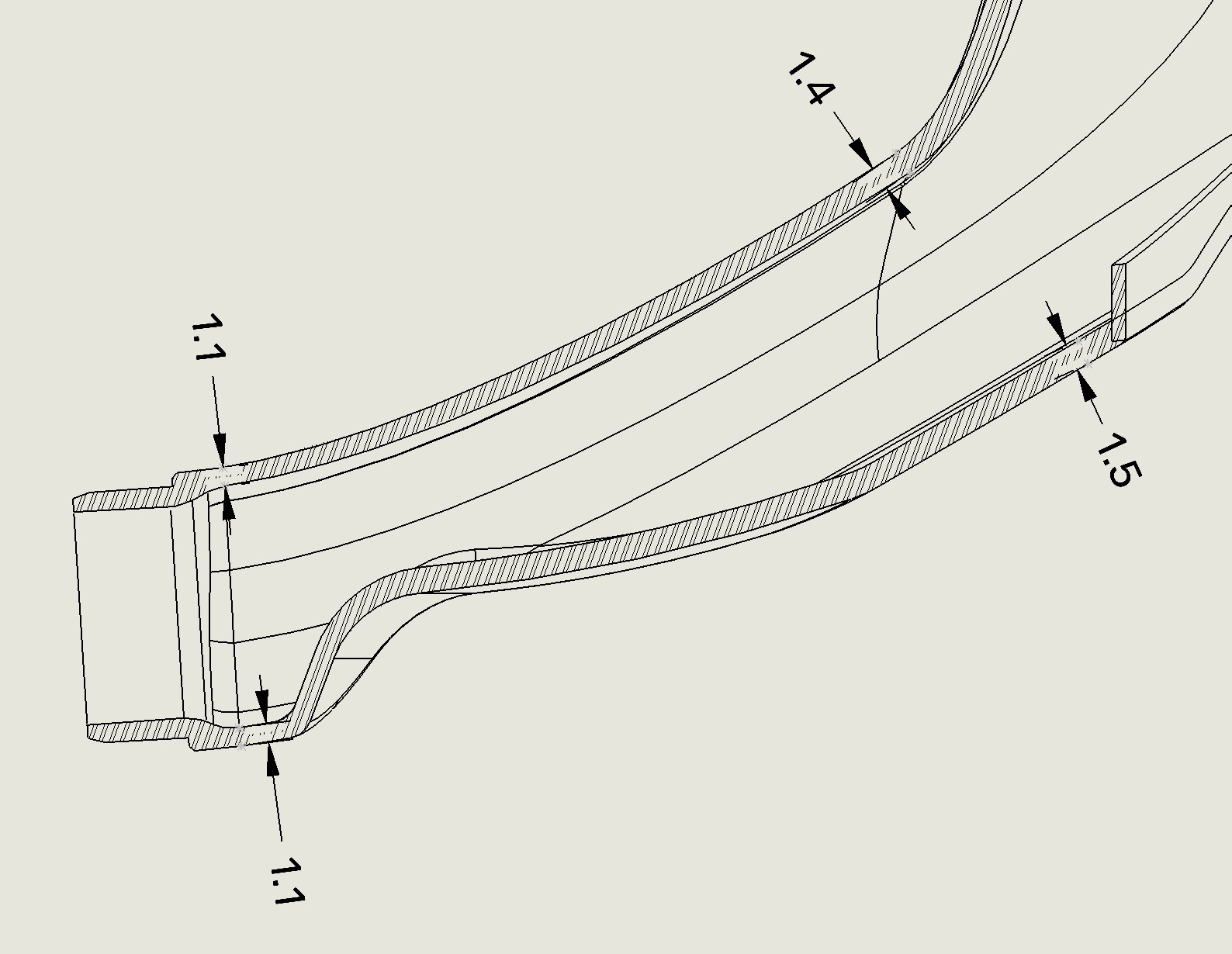
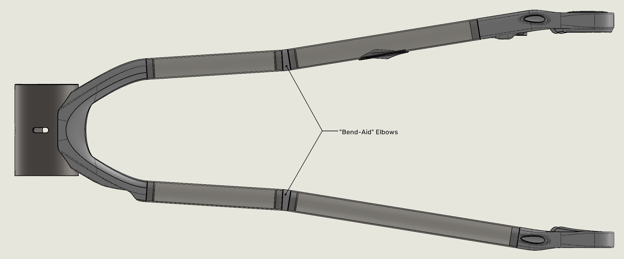
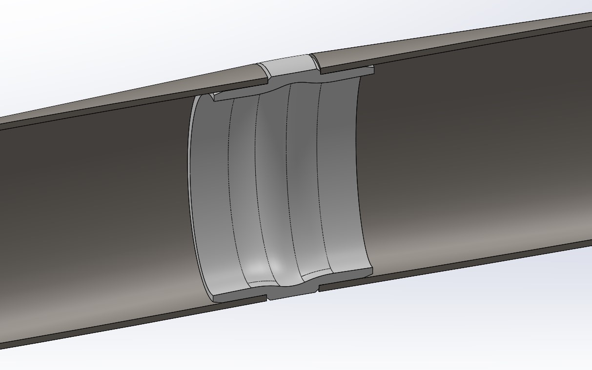
Next up was the seat tube bend. As I mentioned before, I don’t have a bender and didn’t feel like bothering other local builders to help me bend one, so while I was at it designing stuff to be 3D printed I figured I could make a printed elbow that can be used with just plain 4130. Easy.


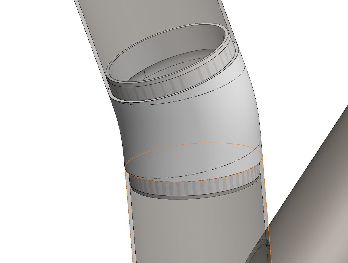
[It’s a Bend-Aid fix.]

End part 1.

18 Likes

At this point I had invested quite a bit of time and effort into the design of all the bits to be 3D printed. I was happy with the progress and felt it was just about time to hit go and upload the files to get them printed… but as I was trying to save my work, SolidWorks flaked out on me and corrupted the file which made it impossible to save. With a fair amount of unsaved work that I was forced to nuke, I decided to start from scratch instead of reverting to a previuos save in case there was something inherently wrong with the original file.

Since I’d been using the project as a way to get better at modeling for additive manufacturing, learning and utilising more surface modeling features, I took this as an opportunity to refine and clean up my models, make them more robust and almost fully parametric and also work on getting nice and smooth curvature transitions between surfaces where necessary.

I re-modeled both yokes from scratch and managed to incorporate some fancy details such as a wall thickness in the CS yoke that gets gradually thicker towards the BB shell, so it’s essentially a butted yoke.


[Maybe completely useless, but a neat detail nonetheless.]

At around this time I also started second-guessing my decision to use those printed UDH dropout samples for the build. I wasn’t sold on the short taper section of the chainstay, and how it looked joining up to the dropouts. I also couldn’t shake the idea that wanted to be able to run this bike singlespeed and the prospect of running a tensioner or eccentric BB did not appeal to me. The easy way out would of course be to just pick my usual go-to sliding dropout or a set of rockers from PMW.

Well, I’m not always one to make life easy. And after all, I’d sunk all this time into the project already, so why not go ahead and design new dropouts and make the frame really unique? Because I didn’t want to forego the UDH and Transmission compatibility I was quite excited about trying out on this frame, the only choice was to finally start work on something I’d been thinking about ever since UDH became a thing - a neat and compact sliding UDH dropout where the hanger itself is like the sliding insert.

The change of plan regarding the dropouts also meant that I could no longer make the pre-bent Life chainstays work, so I dug up a set of nearly identical, but straight, chainstays from Vari-Wall and modeled up another “Bend-Aid” - a 3D printed elbow for the chainstays to add the bend I need for crank arm and heel clearance. I’ll just cut the stays to the appropriate lengths and silver-braze the elbows in place.


[Another Bend-Aid solution]

As an added bonus of this approach I’ll be able to get rid of the tapered section of the chainstays and make the oval shape flow straight into the new dropouts. 16 x 30mm chunky oval goodness all the way from the yoke to the dropout.

As usual when I get started modeling something more complex, I’ll have an idea in my head but I struggle to make it all come together on the screen. This is where some hand-sketching skills would come in handy - but I just plain suck at that so I have my own trial and error method of modeling to get to the shape I want before adding the more intricate details of the actual sliding system.
It took some headscratching to figure out how I could make this idea of mine work out, but I think I’ve ended up with a pretty neat solution.


12mm of length adjustment and I can use a modified (chopped hanger tang) UDH hanger for a clean singlespeed setup. Fully UDH and T-type compliant in the rearmost position. When slid forward, the back end of the dropout will interfere with the “No-Go Zone” in the UDH clearance model.

The non driveside insert is set up for flat mount and a 160mm rotor with no need for an adapter. I should be able to design another insert for post mount as well. To counter torque from braking, the forward part of the insert rests on a shelf integrated into the dropout. An M5 bolt & nut will help keep the insert in place and should also help with retention.

2 x M5 grub screws accessed from the underside of each dropout takes care of tensioning duties. I figured this would be an essential feature so as to not have to rely solely on the thru-axle to have enough retention force to keep the wheel from moving.

If you’re wondering what the black thing covering the axle on the non drive side is, it’s a cap that snaps in place to disguise the big opening in the dropout that’s needed to house the axle head and sliding mechanism. The slot is big enough to still get an allen key in there to loosen the axle for adjustments. The cap only needs to come off when taking axle out to remove the wheel.

End part 2.

11 Likes

your CAD work here looks super tidy, and I like the complex but not complicated design.

and generally thanks for posting; it looks like you work in some ways that sound similar to me, and in some ways I would like to more, so its nice to follow along. I think it’s always nice to have more of this stuff to see.

It’s not immediately clear to me if there is much beyond the axle tension stopping the wheel being pushed backwards, say while braking hard through ruts; is this where the 2x m5 grub screws from underneath come in?

2 Likes

Cheers Patrick!

I’ll have more to post soon. :slight_smile:

I didn’t really consider the wheel pulling back as a possible issue, but it’s a good point. I’ve only ever had forward slippage happen from pedaling torque on other bikes and that’s what the bolts from the underside will help with.

The axle tension would be what takes care of most of the retention for backwards slipping. But the M5 bolt from the side will add some retention too.

Maybe I’ll make the surface area where the insert contacts the dropout larger to increase friction. Could also easily make the area serrated (thanks 3D printing) to help lock it in place even more.

3 Likes

A shorter update this time.
Have done some more tweaking to the dropouts. Added serrations to the non drive side sliding element and the dropout itself where they contact each other. The idea is that it’ll help with the brake insert retention once the M5 bolt is tightened.

While I was at it, I figured I could also add a belt drive split. This is a first iteration. I’ve put the M5 bolt at a slight angle, and not perpendicular to the seatstay with the idea that as the bolt is tightened, it will pull the assembly together and not just ‘hold it in place’ for lack of a better way to explain it.

Toying with ideas to make the interface keyed as well to increase the stability.

Getting close to hitting go on the 3D print bits now.
Heading to Bespoked in Dresden tomorrow, and I’ll likely do a few fine-tune tweaks once I’m back next week and then it’ll be time to just commit and get the physical build started!

5 Likes

This dropout is pure genius! I’ve never thought about positioning the tensioners from the bottom at an angle and it’s a game changer. I also love how you only added material to the bb side to prevent it from rotating. It keeps the rear of the dropout nice and tight and is easily one of the best looking sliding dropouts I’ve seen.

2 Likes

Thanks!
It does consist of a few parts and ideally I’d like it a bit simpler, but I think I’ve pared it down as much as possible to still work with the concept I have in mind.

I saw your first (unedited) comment and figured I’d respond to that last bit, but I have a feeling you have already figured it out. The hanger, bolt and washer are standard SRAM parts. The washers you noted are necessary to make up the thickness of the dropout - both are still needed when using a Transmission derailleur.

Here’s the same exploded sketch, but with a description of each part. Most of it should be self-explanatory, but I’ll add some notes below.

Left to right:

  • NDS Cover - I didn’t like the big opening, so I decided I’d try to cover it with a lid
  • DS Axle Cup - I don’t want the tensioner set screw to push directly onto the axle, so this cup gets to be poked instead
  • Anti-Rotation Washer & M5 x 6mm - This bit moves with the hanger and provides the stop for the hanger ‘fin’. The M5 x 6 bolt is there because the full stop “nub” is not required for Transmission derailleurs. I know there’s debate about whether or not the fin on the hanger is necessary, but I’ve decided to keep it. It will act as a stop when undoing the hanger. Especially useful if I cut the hanger tang off for singlespeed use.
  • Tensioner Contact Washer - This is one part I could probably eliminate by moving the tensioner contact “pad” to the anti-rotation washer, but I was unsure how well the standard SRAM hanger washer would hold up when not supported all the way around, so I added this for support.

Oh, and because I’m a geek, I also made some renderings and an animation in Keyshot.


14 Likes

@JMY over here making me feel completely amateur with my CAD modeling skills.
Well done!! I’m very excited to see this built up.

2 Likes

Beautiful work mate. There’s just one small detail that’s hard to see. Is the M5 nut on the NDS captured by the insert or do you need to get a wrench in there to reposition? Looks like a difficult spot to access between the brake mounts.

3 Likes

Thanks gents!

Your work is always top notch, so this praise is very appreciated!

Indeed it is captured. I was very conscious of not making it hard to access any of the fastening & adjustment features.

Scroll up earlier in the thread and you’ll see a screenshot that shows the captured nut better.

1 Like

Damn that’s next level. Very cool design. You should sell them.

1 Like

Beautiful!

2 Likes

Can‘t wait for the build, sounds like a cool concept… and you have some really good cad skills!

1 Like

How I wish, brothers, to change the lower dropouts to upper ones.


Elegant solution for singlespeed and UDH in those dropouts.

1 Like

I’ve been quietly chipping away in the background on this. Not much worth sharing until now.

A few weeks ago a friend of mine sorted out some plastic test prints to validate the design of the dropouts and yokes.
All came together nicely but I did spot a few things that needed some tweaking. Small details in how the washers interface with the dropout recess etc. The biggest change was the larger radius where the seat stay joins the base of the dropout. The print looked scarily thin there so I opted for some extra beef.

Another thing the validation print made me realise was that I’d modeled the flat mount insert to the 140/160 standard instead of 160/180. This was because I originally figured I’d use a +20mm HOPE RX4+ caliper, but those plans have changed, so I re-modeled the insert and made the necessary tweaks to the dropout itself. Luckily my models were modeled parametrically and were robust enough that only small corrections were necessary after I punched in the updated flat mount specs.

I also pulled the trigger and ordered the stainless prints. Opted for 316, glass bead blasted finish from Protosoon.
The package arrived yesterday and everything looks great. They kept the dimensional tolerances spot on. Only some minor sanding needed to make the tubes slide onto their sockets nicely. The hanger fit well with the anti-rotation washers and all the threads had been cut very nicely.

To my surprise, the weight estimates from SolidWorks were within one gram even for the largest pieces.

Getting started on the actual build today.

I’ve also played around with some more renderings to figure out a possible logo placement and colour scheme. I won’t go overboard and will keep it a single colour plus logo. Colour not locked in.


One thing I’m quite pleased with is the cargo bracket on the downtube. Made the 3D printed piece perfectly match the shape of a Tailfin Mini Cage. It’ll probably be permanently attached to the frame so the matching interface will keep it nice and stable.

12 Likes

Those parts look awesome! I’ve got an order coming from protosoon, now I’m real excited.

Are you brazing these, TIG welding, or a mixture of both?

What are the short segment (coupler) tubes for?

1 Like

Holy Shoot. That is so awesome. Great job.

1 Like

Thanks! More updates coming soon.

I’m impressed. The only bits I wasn’t super happy with were the small cable ports. But I may have had too high of an expectation.

I’ll be brazing. No TIG (I don’t know how). All the miter joints will be fillet brazed with either bronze or 30% silver depending on the material, the socket joints will be slip brazed with 56% silver.

They’re my “bend-aids” to put a bend in the chainstays. Had these straight oval short-taper stays in my leftover box and needed to figure out a way to use them.

5 Likes

Wow! Small innovations everywhere.

Are those inserts 3D printed in aluminum? The quality looks really good.

1 Like