I reached out to Autodesk and it turns out it’s a known issue that they are working on.
Thanks for contacting Autodesk support. My name is Tom and I’m on the Fusion 360 support team. I understand you’re having a problem with Drawing dimensions dissociating after even a very minor update to the model.
I’ve checked out the forum post and saw that Clint, the Product Manager for Drawings, has already commented that this is a known issue for Windows 11 that we’re actively working on. The internal ticket number is: FDWG-17237.
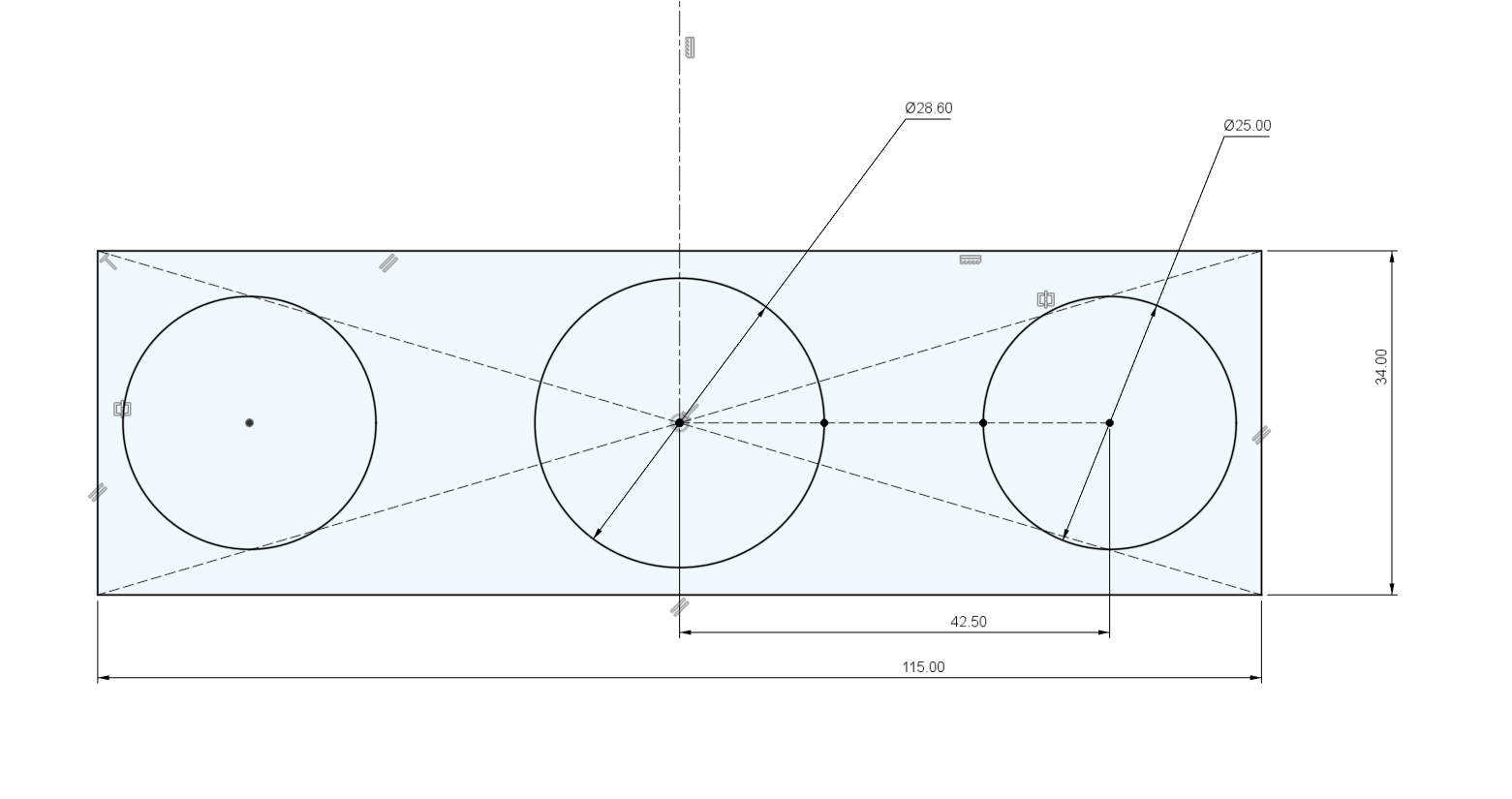
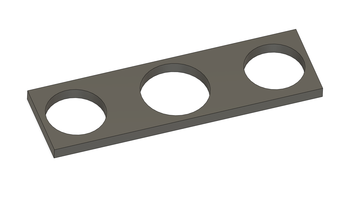
Not sure how to do this. I could use Fusion to create ellipses for holes, but you would still need to file the holes down. See this plate yoke example:
I’ve wanted the ability to make sub-assemblies on the farr miter fixture, now we are getting closer. Inspired by @Daniel_Y design for a dummy BB adapter to the farr miter fixture.
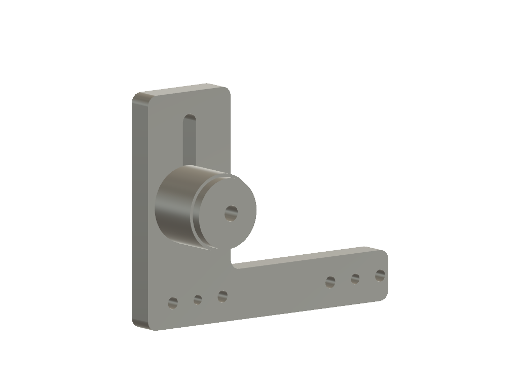
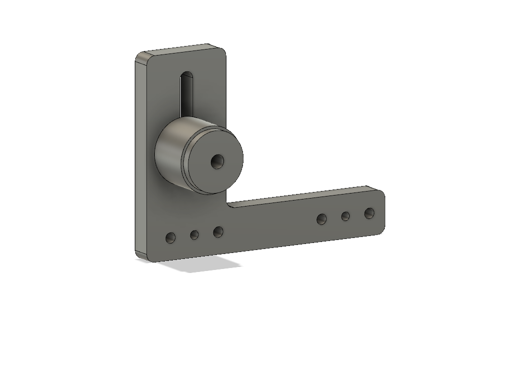
What is pictured is the mount and the puck to hold the actual BB, I would also be having some “dummy” BB made for use with yokes. One set of locating holes would be for the yokes and the other would be for chain stays that are mitered in the fixture.
The puck has an eccentric hole to help dial in the location of the BB in relation to the actual cut that is made. Perfect is cool, but adjustability is crucial as I am imperfect. Currently the hole is 2mm off center, not sure how little or how much eccentricity would be needed. The tower is 1/2" thick.
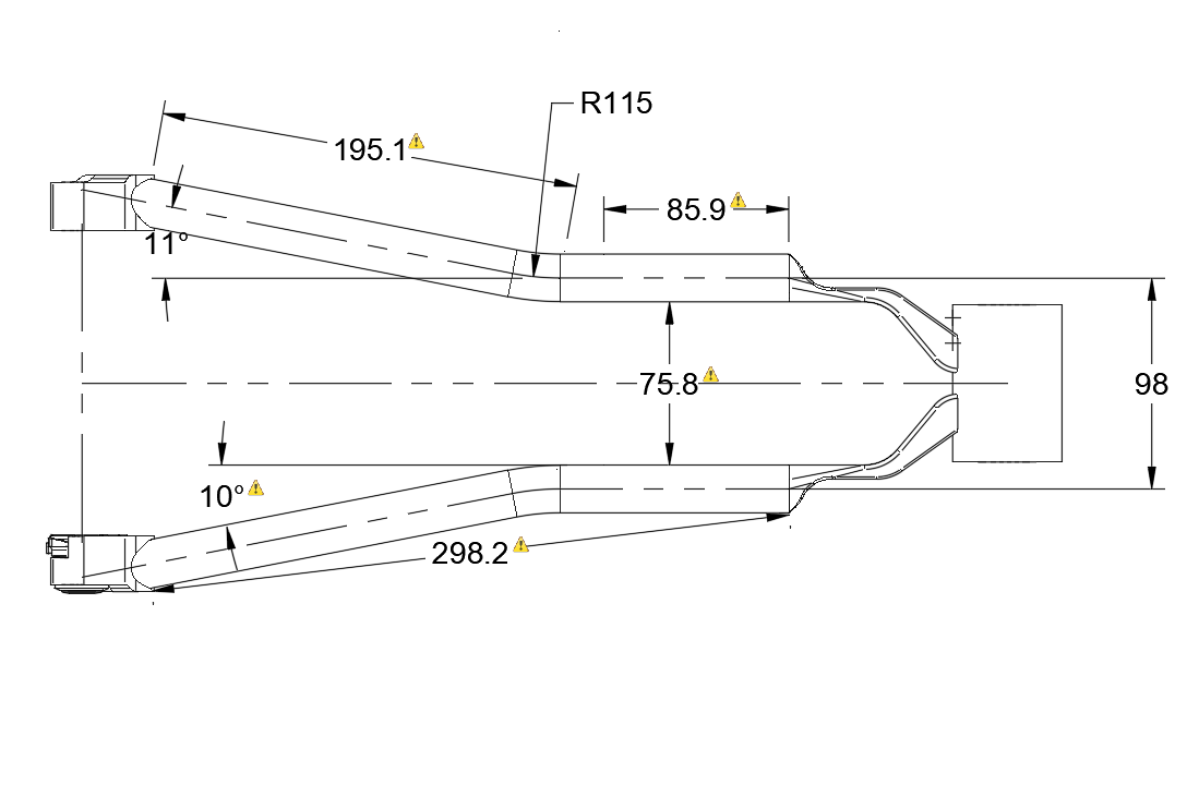
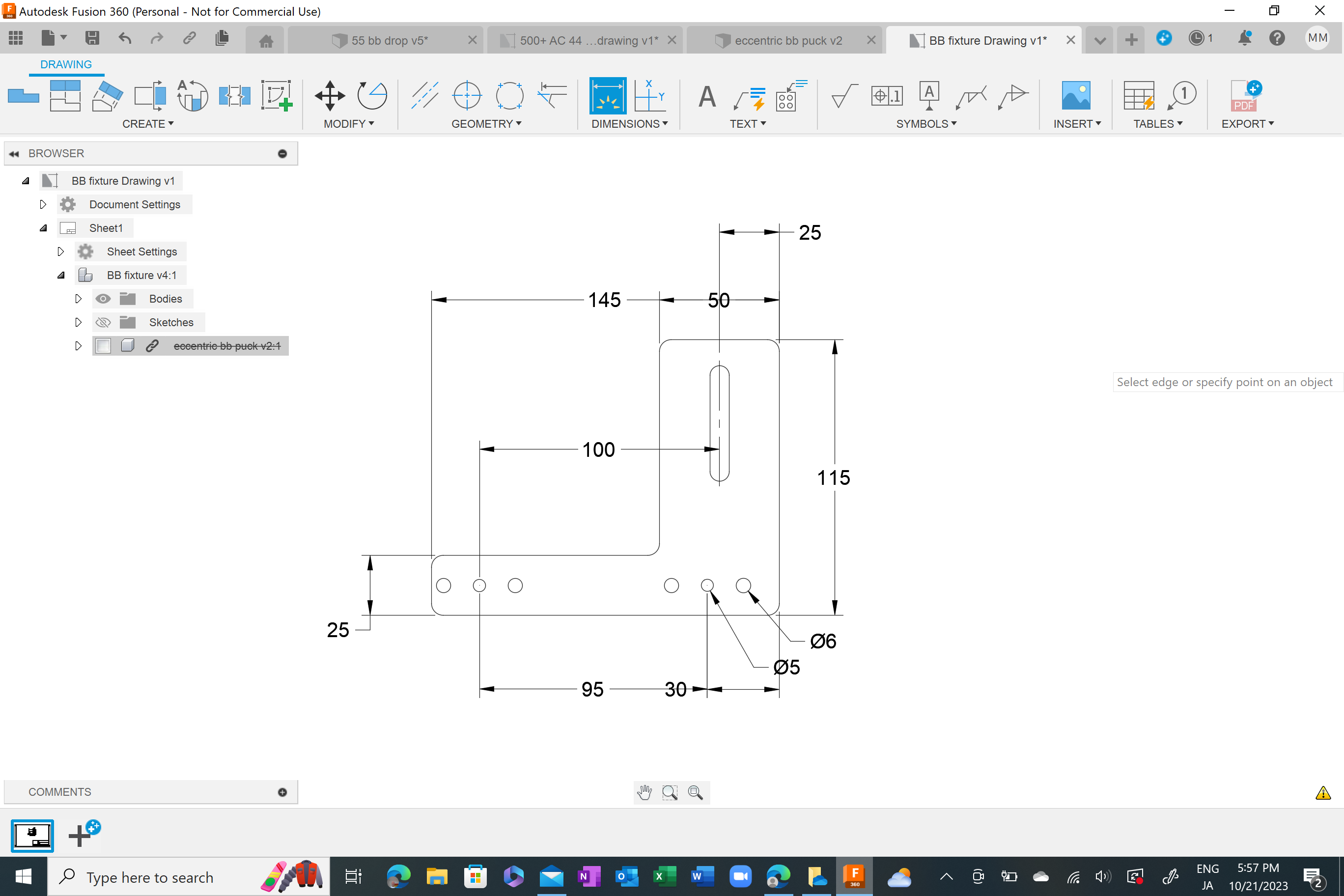
Below is an image of where the 3d model currently sits at and a screen shot of the 2d drawing of the BB tower with some dimensions. Here is the Chainstay_Mitering_Assembly_R1.PDF (179.1 KB) I got from Todd that I based my dimensions from. I’m surely not the only person who would like to utilize their fixture to do sub-assemblies, so, let’s dial in the design and get some made. As the order quantity goes up the price comes down, I assume.
Edit: I realized I forgot to offset the BB tower 5mm forward of the hole mounting location. Now I’m running into issues with how I constrained the hole locations. It’ll take me a few to re work the drawing.
I agree the yoke construction is more popular and needs new fixturing methods. The eccentric dummy is a great idea, but it throws off the scale?
One important note is that there are two versions of the Farr fixture out in the wild. V1 has “arrow” to help align the blocks, V2 has a tire dummy instead.
V1 uses a M5 bolt and has the blocks closer to the edge.
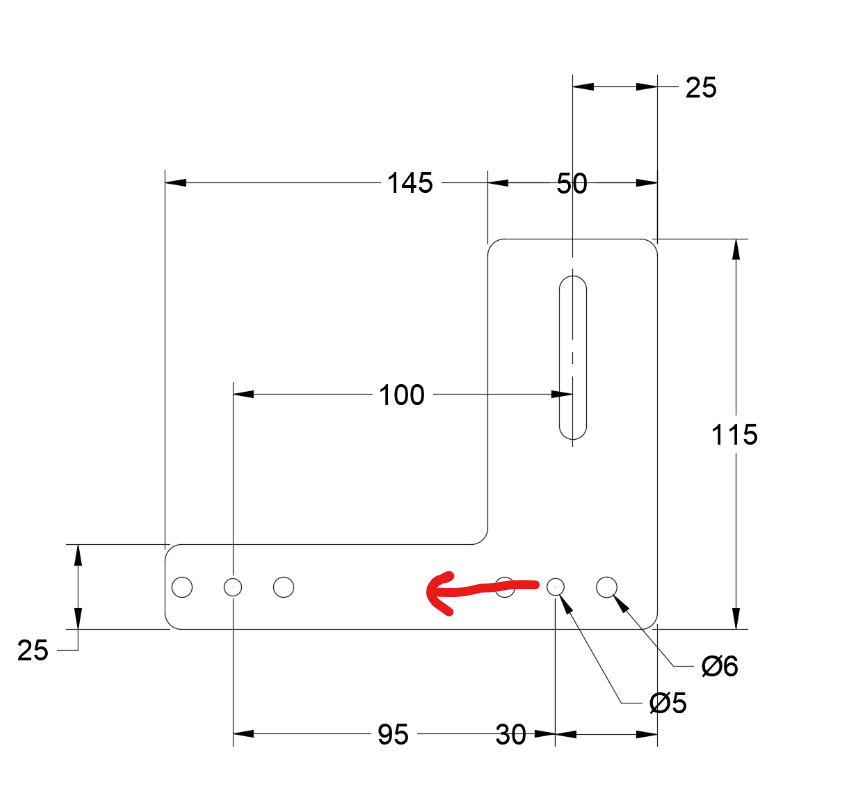
You will need to move the pin holes further back to make room for the BB dummy:
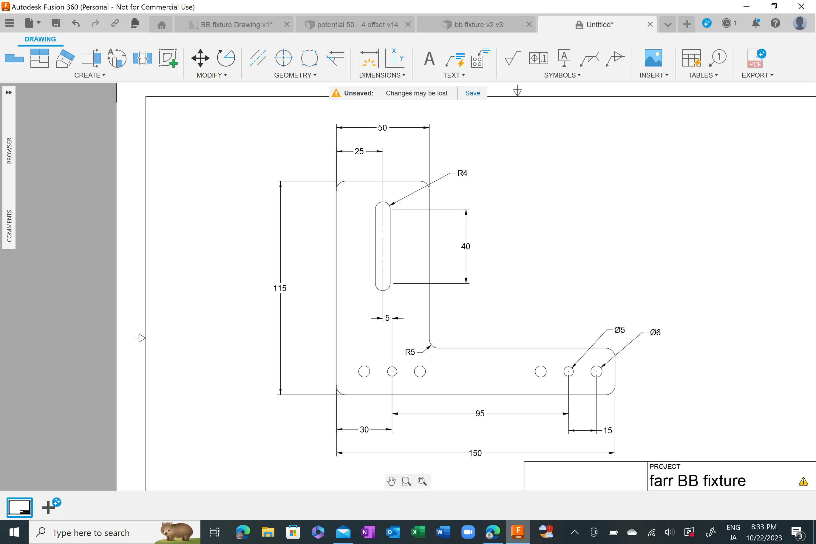
The model I am working on would be for a V1, that’s what I have. Slightly updated version shown below. I’m hoping to have a friend print this in plastic before I start wasting aluminum. Maybe the tower would be perfectly fine made of plastic?
This is true but in practice the eccentricity would be making up a few thousands difference if the cut wasn’t dead on. There would be some fussing around, but I think having some adjustment in the fore aft (X) of the BB would be beneficial.
The bolt hole is set back 5mm from the center of the BB, thats what the drawing that Todd sent me shows. The locating holes closest to the BB tower are for tacking the actual BB to the CS after a cut is made. The more rearward set of holes would be utilized for the chain-stay yoke with the dummy BB. Then swap out the dummy BB and attach the BB post for tacking on the BB.
Ah, I see the offset in your drawing. The 5mm should work. That 5mm offset will work fine with V2 as well, assuming you drill the 5mm holes for 6mm holes.
Makes sense. I was visualizing the eccentricity wrong. If the puck is “vertical” it should behave like normal. Good idea.
I currently have a “maker” license of Solid Works. This gives me full access to solid works for $70 a year. With the limitation of drawings having a water mark.
I very basic in the program but can make most simple parts.
I am thinking about switching to the free fusion 360 do to it having more support in frame building.
Can anyone give input on making the change? Is there any function the free version does not have?
I mostly make simple parts like dropouts, brake tabs, yokes. I usually 3D print and use send cut send for my parts
If you are planning on selling frames (not that frame building has to be a business), F360 is more attainable (you can get a 2 year startup license for free, or ~$500/year after)
F360 has the added advantage of community support (like this thread),
Both software will have annoying bugs and are functionally identical.
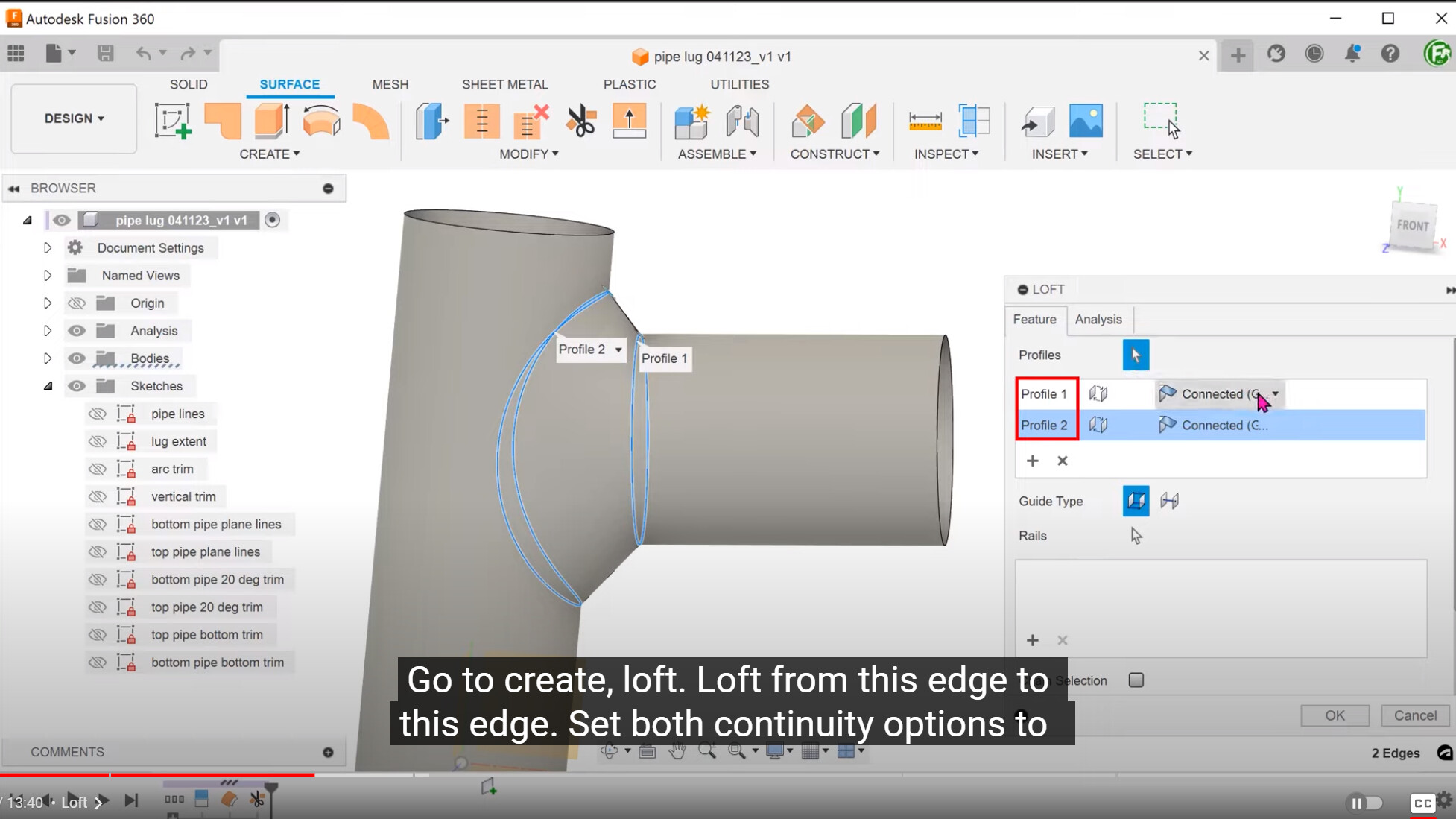
They show how to use surface modeling to create lugs. I think typically people (including me) use the good-old fillet and pray technique. I am slowly picking up on surface modeling techniques!
you can change the fillet settings between constant and chord length and get some decent results. Though I also use a lot of surfacing so it doesn’t scare me too much.
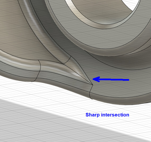
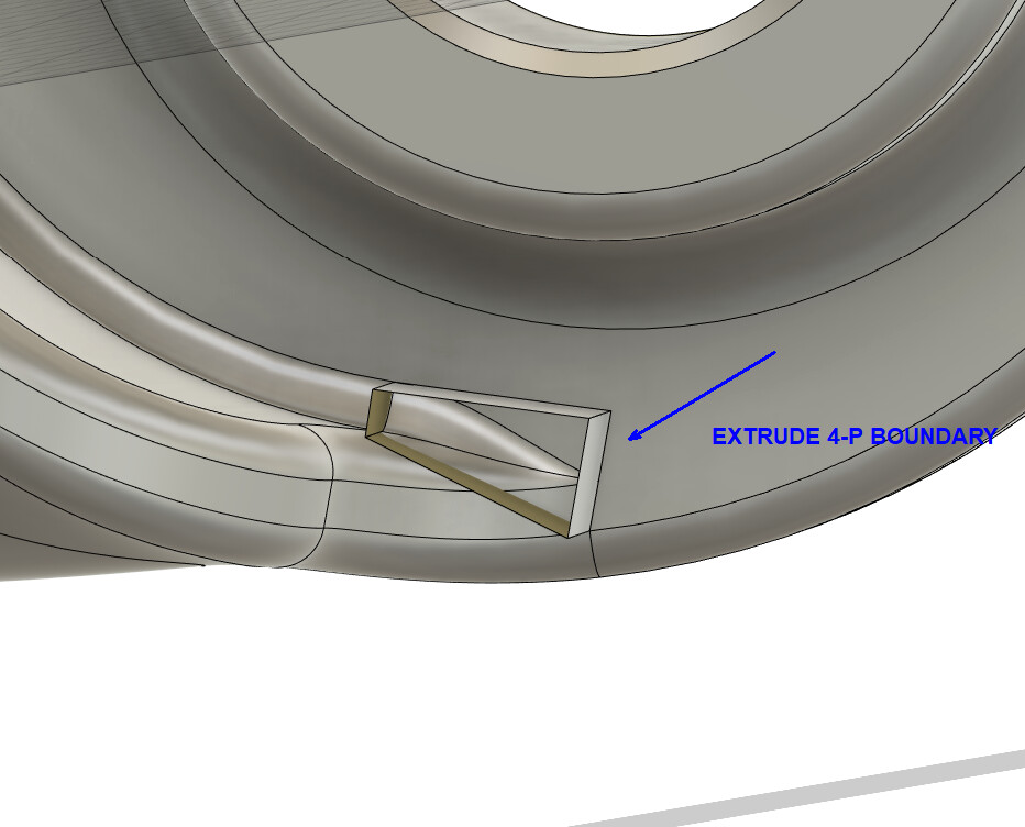
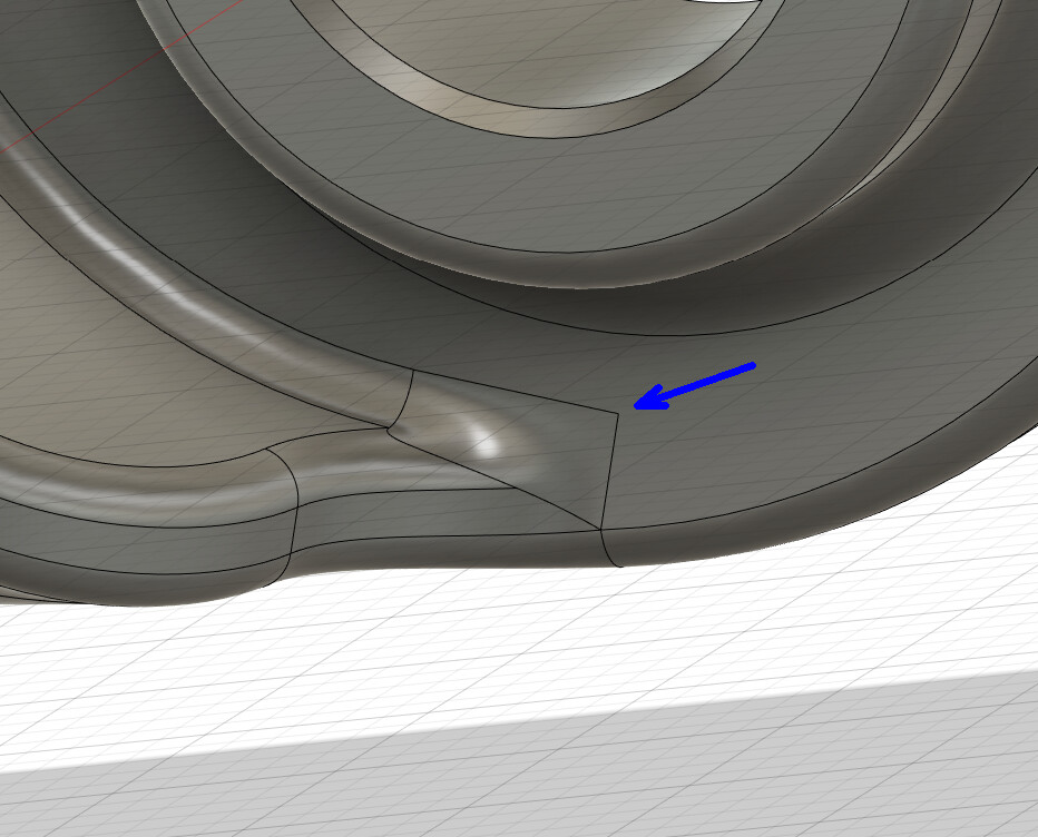
The real pro flow to not be scared of with constant chord length is cutting out a square patch (automatic four part boundary) at each problematic fillet intersection and blending the surfaces all back together
You inspired me to model my bike, a GT Avalanche an entry level bike with the triple triangle design which is kind of interesting but not good design for a frame builder with all the hydro forming. After 3rd attempt got it pretty close to the original. Thanks for posting the video.
I can send you the model if you are interested.