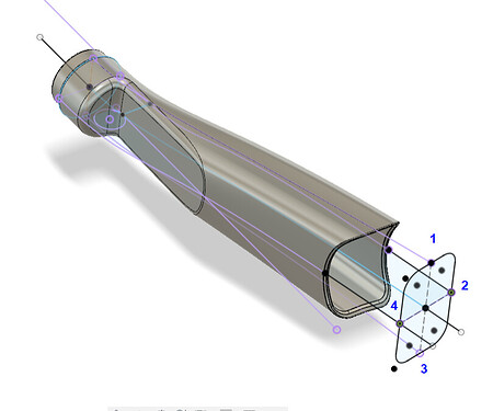
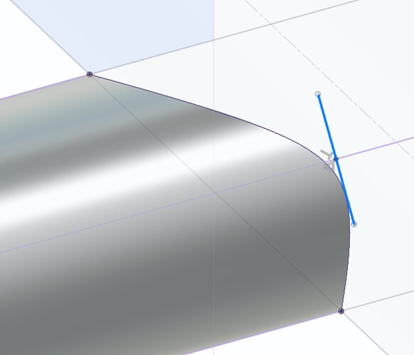
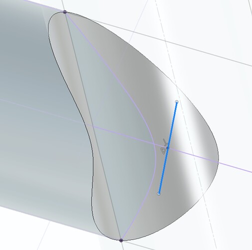
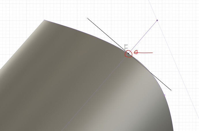
Could you point out which plane on which you’re creating the sketch to perform the Intersection Curve? Using a mix of your technique and Daniel’s I’ve got to the point of joining these geometries into a single line as noted…but I’m kind of lost on how to perform this step. Thanks so much for all your work putting this together!
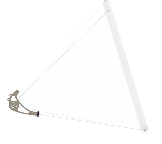
For the life of me I can’t figure out how to line up Paragon’s low mount (DR2032) dropout to model it up into a frame in Fusion. The major hurdle is that the dropout’s tab is offset from the axle centerline.
I created a centerline sketch to show where the center of the tab end should be located. I just don’t know how to move/rotate/joint/align the dropout body so the axle is on its axis and the tab is parallel with the chainstay centerline. The drawing above is my best attempt but it’s not precise. I just kept adjusting the angle until it looked close. But the point of using this software is not to be close but to be precise.
Thanks for any tips.
Nevermind. After walking away from the drawing for 10 minutes the solution came to me. I can apply the joint command to the face of the tab end and lock it to the point at the end of the chainstay centerline. ![]()
I have been drawing the chainstay sub-assembly as a separate file to make sure the dropouts are always clocked correctly:
Then I join that assembly into my frame CAD. I found this avoids mistakes and saves me time when I do different designs.
Hey everyone,
I’m currently working on modeling a 3D-printed yoke for a gravel bike, and I could really use some advice from the community.
The part will be printed using SS 316L, and I have a few questions regarding the design process.
-
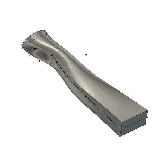
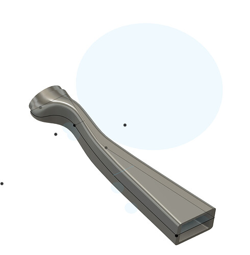
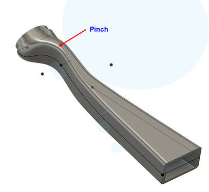
Lofting Control: I’ve been experimenting with lofting control, particularly with two approaches. The first involves using side rails and only an entry/end profile, while the second uses side rails and four profiles (entry/end plus two additional profiles along the rails). The first method results in some strange curves, whereas the second appears more promising. Should I consider adding more rails or profiles for better control?
-
Shell Thickness: Given that the yield strength of 3D-printed SS 316L is lower than that of CRMO, I’m uncertain about the appropriate shell thickness for the parts. Is around 2 mm the typical choice?
-
Interference Profile: If a CS bridge is to be welded to the inside face of the yoke, should I model an interference profile to accommodate this?
-
Fillet Edges: I’m aware that sharp edges can exacerbate stresses during 3D printing. What would be the minimum requirement for fillet edges to mitigate this issue effectively?
I would love to hear others’ insights or suggestions on these matters. Thank you in advance for your help!
Simple loft part:
4 x profile loft part:
RE: Lofting Control
When I worked through mine, I surface modeled the outer shape with 2 profiles (entry/exit) and 4 rails (top, bottom, left, and right).
To avoid the surface ‘pinching’ near the chainring clearance, it would be more controllable to overbuild the overall shape and then cut away the necessary clearance for the chainring.
For everything else, I used some guidelines in this thread: Need 3D printed pipe fitting? $1/g printed Monthly
But I’ll let the more experienced folks chime in.
Hey Kenyon,
Thanks for your reply and the advice. I should start experimenting with surface modeling, but as so many others I’m a bit afraid of it. ![]()
Can I ask what the narrowest section of your models is, and what section thickness you printed the parts in?
Great looking yoke! It should print well.
I do the second method. It gets the job done, but surface modeling is the correct way. I have to remind myself that a tire and chainring hide the parts, and no one sees them.
People use 1.2-1.7mm thick for 316 3D printed parts.
It depends on your printer. Some print software automatically downsamples the model, so it smooths all the edges so fillets are not necessary. For the external edges, I use .3mm. For internal edges, I use as big as possible to reduce stress.
Hi Daniel,
Thanks for your reply and advice.
I’m happy to hear that my modeling approach is not all off.
I tried using surface modeling, with a start and end plane + top, side, and bottom rails, but the design ended almost the same as normal solid lofting. I might need a couple of attempts before getting a hang of the surface environment.
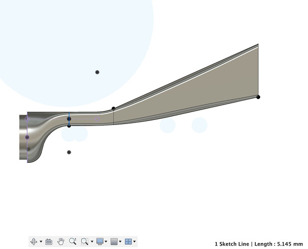
My next concern is that the pinch-point is only about 5,15 mm. I think it looks a bit thin and fragile.
Typically, the thin section ends up being 6-7mm thick. I have not seen thinner. I would give up some of your tire clearance or play it riskier with the chainring clearance. You can always space out the crank 2mm.
I’ll try that. Thanks for sharing your experience!
Hi Daniel! I’m starting out on fusion. I watched your tutorial on youtube for making a frame. Do you have any tutorials for cadding forks? Or any other tips? Or any resources for fusion 360 cadding? Thanks,
P.S. And like other general bike design conventions a beginner should know about.
Thanks,
@drewatkins720 welcome!
To answer your specific fork question, this thread has some useful information. If you see my post #26 (linked), you can download and reverse engineer the CAD file:
At some point I will make more Fusion video tutorials, but I am too busy right now! Reverse engineering someone else’s CAD is a great way to learn new tricks and workflows.
I am sure you have seen these resources as well:
PS. I moved this thread to the Fusion tech support topic!
Thank you, @Daniel_Y! This is so helpful!
Hi Daniel!
I’m having trouble opening the fusion 360 archive files in fusion 360.
Do you have any ideas why that might be?
Cheers,
Drew
P.S. All good! Figured it out. Thanks again!
Hi Daniel,
Can you help me with this frustrating niggle?
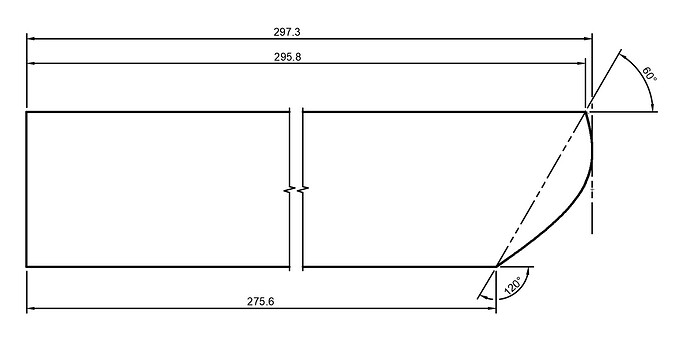
I’ve created a parametric frame model that works fine, but am having problems at the drawing stage. I would like to have a guide line on the tube cut drawings that is the rough cut length of the tube, ie the point of the mitre, not the base of the notch.
A sketch for using on the drawing has been created on the centre plane, with the intersections projected to it. I have created a guide line perpendicular to the tube centreline, but can’t get it to be associated (parametrically or otherwise) to the curve projected by the tube intersection.
This is what I would like, parametrically driven (This was just positioned by eye, nothing parametric or linked):
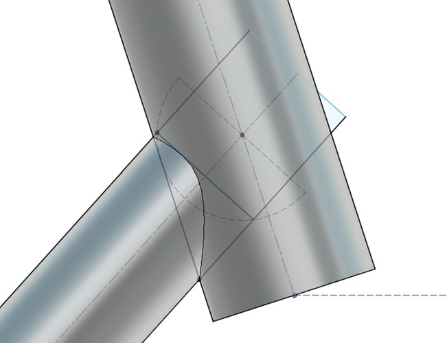
This is where I’m at:
All the best,
Dan Chambers
I have ran into this issue as well. I think the root cause is that projecting the miter creates a non-parametric line. I don’t think its mathematically possible to calculate the spline, which is why you can’t reference tangents.
I have also had these projected miters break the CAD, so I no longer use them.
This is the closest I could get:
- project miter
- make a point on centerline
- coincident constrain the point
- draw your perpendicular reference line
Still not exactly what you want, but close enough?
OK…woke up this morning with a solution. ![]()
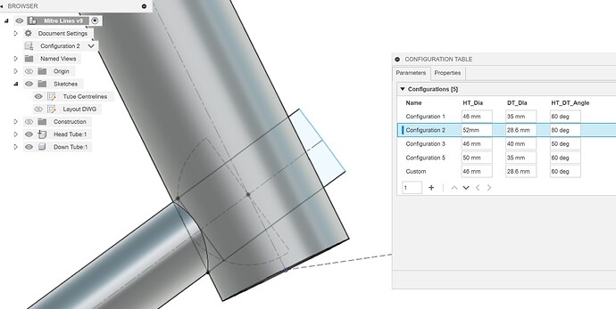
It doesn’t actually link the tube cut line to the 3D mitre curve (which indeed seems to be impossible), but calculates the same line in a different, basic geometry, way which can be parametrically driven.
This is just a simple ‘proof of concept’ test mode HT/DT joint, but it should work with the other two joints in the same way, so I’ll be applying it to one of my main models soon.
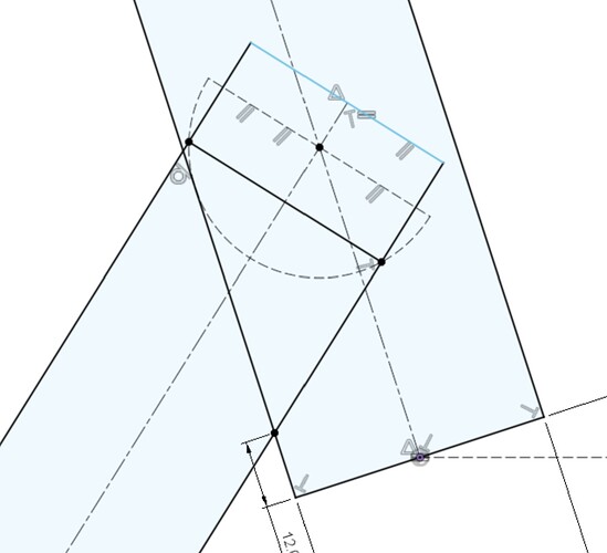
Sketch a semi-circle coincident with the HT diameter, centred on HT/DT centreline intersection, flat side perpendicular to DT centreline. (Goes screwy if it’s a circle, so don’t do that, but could perhaps be constrained in some way.)
Add points at the two DT edge intersections with this arc, then a (non-construction) line joining these two points.
This line will give the distance at which the arc of the mitre at its longest that’s not just placed by eye, and will move parametrically with any changes in angle and tube diameters.
…and then project it onto the layout dwg sketch for the tube to give something to dimension off on the drawing:
I also made some configurations using the HT diameter, DT diameter and DT to HT angle, and they all work (at least when the DT to HT angle is greater than 45°. Need to work on that).
Switch between standard specs, or add on a custom option and the drawings also update.
Now I just need to work out a way to parametrically force the tubes to display as horizontal on the drawing despite anglular changes in the model…Currently need to rotate the drawing using a driven dimension manually gleaned from the centreline sketch in the model.
Going to be something to do with Named Views, or maybe separating the tubes from the assembly as individual components before drawing. ![]()
All the best
Dan Chambers
