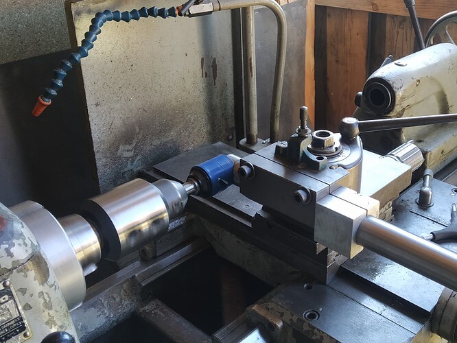
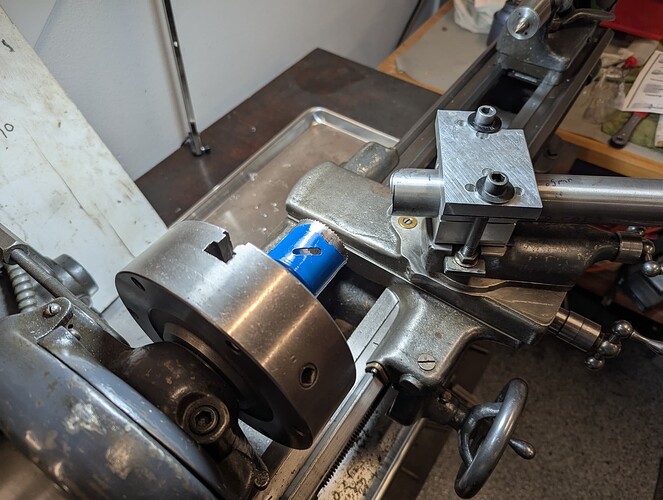
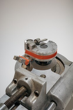
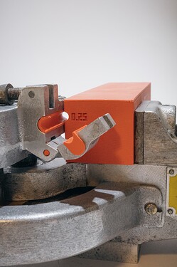
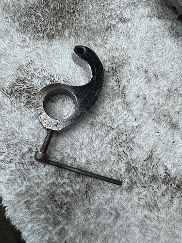
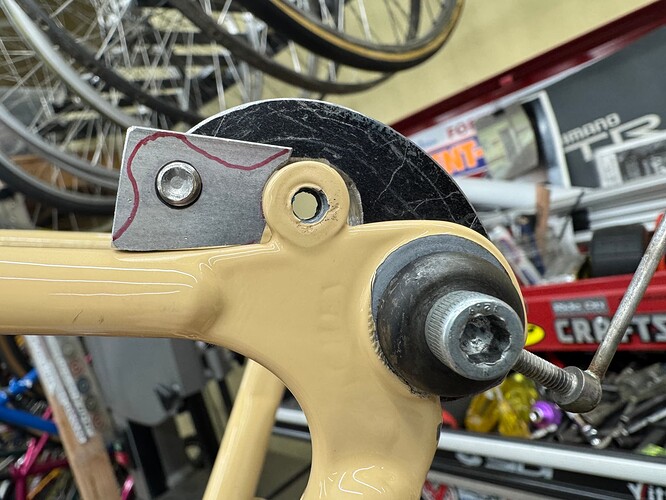
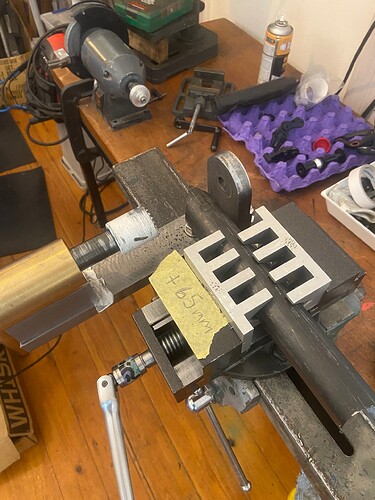
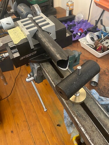
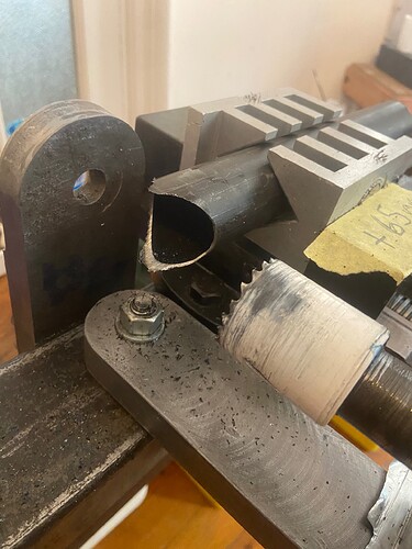
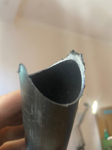
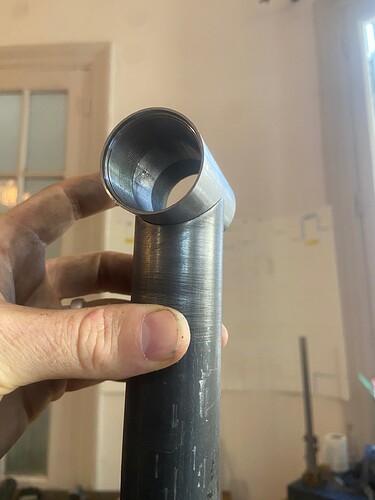
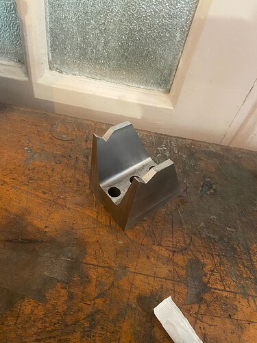
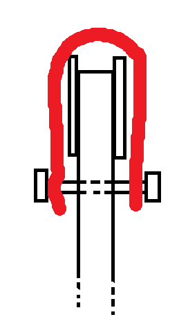
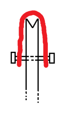
My lathe has a lot of backlash so the clamp is to lock the cross slide. You can‘t see it on the fotos but there are scribe lines at 0 and 90 degree. I have already had the broblem with the deburring:) but as long as I don‘t use the biggest diameter I can take the tube with the shim out and then deburr it.
Remind me of my first mitering setup before I had a mill a few years back
Same principle but on Multifix round tool holder , made a set of sleeves up to 38mm diameter.
carriage auto feed gave a really nice cut and rigidity was good but the cut angle was too finicky to set properly
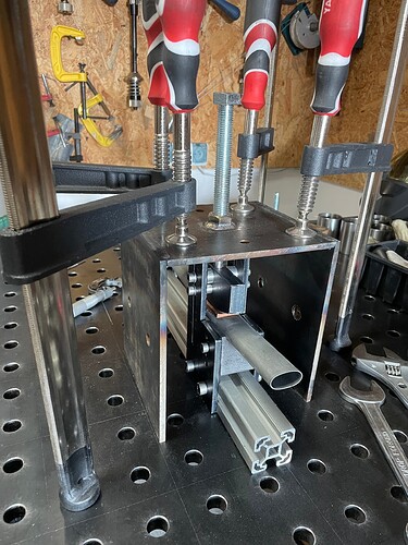
Another lathe tube mitering setup. Uses common frame blocks with spacers below the block for centering tube on spindle.
Right now I‘m building more tools then bikes ![]()
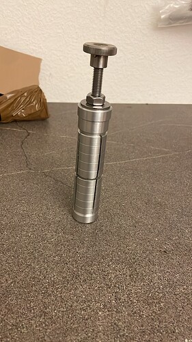
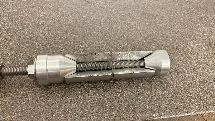
New heat sink for 31,6mm seat post:
The lower cone has a threat and the upper one a threw hole. When you thighten the nut the whole thing expands. The middel part is cut with a hack saw… the 4 parts hold together by a spring from a fork dust wiper. I Hope the thin spring doesent burn away while welding.
Sputniktool’s Jeff developed a third way. His jig uses two blocks, whose distance is determined by the desired tube length. For cutting, these blocks are held at a certain distance from the hole saw. So you don’t need the rather complicated dummy construction at the other end. Maintube mitering |
Clever tool! I think it falls under my method #1 (two blocks) though. At the risk of quibbling, I was only talking about how to clock the miters to be coplanar (or normal to the plane). His way adds the feature of setting the tube length for you, but that’s not a useful feature for me, because my frame geo spreadsheet doesn’t give me center-center measurements, only the cut dimension. As in where is the holesaw going to touch the tube. I’ve never been interested in knowing the c-t-c length of a DT, or even a TT if sloping (I only know the c-t-c of the horizontal equivalent), so I didn’t include the trig for c-t-c in my spreadsheet.
YMMV, but setting my trammel to a precision rule and using it to scratch a layout line on the tube is good enough for me, probably a tolerance of about 0.2 mm. Though I can make tighter tolerance if I’m willing to put on my Optivisor (magnifying headgear), I just don’t think bike frames benefit from more precision than that in the tube lengths.
For production, like making 50 identical toptubes, you can’t beat the dummy-tube method for registering the second miter off the first, while also setting the length. I haven’t seen the Sputnik in use, so correct me if I’m wrong and a Sputnik (or some other method) can top the dummy-tube style for speed in production.
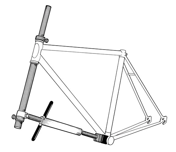
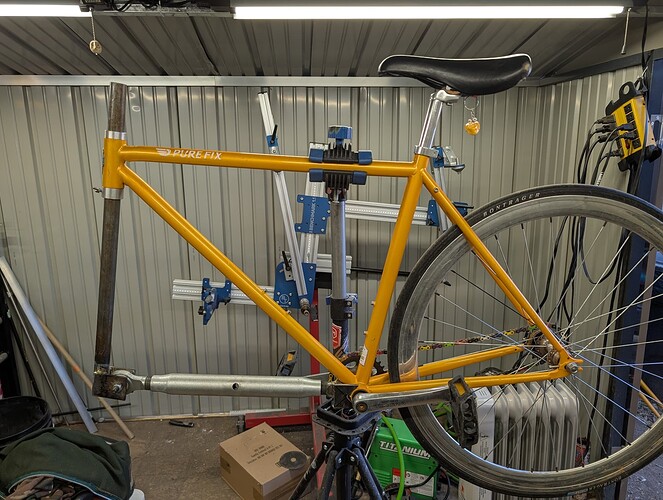
a friend hit a wall on her polo bike and bent the frame, normally that means new frame time but i recall fixing a steel frame i hit a wall with using a park tool way back in 2005 or so, and this is just a polo bike that doesn’t see any kind of street riding or anything. i figure it’s got some more playtime left if i can straighten it out.
however, the park hts-1 has been discontinued forever and i was only seeing parts of one for sale on ebay for $400 at the time, so went to harbor freight and made myself one.
it’s heavier and clunkier than the park tool version but it gets the job done
Nicely done! Looks like she hit the wall hard. ugh.
she did, but also these pure fix frames have to be hi-tensile steel. it kinda bent like it was made from playdoh haha
Park Tool was started by two guys with a Schwinn dealership in the 1960s. This tool wouldn’t have occurred to them if they sold lugged Italian frames with butted tubes!
Novice builder here. How to set the angle?
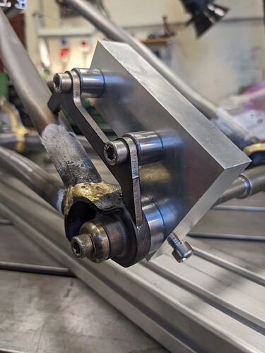
“Hmm I really need an iso disc brake mount jig. It’s only a plate with 3 holes in it, how hard can it be??”
Four hours later…
Nice brake bracket shape too.
3d printed die adapters (0.375 to 0.25in) and follow bar for my tube bender which is a parker 412. i’ve used this style of bender a lot at work and have been patiently scouring ebay for a good deal on one for a couple years. it paid off!
the follow bar is a thin (0.1") 3d print around a 1.5" aluminum tube. It’s really solid but eventually I’ll machine some more follow bars out of plastic or aluminum. this one does both 0.25 and 0.375 (just gets flipped upside down.)
I’m modifying a frame to take a Rohloff hub using the OEM2 torque plate. It requires a pin 39.9mm away from the axle on center. I created this little guy to hold the brazed on plate that will hold the pin:
Firstly I wanted to buy a small press to use the dimpling tool by @Daniel_Y . But than found that I have a “half box” in scrap that was a leftover from a side job. Only needed to weld one nut, turn screws’ tip and voila! The best thing about it is that it does not take space at all!
well I put one of these together.
ended up with an 80x40 rectangular tube with a wall thickness of about 4.5mm.
vise from chronos engineering supplies in the UK
jaws from andrés at ETB
machined the rest either myself or through a local shop.
threw some test cuts through a piece of 38.1x0.9mm plain 4130 tube with a 38mm Sutton tools variable pitch holesaw; full speed on the clapped out 600w power drill, cut took about 10 seconds.
seems pretty great. needs quite a lot of fettling to be beautiful and functional but the bones are there, also likely be a much nicer cut if I go a bit slower ![]() , but good to know that it is its stiff and capable…
, but good to know that it is its stiff and capable…
cut quality I think can be improved by just slowing down a fair bit;
straight off the tool;
and after a quick pass with some 120g
while I was outsourcing some of the bits, I also got one of these made;
this should let me mount a dummy axle at centerheight in the tool, and along with some clever vice jaws, cut the BB end of the chain stays, aswell as the ST end of the seat stays, (the latter will also require moving the pivot arm into a “ZY” orientation) buy given those mitres are the slowest by hand ( for me ) im hoping the setup will be worth it.
doing my best to contribute some WIP here, shout out to everyone else doing the same, its appreciated!
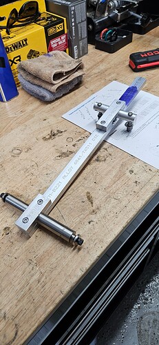
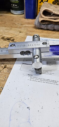
Just made a canti brake jig after having to cut off a set I didn’t put in the right location. Stops for 26", 650b and 700c. I’m going to add holes for caliper brakes (49 and 57mm reach). The brake post holder rotates to be able to set the posts perpendicular to the stays. It has holes for 75mm and 85mm post spacing. I had laid out 80mm as well, but realized it would take out too much material. Dummy axle from Alex Meade. I want to figure out a way to hold CS bridges with it.
For the bridge, add a V shape holder at the end so the bridge can fit (V shape so it fits multiple sizes), then you can hold it via a strap, like a leather strap or even a rubber one if heat is not a problem (tig?), a pass thru bolt will make a good strap attachment point
Take a look at this highly technical CAD drawings
