Great idea on the sliding miter gage!
3 Likes
Thanks! Gonna update yours now? ![]()
1 Like
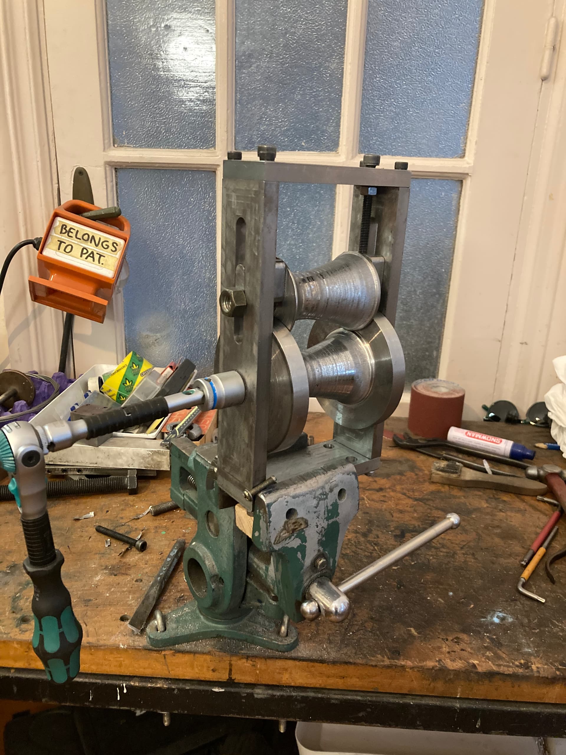
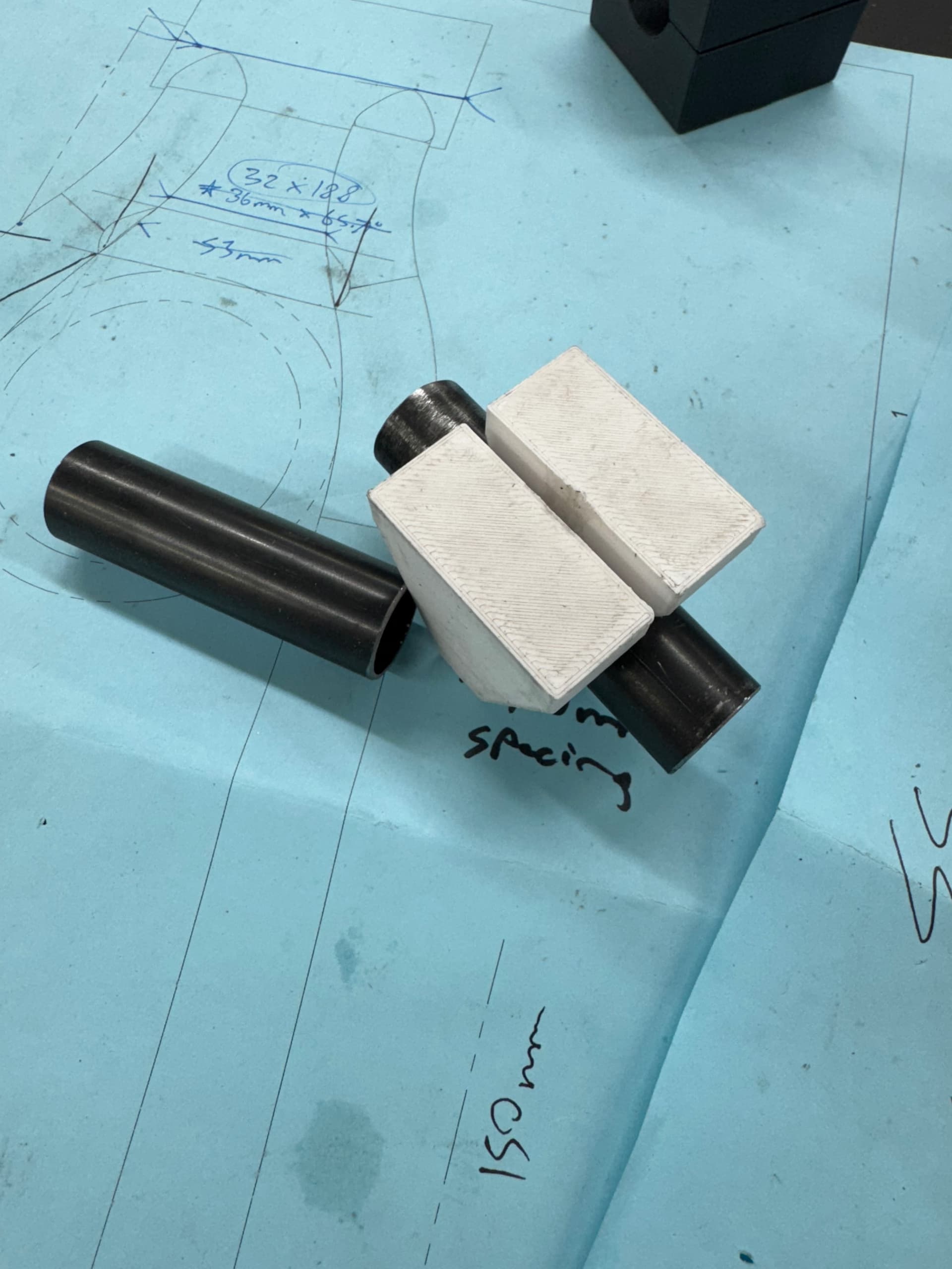
after dreaming of ludicrous teardrop downtubes and battling through either dealing with pre-made options which are thicker than id like, or struggling away making my own a few times, I saw Clive Gillum pull this little number out of the hat; way too simple to be effective, I thought; but I was wrong. he’s making tubes the shapes he wants with it.
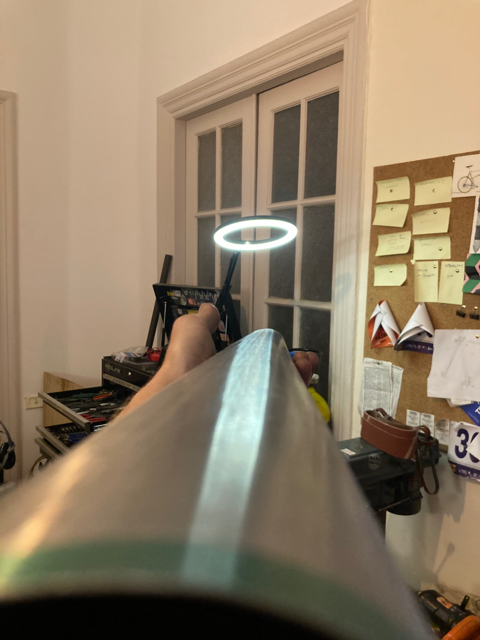
after asking him about his setup a bit I whipped up the supersize-me edition, and rolled this MASSIVE downtube over a few passes with the help of my really tough girlfriend (she didn’t tell me to say that).
awesome.
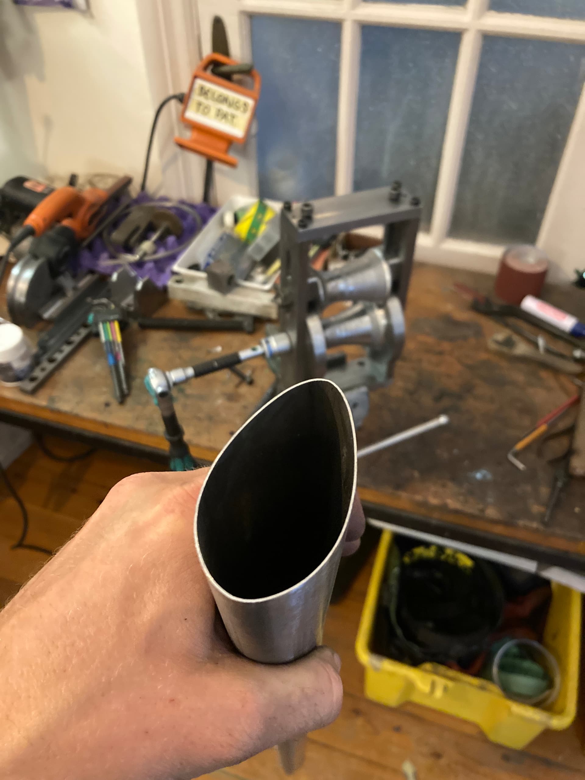
the tube looks like its pretty good, it cats-eyed way less than I thought it would. and its come out at least as straight as it went in, and no dents or twist.
the starting tube was 0.75mm wall ~51mOD straight gauge, the finished shape is 33.5 x 65.5, probably have to lose about 60mm of either end but there’s plenty of length so no worries there.
edit, correction made, thats a 0.75mm wall tube, not 0.8 as originally stated.
29 Likes
Really impressed by your tubing roller. Care to share any details about construction? Thanks, Daniel
sure thing!
here’s a step file you and anyone are welcome to, subject to this licence; Deed - Attribution-ShareAlike 4.0 International - Creative Commons (I, Patrick Crowe Rishworth being the original creator) {TLDR, use and modify/reshare this for whatever purposes you like, but attribute me, note your changes, and share under these same rules.}
pats tube roller v1.step (208.7 KB)
it admittedly is a notably rough first pass;
I had the four ‘frame parts’ cut by a friendly local cnc shop but would be easy enough to make by hand from some flat bar, the frame is held together with a few M6 cap screws in each corner but could simply be welded.
each roller was rough flip-cut on a cnc mill (because of some pretty bad miscommunication and a somewhat hilarious language barrier) and then finished on a manual lathe (including a last pass with a power file for some texture), and simply runs on an m12 bolt. the lower roller has an m6 grub-screw that grabs onto the bolt so that the bolt head can be used to drive the roller via socket, and that seems to work fine™️. the driven bolt just runs in a 12mm hole in the frame, so making up a proper shaft and pushing in a bearing here would be a nice improvement.
the floating roller is held up only by the tube, and pushed down on each side by an M8 screw. very basic setup, so far entirely functional.
it would be nice if the axle bearing blocks were captive on the end of each m8 bolt so they could be used to raise the roller too, which wouldnt take much to do, again, also, a nicer bearing surface wouldnt go a miss, but none of that has proved necessary yet.
anything else you’d like to know?
edits for clarity,
p.s.
the m8 push screws for the roller each simply have a nut threaded on them inside the frame which pushes against the “roof” but threading the “roof holes” would maybe be better.
the “walls” on the lower die were a complete waste of time with this profile
the glossy surface on the rollers was caused by use, they’re some sort of free cutting mystery metal thats super soft. for a starting tube of this diameter I think wooden rollers might be ok, and would be super easy/cheap to make , though the drive roller might need a drive pin rather than grub, to stay locked to the axle, and the surface may not have lots of traction on the tube.
4 Likes
So generous!! Many thanks. I will enjoy digging into this. Daniel
1 Like
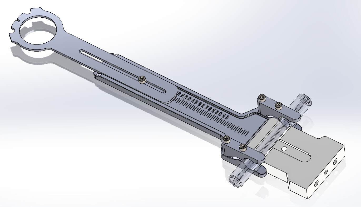
I was frustrated with the tube bending options for tight radius bends in 0.5-1” thin wall tubing for cargo bike rear triangles, racks, etc. I struggled with getting accurate and kink free bends with JD2 type benders, even with a mandrel. So, I did what any sensible person would do, and developed my own. Currently it is powered by a garage door motor and drill battery, but I’ll need more gear reduction for 1” steel (Is anyone aware of a reasonably cheap gearbox that can do 100+ Nm?). The motor seems maxed out with 3/4” aluminum. But there is no sign of issues with the 3D printed dies. There is a limit switch to stop at the specified bend angle which works really well to get repeatable angles. Quick video here: https://youtube.com/shorts/FMQGglIZcas
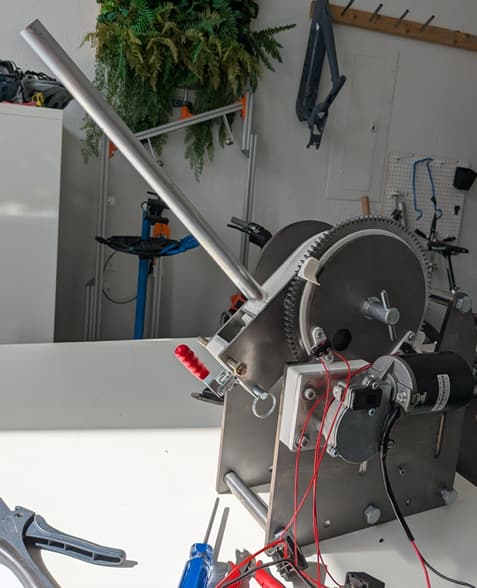
Next steps are to bump up to a higher torque motor/gearbox, improve the angle setting stops and make the pressure die adjustment faster and maybe tool free.
20 Likes
Throwing out motor ideas and see what sticks:
- a winch, most cheap winches should have enough power for your application, I am using my truck’s 12k lbs winch to unstuck seatposts
- the motor from a gate, those motor have enough power to move a wrought iron gate, they should have the muscle and reductions and should be fairly cheap
1 Like
I like the winch idea. I think I’ll rob the motor and gearbox from a harbor freight winch and that should be plenty of torque. I could even use a nylon rope instead of spur gears like this guy: https://www.facebook.com/profile.php?id=100063727412569
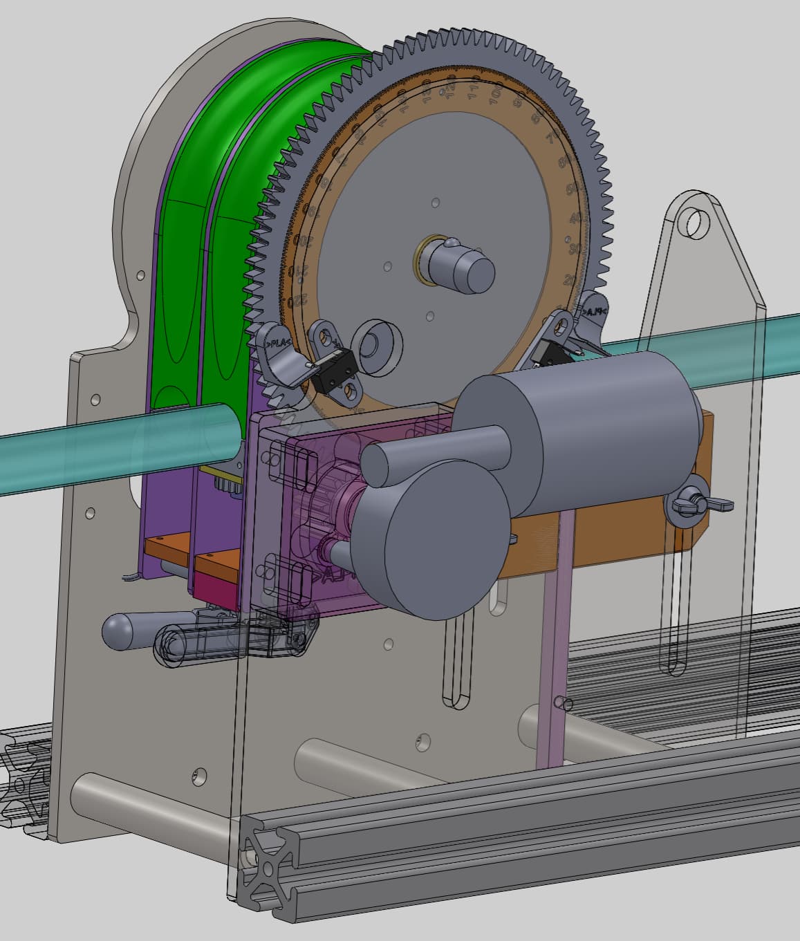
I also want to add some features to the 8020 rails in the CAD model above to measure distance between bends. Once the “bend deductions” are known for a given tube diameter/wall thk. It should make for accurate multi bend assemblies.
1 Like
I wonder if a pipe threader has enough power to do the job: https://www.harborfreight.com/12-amp-portable-electric-pipe-threader-62203.html
Quite possibly. It doesn’t have any torque spec listed though, so the winch is a safer bet, as it has specific max ratings depending on how much rope is on the coil.
1 Like
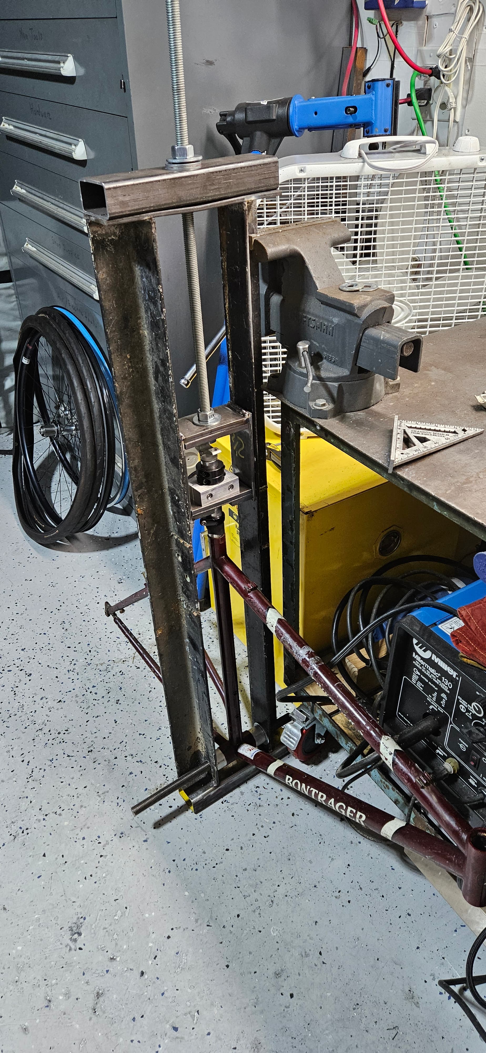
I bought a bike with a stuck seatpost, so took it as a reason to build a puller. Unfortunately, it didn’t budge. I soaked the seatpost with penetrating oil for days beforehand. Maybe I needed heat? Anyways, melting it out with lye instead.
2 Likes
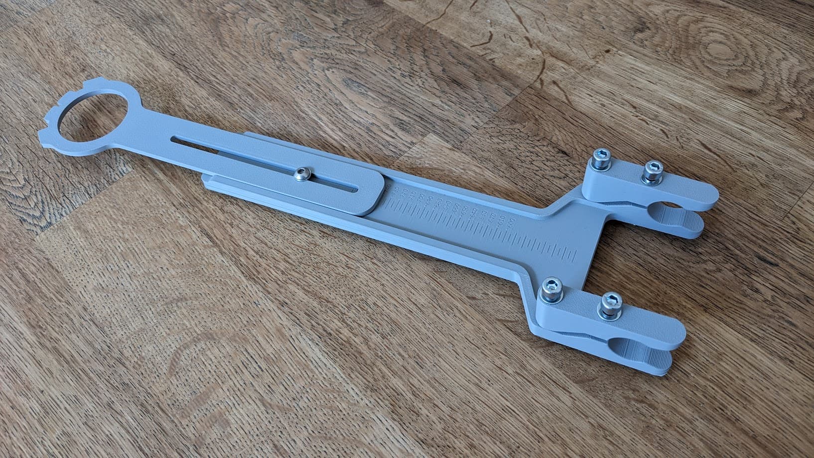
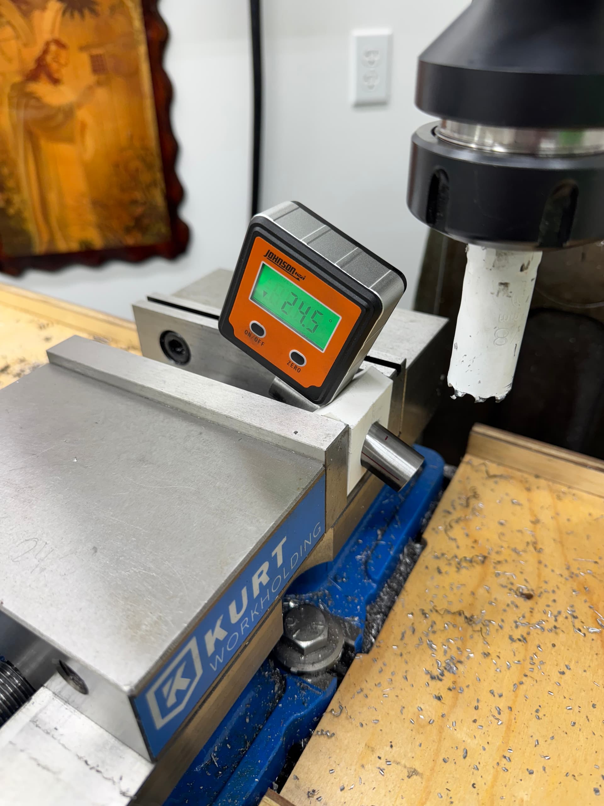
While I was waiting for welds to cool I fixed up this flat mount jig and some flat mount bosses for a 160 rotor. All manual machining.

8 Likes
Over the years of walking my dog to the nearby park I have collected dozens of gold balls, I knew they would have come in handy!
Last weekend I had some time to fix two of the handles that I deal with mostly everyday and that didn’t had a knob
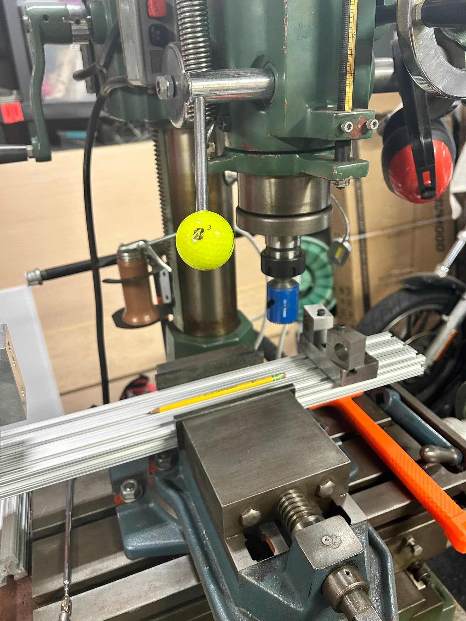
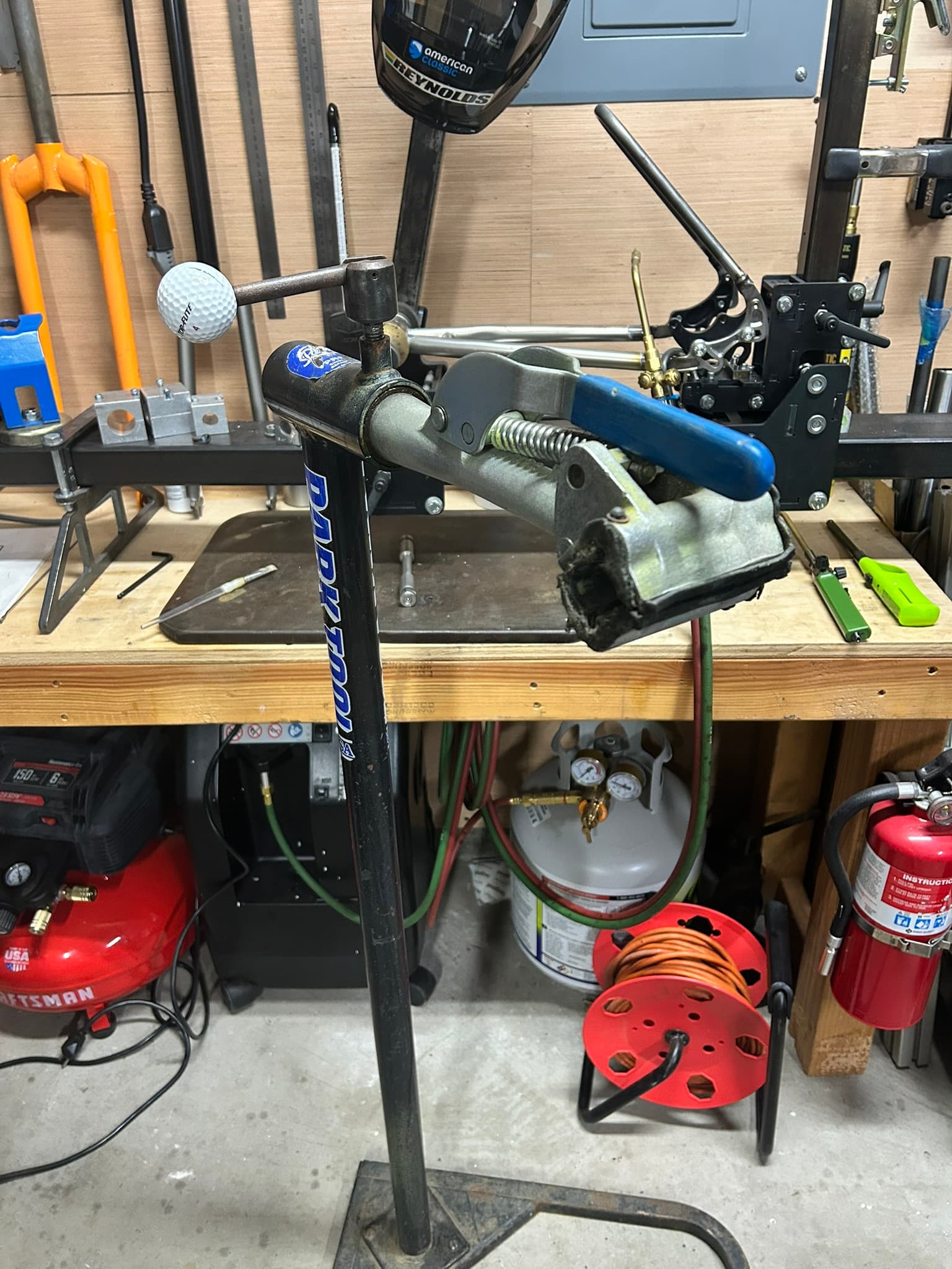
Note the 1995 Park Tool stand that still does it’s job, just needs some TLC. Great for quickly moving the frame around while brazing/welding
8 Likes
@wvucyclist I did the lye trick to remove a quill stem from a seized steer tube.
But I let it soak for 3 days or more and was able to cut off most of the quill stem. Just had what remained in the steer.
Not quite sure how you could soak that without a large container, which I would avoid.
if you seal over the “top” ( eg with a plastic bag and a layer of duct tape, being sure to cover the seat tube slot..) , and turn the frame upside down, with a little care you can pour the lye “down” the seat tube from the bb end (sometimes through a drink bottle boss) and dissolve it from the inside, using the seat tube itself as the ‘container’. do this above something to catch the spillage; inevitably, it’ll leak,
1 Like
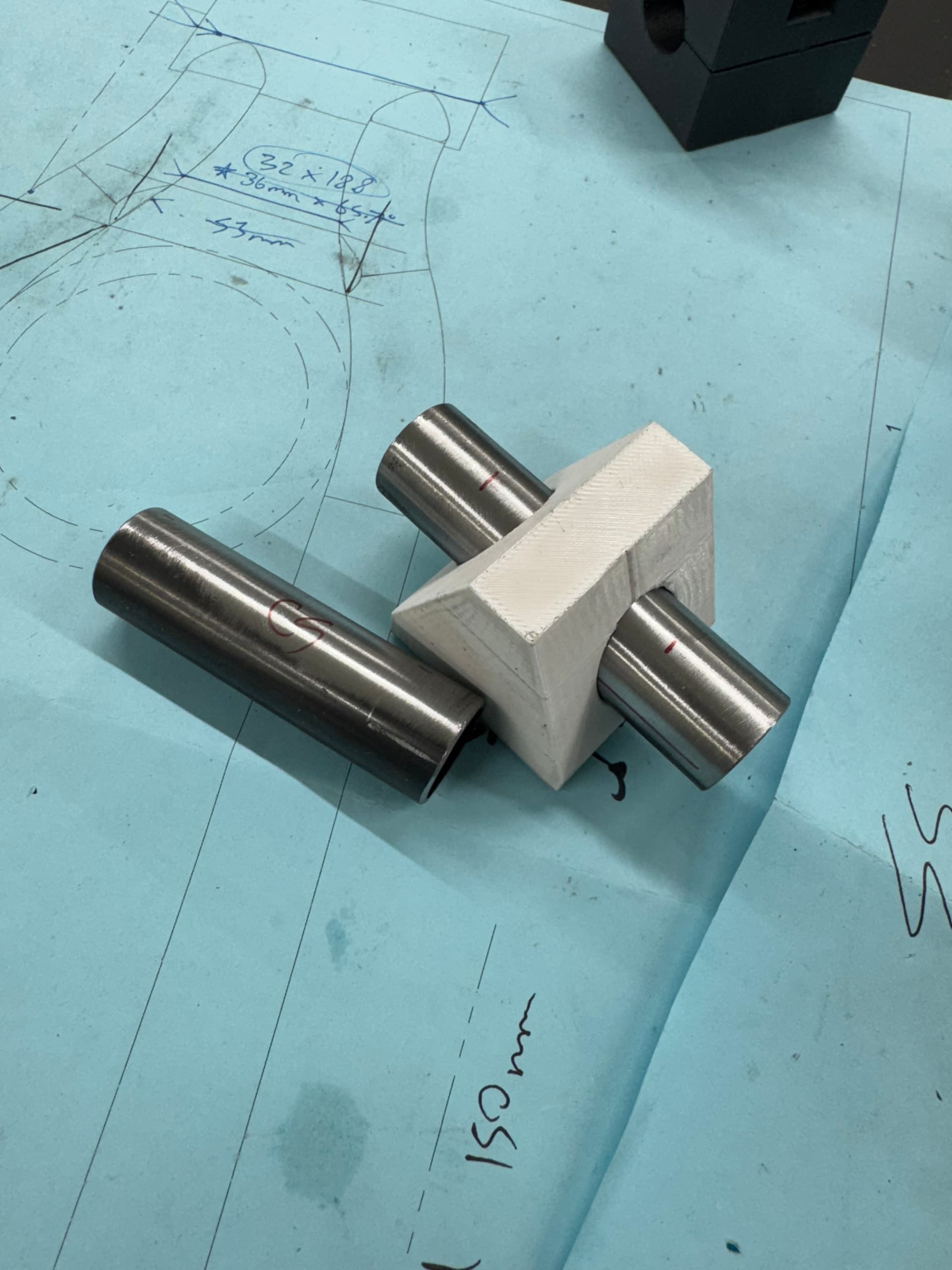
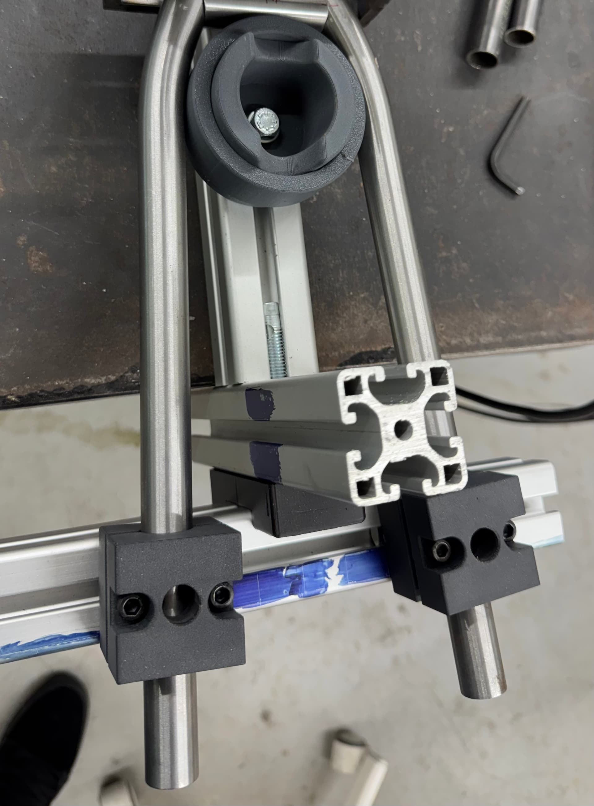
Man I forgot how incredible this thread is! Here are my contributions of 3d printing helping for quick custom fixturing. My favorite is probably my bridge clamp. Holds the clocking of the tube with the in-built light clamping, easily released with a flathead screwdriver. Last photo shows easy clamping of SS tubes for fixturing/ tacking SS bridges. Also, a sliding wheel dummy that is the tire diameter, with a removable ring of “desired” clearance OD. Makes tire clearance a no brainer, cus I’ve messed that up more times than I care to think about. Lol
edit: happy to share CAD files with anyone who’d like them.
8 Likes
Great Idea with this wedge block! I might “take that as an inspiration” (shamelessly copy it…) ![]()
1 Like
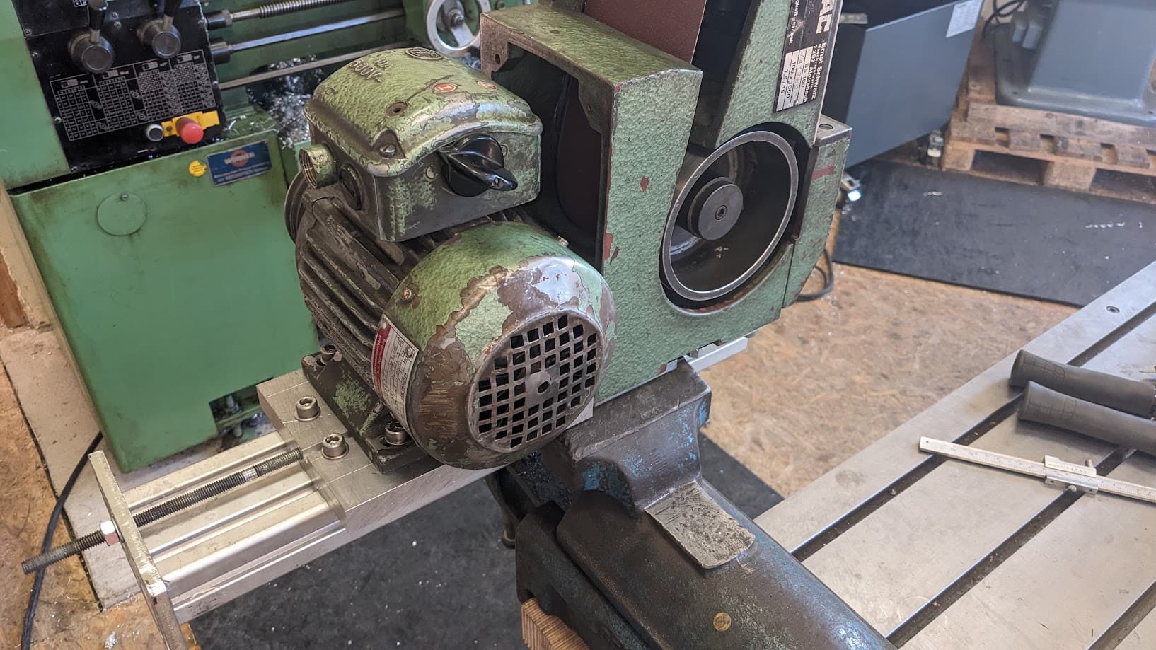
Not really shop-made, but rather shop-overhauled and -reconfigured ![]()
Got myself an old german made belt grinder “Mafac BS100”, pretty run down but very affordable. These can go for as much as 1000€ when in good shape!
In normal config they look like this:
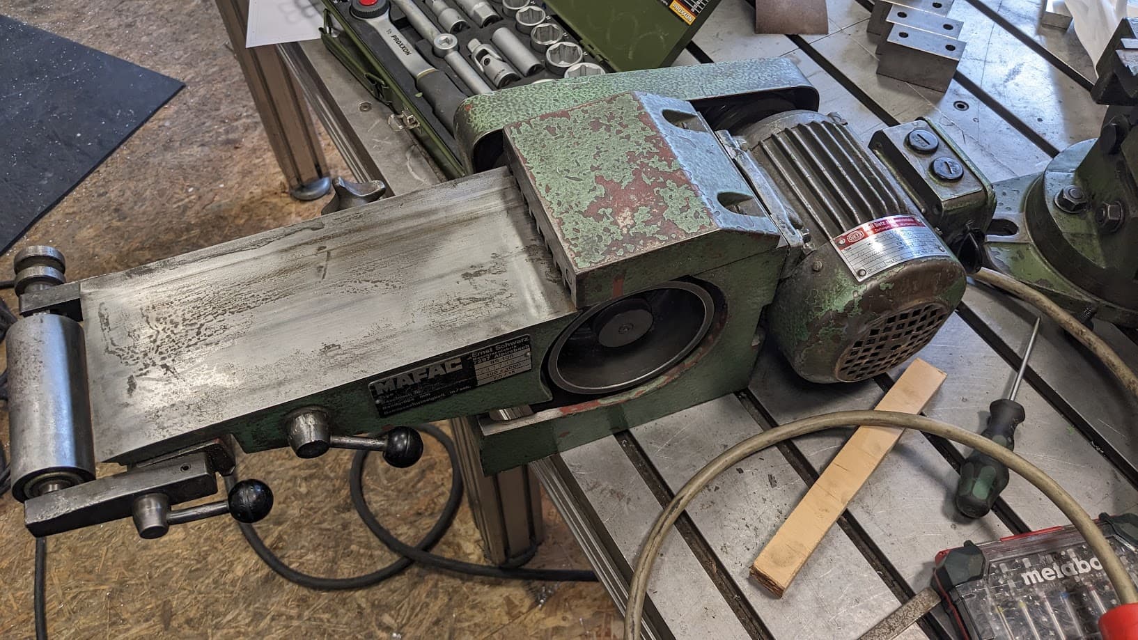
It’s about 40 years old, the bearings have seen better days and the table has lost quite some material over the years and become quite uneven
Also the threaded holes in the casting holding the motor were stripped
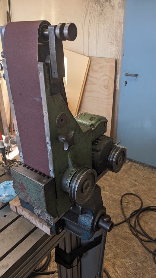
First, I took 2mm off the top surface and bolted on some stainless I had in the shop, then decided it would be much better if the whole arrangement was upright, so bolted the grinder and the motor to a piece of alu extrusion, including a belt tensioning feature ![]() Now just waiting for new (longer) v-belts to arrive!
Now just waiting for new (longer) v-belts to arrive!
8 Likes