WORK IN PROGERSS. Need to transfer all photos
Why Learn Fusion360?
- Solve problems from the comfort of your armchair
- Prototype complex 3D designs: dropped chainstays, tire clearances, etc..
- Complete design freedom:
- full suspensions, unicycles, cargo bikes, triathlon bikes
- Parameterized designs:
- update base sketch, or parameter table, and the entire model updates automatically
- 2D drawings can automatically update as well (sort of)
- Knowing 3D CAD opens up a lot of doors:
- Design fixtures and tooling
- 3D printed parts
- CNC workflows
- It’s free (sort of)
Step 0: Get your ducks in a row
It’s hard to design something if can’t visualize it, especially if you are learning the tools at the same time.
I do a lot of hand sketches, bikeCAD, holding parts in my hand, etc… to help visualize how things come together before I open up CAD. The brainstorming phase takes most of my time.
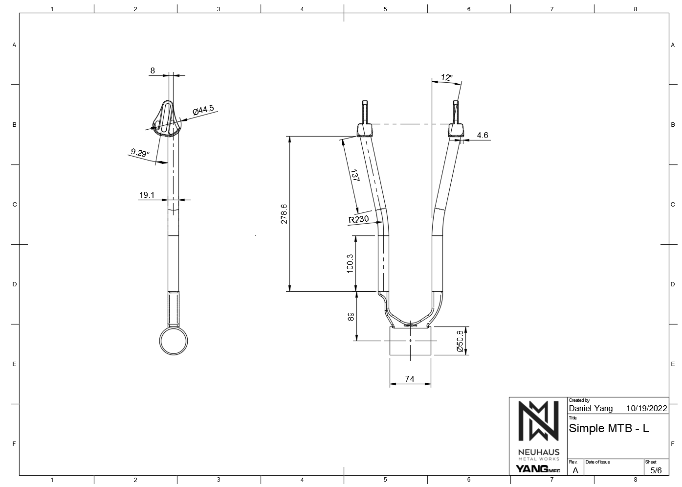
- Gather your 3D parts:
- Dropouts
- Headtube
- Yoke
- Understand the standards and dimensions of your design:
- 29x.2.6 tires with 6mm clearance on each side
- 754mm diameter, 66mm wide
- Chainring and Crankarm clearance
- Fork crown clearance
- 29x.2.6 tires with 6mm clearance on each side
- Have a general idea of how the tubes are going to connect
- what radius are your bends?
- what chainstays and seat stays are you using?
- Will the seat tube or downtube need a bend?
Final Comments Before Beginning:
- This tutorial is going to require some basic understanding of Fusion360
- See resources.. (TODO: add links to resources)
- Resist the urge to click buttons until you have read the entire step of the tutorial
- While creativity is always encouraged, I suggest completing this tutorial verbatim first, then designing the 61deg HTA frame of your dreams
- CAD Download Link: (TODO: link model)
- Companion video, coming soon, maybe.
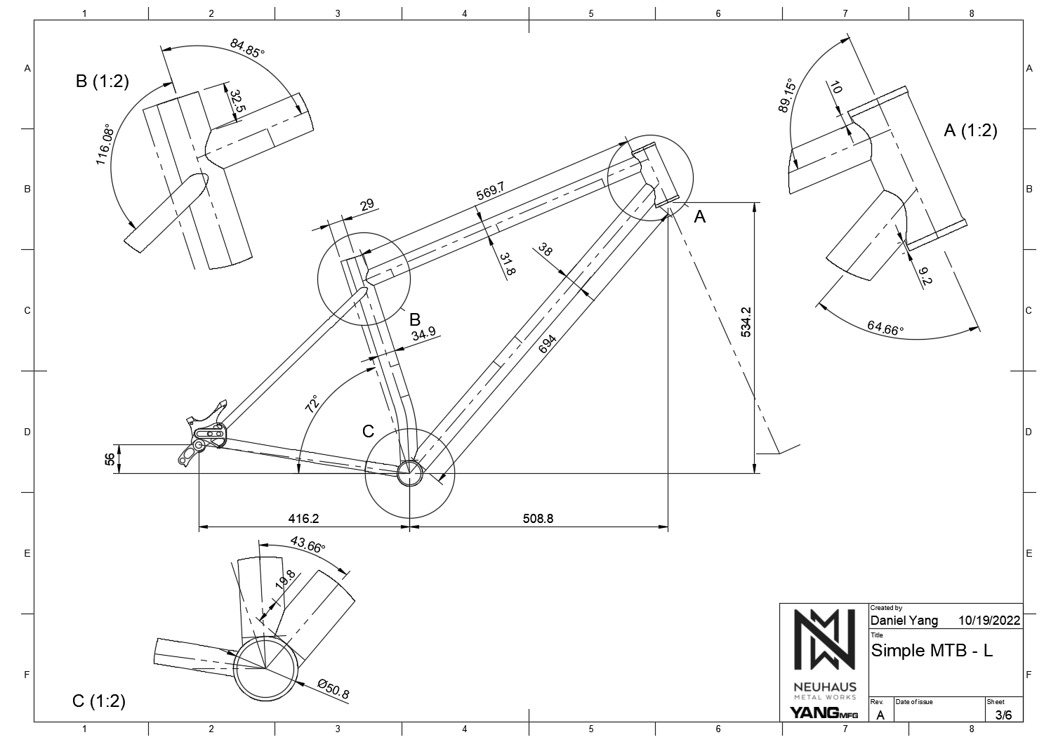
Step 1: Base Geometry Sketch
Start with the seat tube:
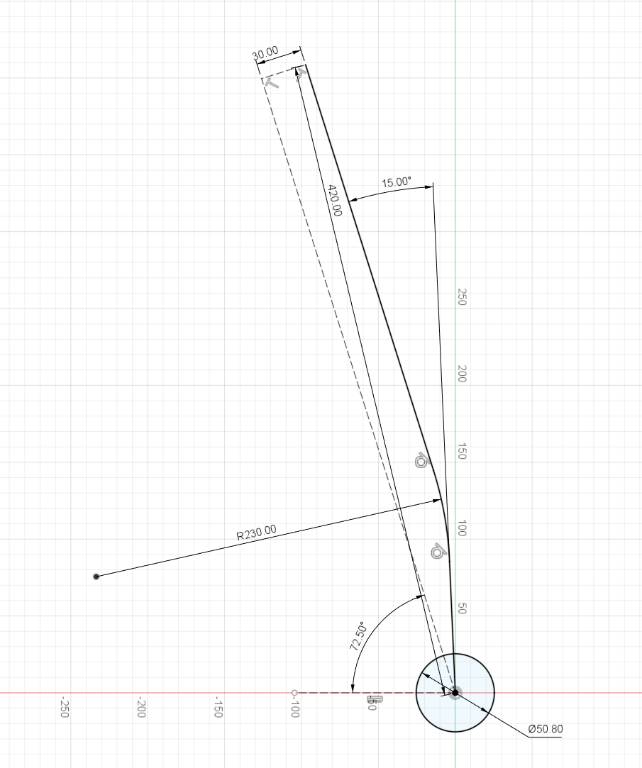
Then fill in the rest:
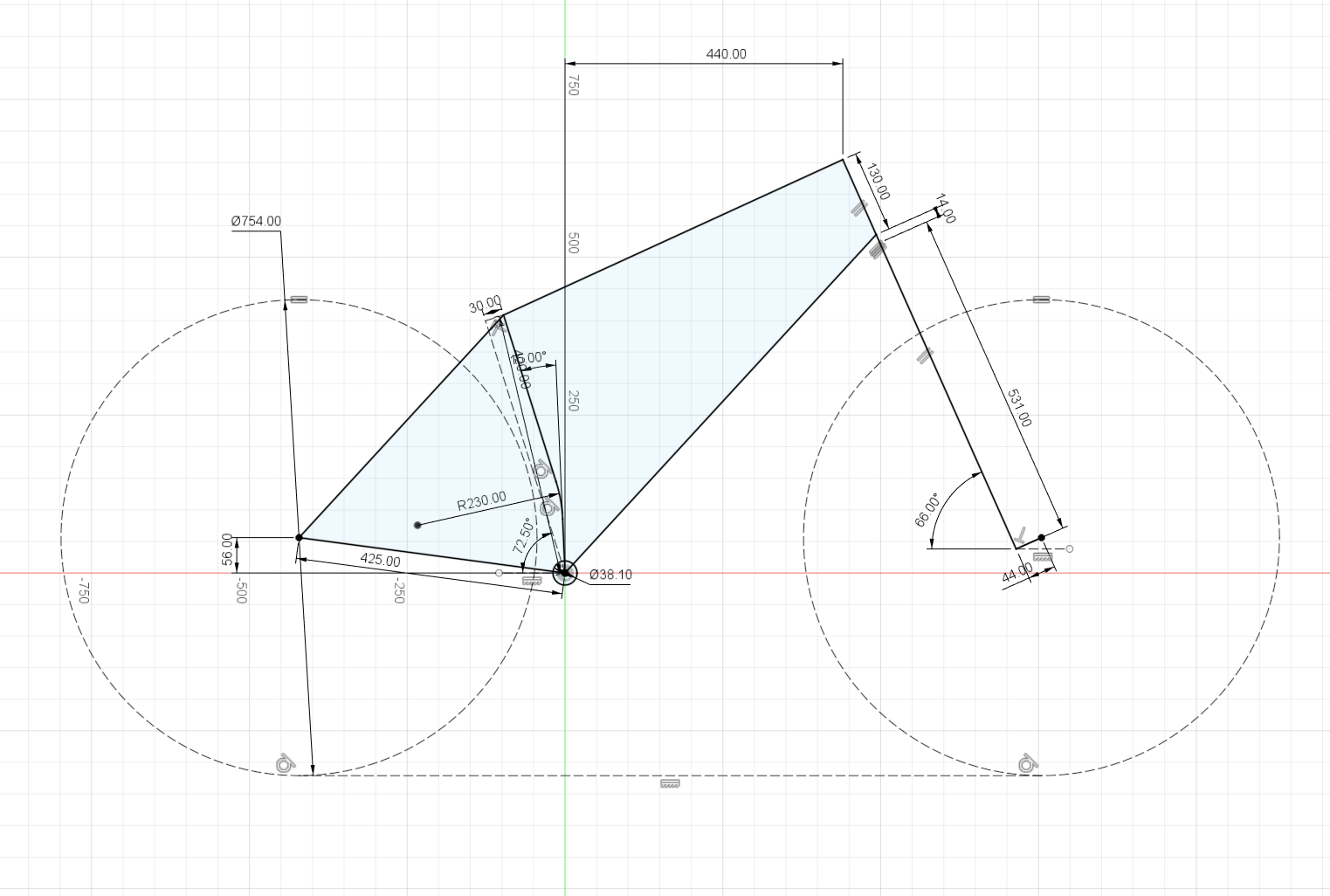
This is the sketch that everything else will be linked to. Do not draw your tube centerlines in this sketch. That will be step 2. Name this sketch “ Base Sketch”
Tips:
- Please don’t deviate from this example yet, it might lead to complications later
- if you did everything correctly, your entire sketch should be black, meaning that it is fully constrained
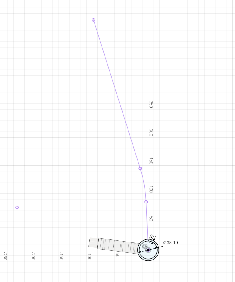
Step 2: Draw the Centerline Sketch
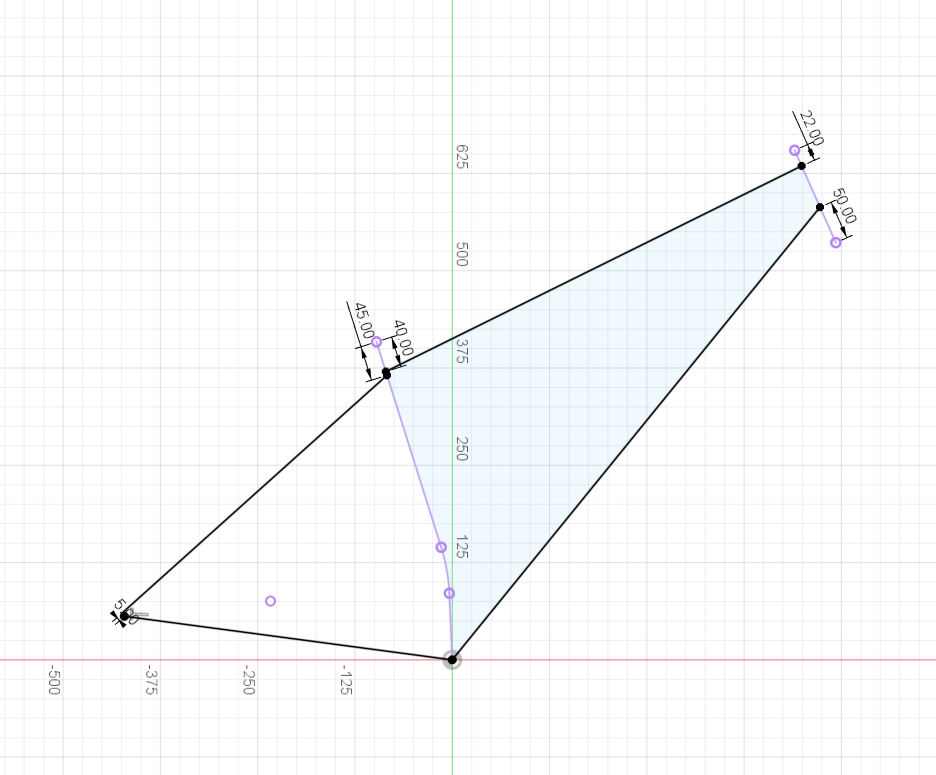
- Create a new sketch, named “ centerlines ”
- Use Project geometry from the base sketch to obtain the following features:
- head tube centerline
- seat tube centerline
- rear dropout point
- draw the centerlines of your front and rear triangles
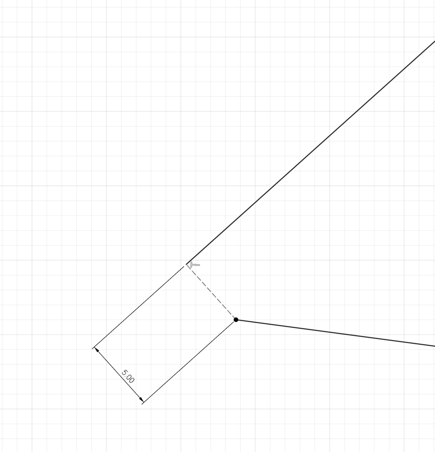
- Dimension the “offsets” as shown
Don’t forget the seat stay offset!
Tips:
- If you did this sketch correctly, all the lines should be black or purple
- Make sure you offset the seat stay as shown above. this prevents the SS from colliding with the CS.
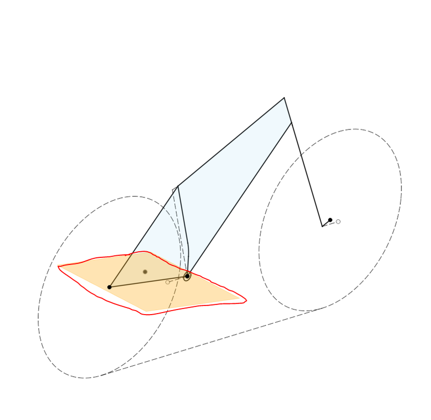
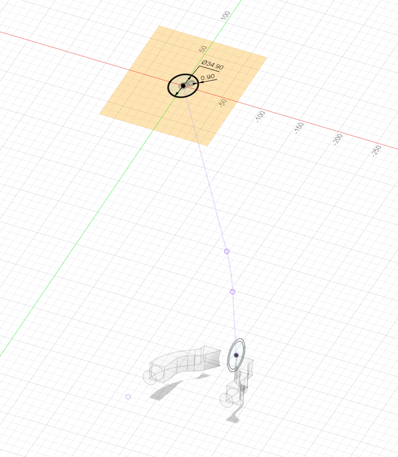
Step 3: Chainstay Centerline
-
Create a reference plane: Construct > Plane at Angle > Click the CS centerline from your centerline sketch
-
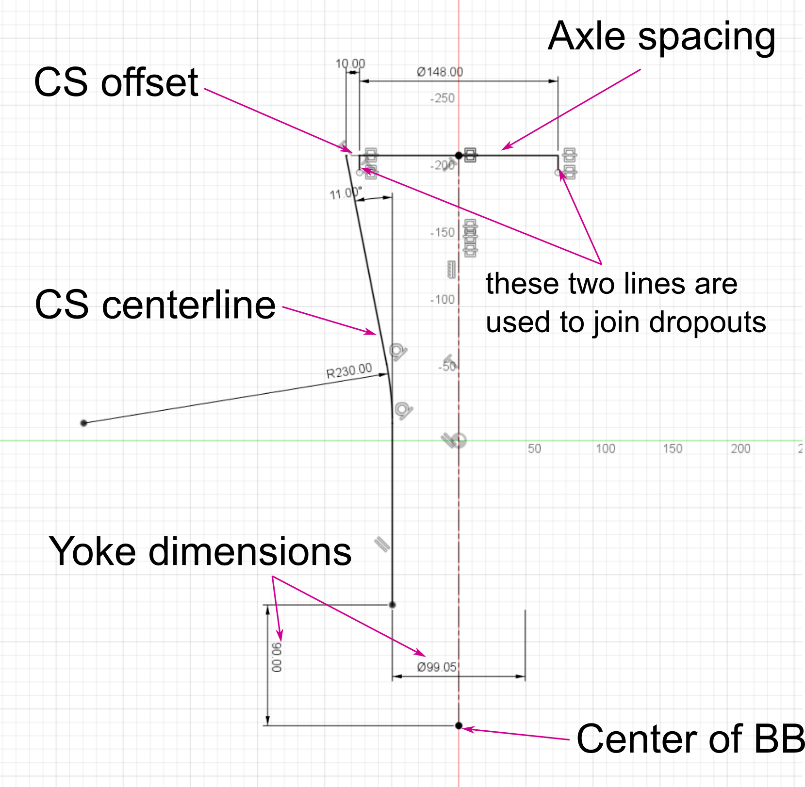
Create a new sketch on the CS plane as shown:
Tips:
- The “Yoke dimensions” come from your yoke’s design. If you are not using a yoke, you will need to draw the CS bends to clear the tire and the chainring
- You will need to toggle the visibility of your base sketches to grab the correct geometries to project
- Don’t forget the two small lines at the axles. Those are used to join the dropouts!
Step 4: Seatstay Centerline
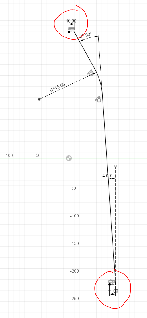
- Create a reference plane: Construct > Plane at Angle > Click the SS centerline from your centerline sketch
- On that SS plane, sketch:
a. sketch the SS centerline
b. make sure you include the offset at the dropout and the seat tube
Tips:
- if you are drawing the seat stays for reals, you need to make sure they will clear the tires!
Step 5: Join the parts
(todo: add CAD model of joined parts, and a video?)
This is probably the hardest step. Fusion360 uses “Joints” which is different from how other CAD packages do it.
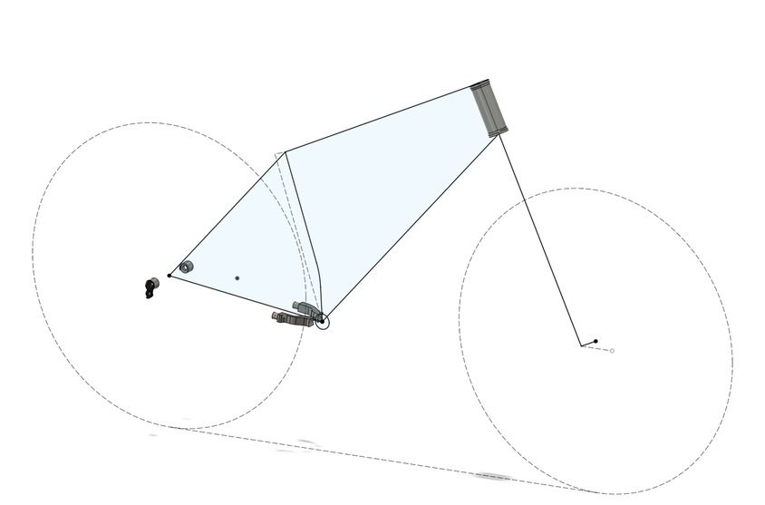
- Join the dropouts, yoke, and headtube to the base sketch
- In the example provided, I drew the headtube from scratch, that way it changes length with the base sketch
Tips:
- Don’t be afraid to delete your part and start over
- Uses the reference sketches to help position your parts
- there are many ways to join the dropouts, this is the best way I have found
- (todo) I provided an example with all the parts and joints
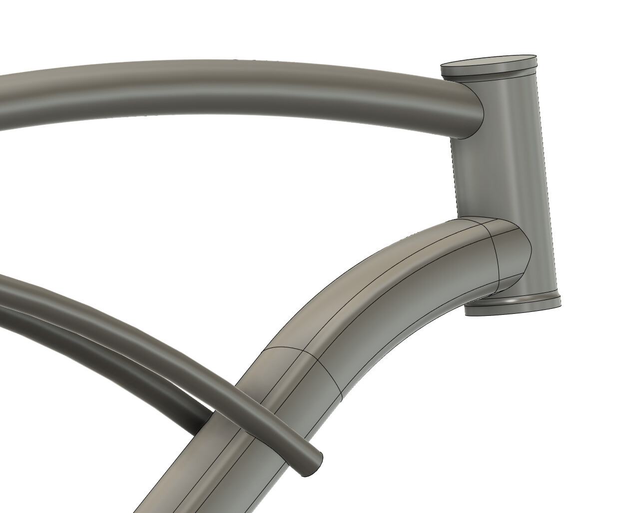
Step 6: Draw the BB and ST assembly
From here, it is all downhill. You are past the hardest part. I like to add new tubes into the assembly as “components”
-
Assemble > New Component > name it “BB ST” > create new sketch
-
Draw the BB shell, and Project the seat tube centerline from your “base sketch”
a. BB is 1.5in diameter, 3mm thick, 73mm wide
-
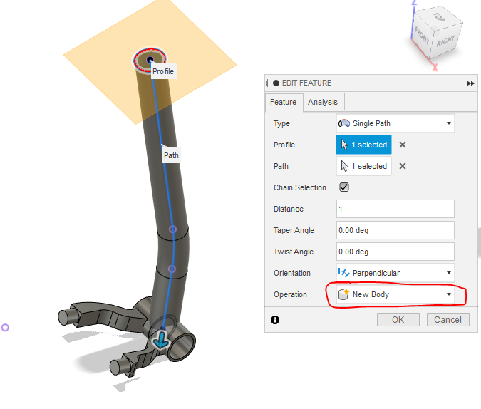
Draw the ST cross-section profile
a. Create the sketch plane: Construct > Plane Along Path
b. Draw the ST cross-section: New Sketch > draw two concentric circles
-
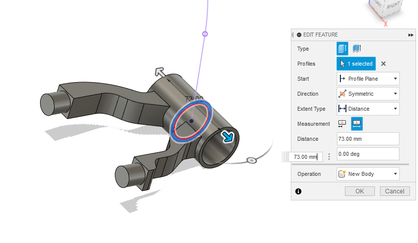
Extrude the bottom bracket shell: Create > Extrude > Click the BB
-
Sweep the seat tube: Create > Sweep > click the ST cross section > click the ST path > choose “New Body”
-
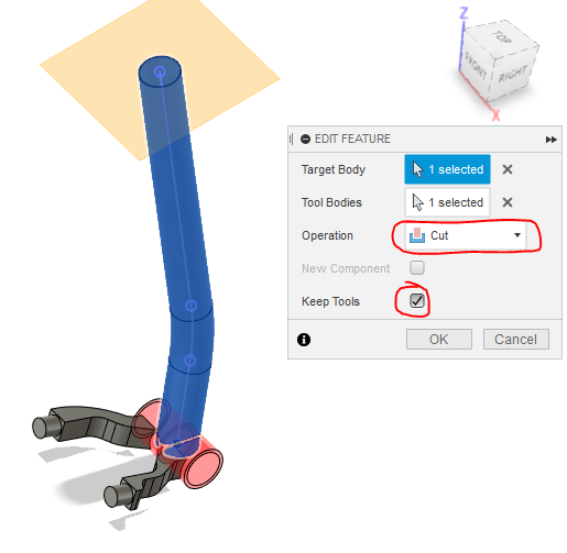
Trim the ST with the BB: Modify > Combine > Target Body: ST > Tool Bodies: BB > Cut > check Keep Tools
-
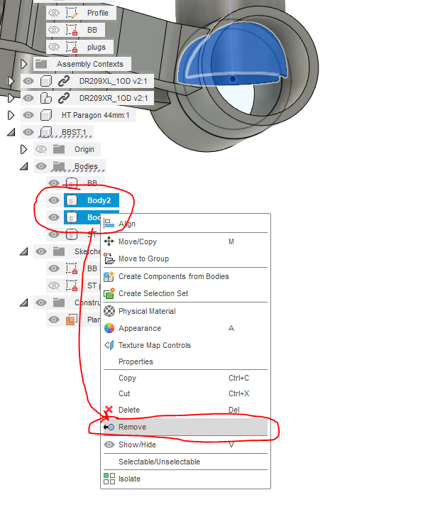
Remove the extra cutoffs: Design tree> right click the cutoff bodies > remove
Step 7: Draw the rest of the tubes
The remaining tubes: TT, DT, SS, CS follow the same workflow
- Create a sketch plane using “Plane Along Path”
- Sketch the tube’s cross-section
- Sweep the cross-section along the path
- make sure you create “New Body”
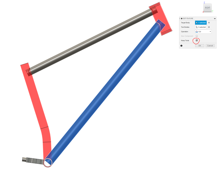
- Trim the miters using “Combine”
- make sure you “keep tools”
- Remove cutoff bodies with “Remove”
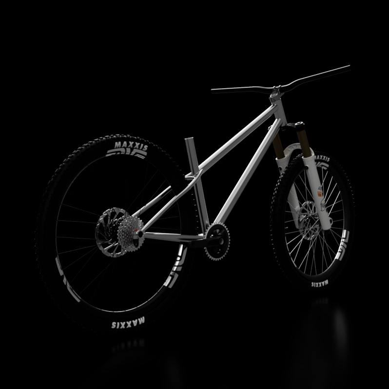
Step 8: Cleaning Up
- Add a Brake tab
- Add brake brace (SS to CS)
- Add SS bridge
The rest is up to you! The next big tutorial will be how to translate your 3D drawing into 2D construction plans for your bike! (todo: make this tutorial)