I created this thread to discuss the Shutup and Build Bikes podcast, hosted by Joe at cobraframebuilding.com
My Background:
- Mechanical Engineer
- Frame designer, engineer, and 3D printing guy
- Grad school for Robotics and Control:
– Design, dynamics, control, simulation, etc…
– built some cool robots:

What I am doing now:
- Worked in tech at a 3D printing company for 2 years as a software engineer
- Recently got laid off (November 2022)
- Decided to pursue framebuilding technologies for the next 8mo
- Writing my dissertation
- Working with Nick at Neuhaus Metalworks
- Design, consulting, and project management with Peter Olivetti at Merlin
- SUPERB Components: low-cost components designed for small framebuilders
- Offer better value on complete bikes
- Make custom frames more accessible
- Higher (relative) margins
- Developing this forum
Digital Design Process:
I use Fusion360 to design our (NMW) bikes. It’s faster, more accurate, and enables more complex solutions. I developed a digital workflow that automates a lot of the design process. It takes me about 2 hours to design a new “model” (for example a dirt jumper) and create the construction drawings. But once the initial model is done, I can create custom DJ designs and 2D construction drawings in minutes.
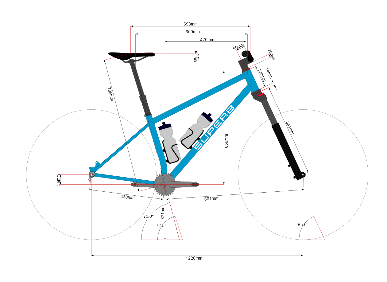
Step 1: Fit and geometry scratch work in BikeCAD
BikeCAD is great for doing quick scratch work. You can iterate very quickly, and the cockpit and seating dimensions are very useful to fit customers
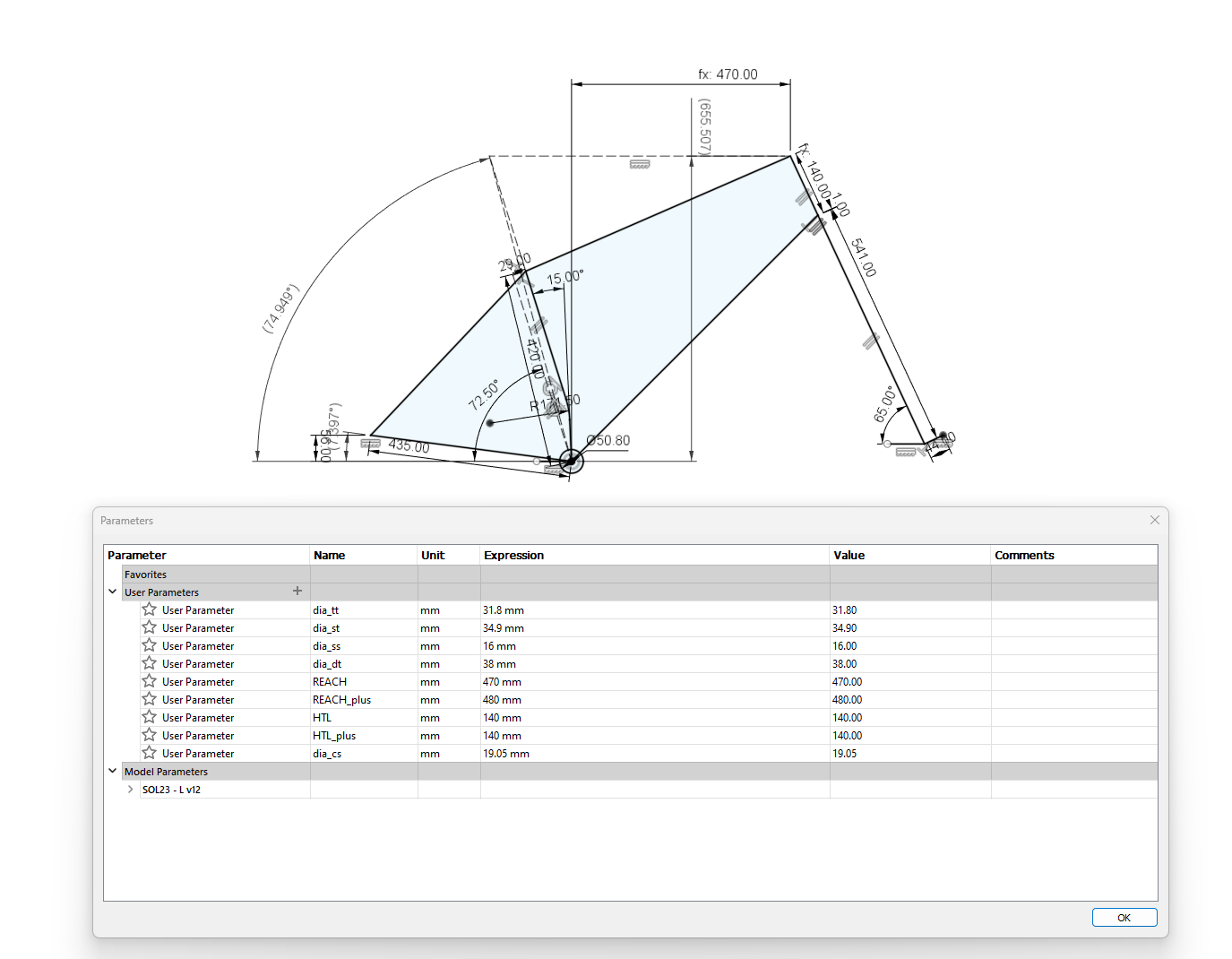
Step 2: Update Fusion360 Parameter table
Update a 2D base sketch and parameters:
- geometry information: (reach, HTA, CSL, HTL, fork A2C, etc…)
- Input tubing diameters: (TT, DT, SS, ST, CS)
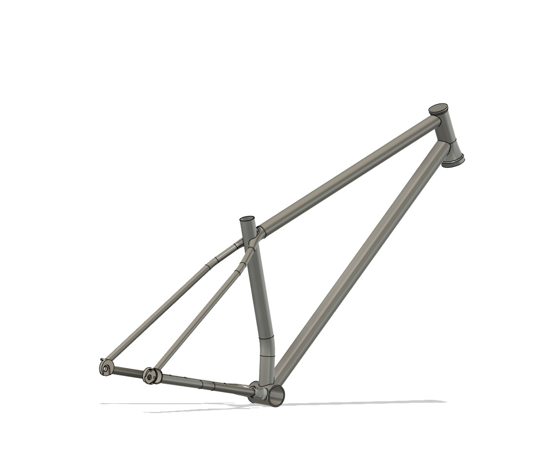
Step 3: Automatically Generate 3D CAD
The 3D CAD automatically generates from the parameter table:
- Tire and drivetrain clearances are baked into the model
- Downtube location is directly driven by fork crown clearance
- HT, bb, and dropouts all automatically scale/change
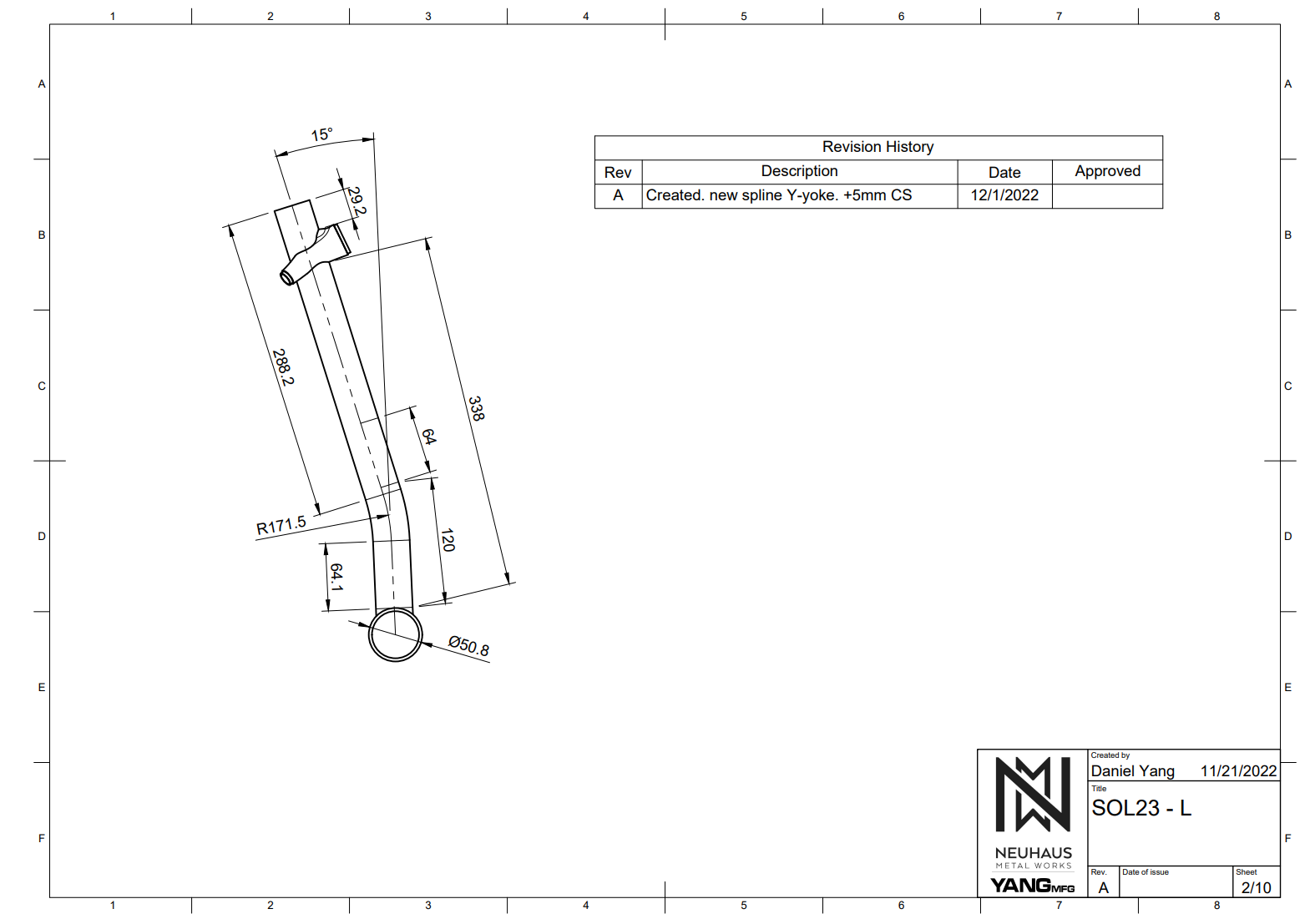
- 3D printed y-yoke automatically generates
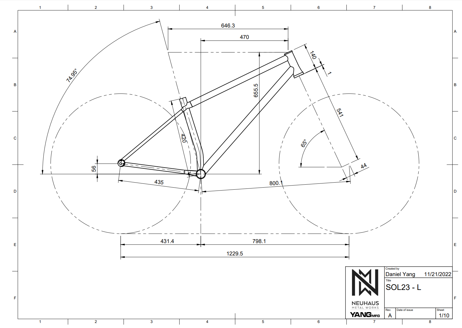
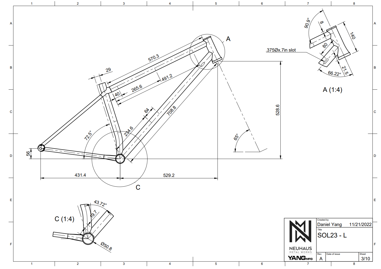
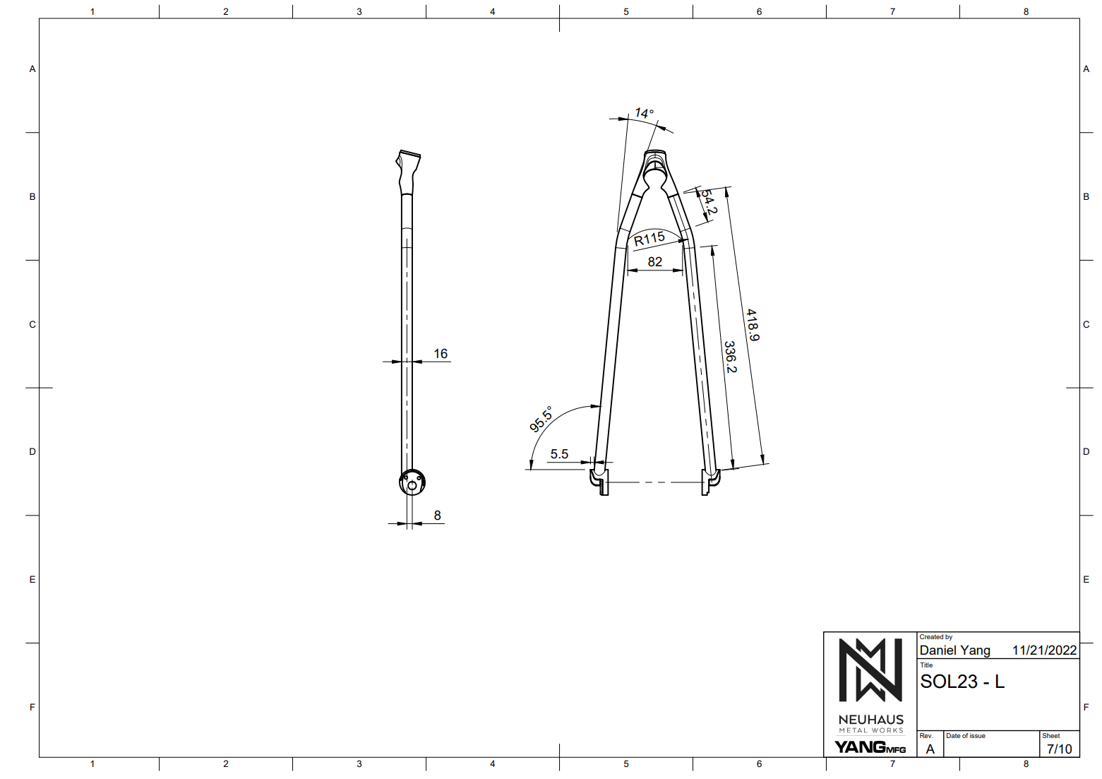
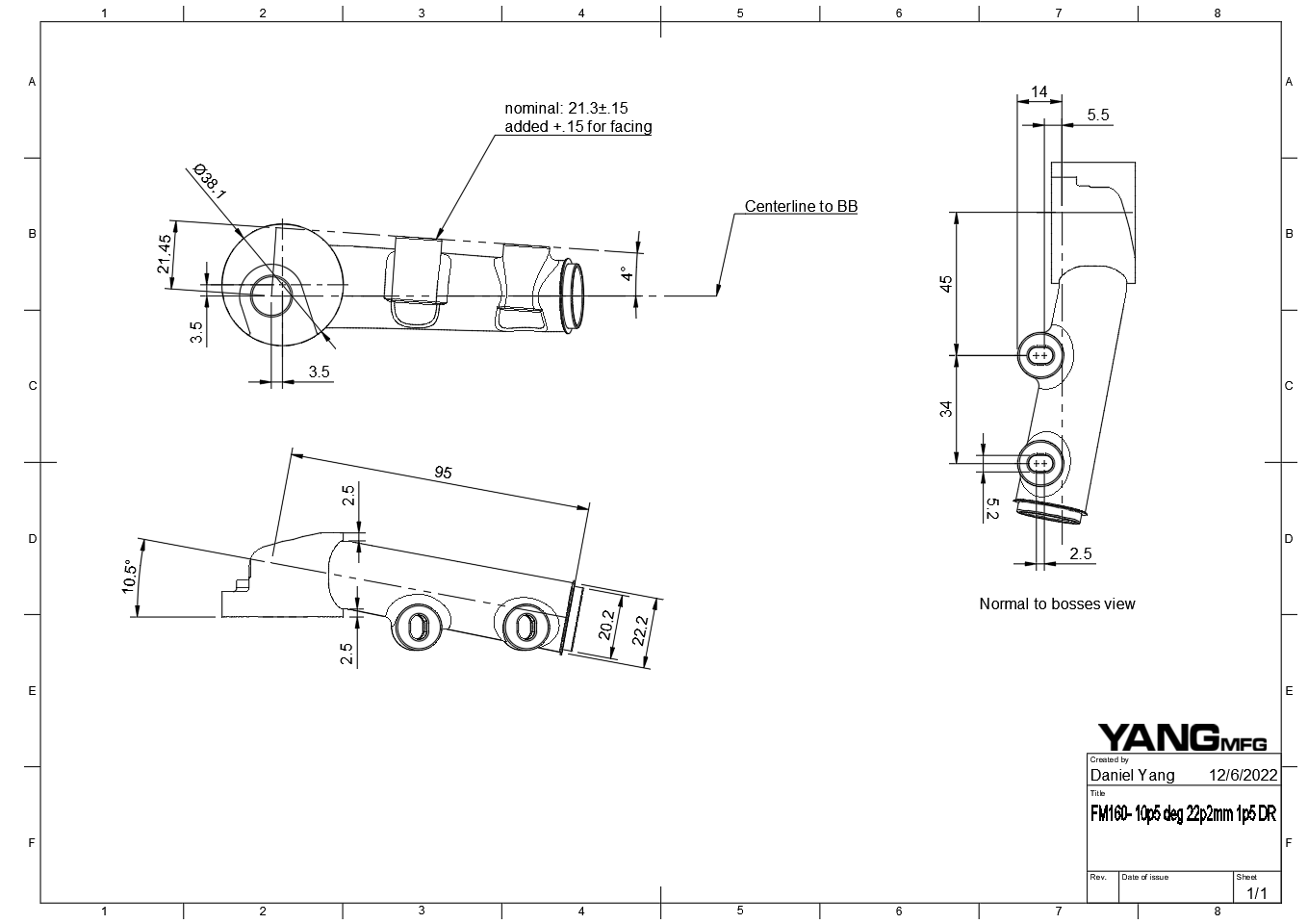
Step 4: Automatically Generate Construction Plans
A full set of 2D construction drawings is linked to the 3D cad. If you update the 3D file, the 2D construction drawings automatically update. I think this is the most powerful step of the process. These drawings are very accurate (I would guess +/-.2mm) and take the guesswork out of construction. It also breaks down the manufacturing process into steps so it is easier to read.
Step 5: 3D Printed Parts
The printed parts are not necessary for the digital design process. I use Fusion to create traditionally manufactured bike designs or other builders. However, the printed parts make life a lot easier.

Every part we use must:
- be a time savings
- be a cost savings
- solve a problem
3D Printed Designs:
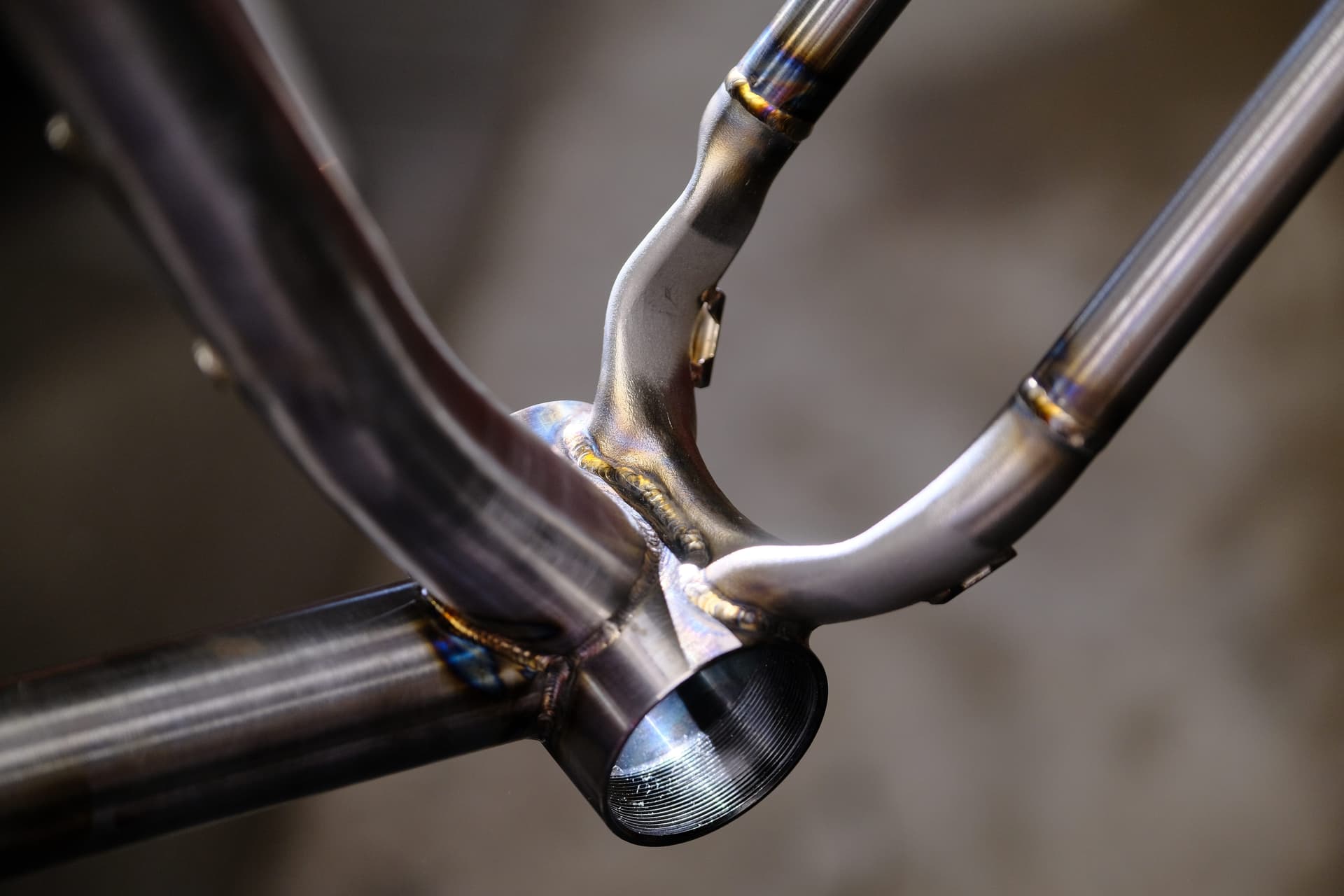
Y-Yoke:
- pretty big time savings
- it gives you a precise alignment point that couples the front and rear of the bike
- creates a stiff bulkhead where the SS, ST, and TT join
- looks cool
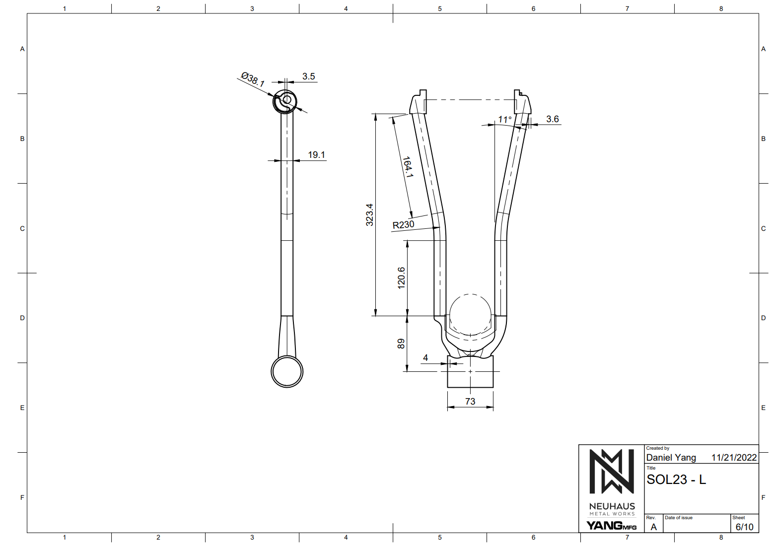
CS Yoke:
- CS yoke is very cost-effective compared to traditional manufacturing
- Saves time by taking care of all your tire clearance and drivetrain questions
- Design Specs:
– T47x73mm
– 29x2.6in with 6mm buffer
– 34t chainring with 52mm (boost) chainline
– Weight: 120g
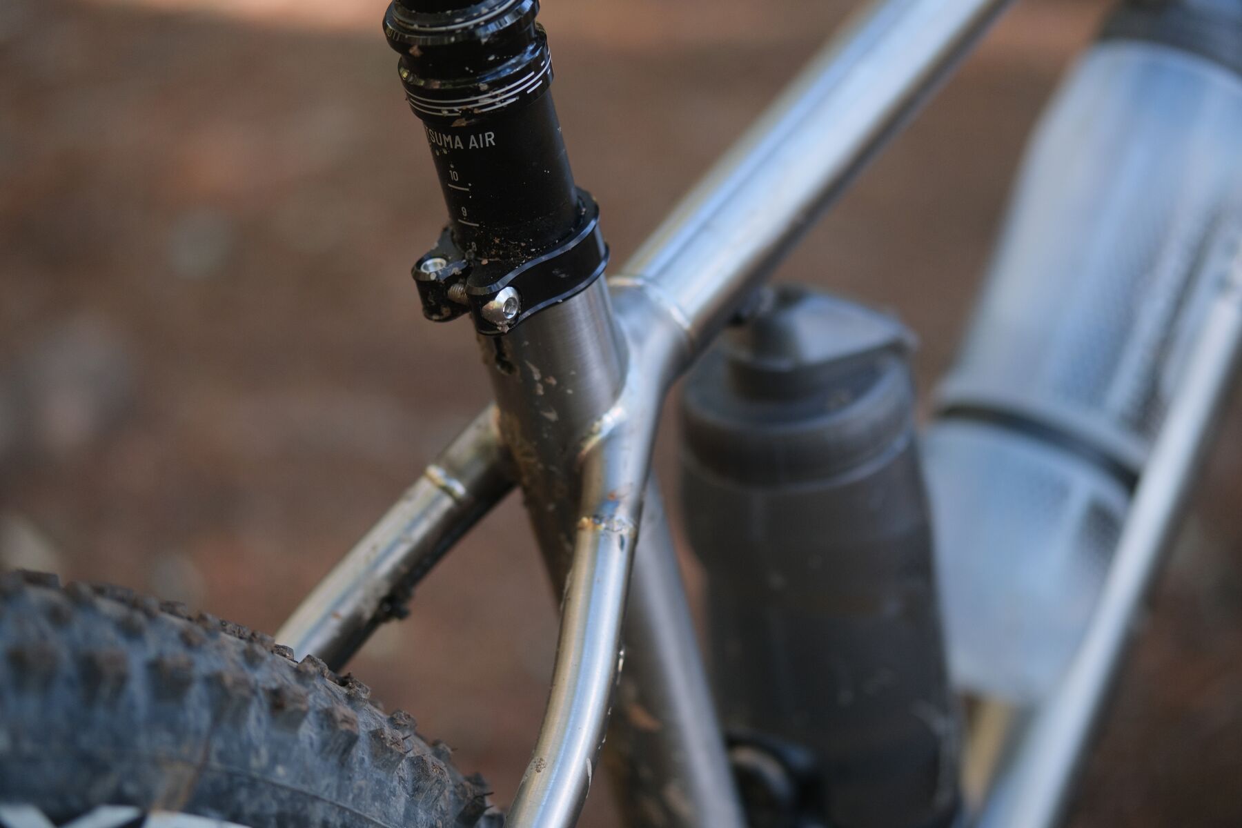
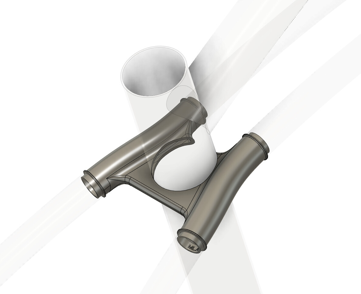
Bottle Bracket
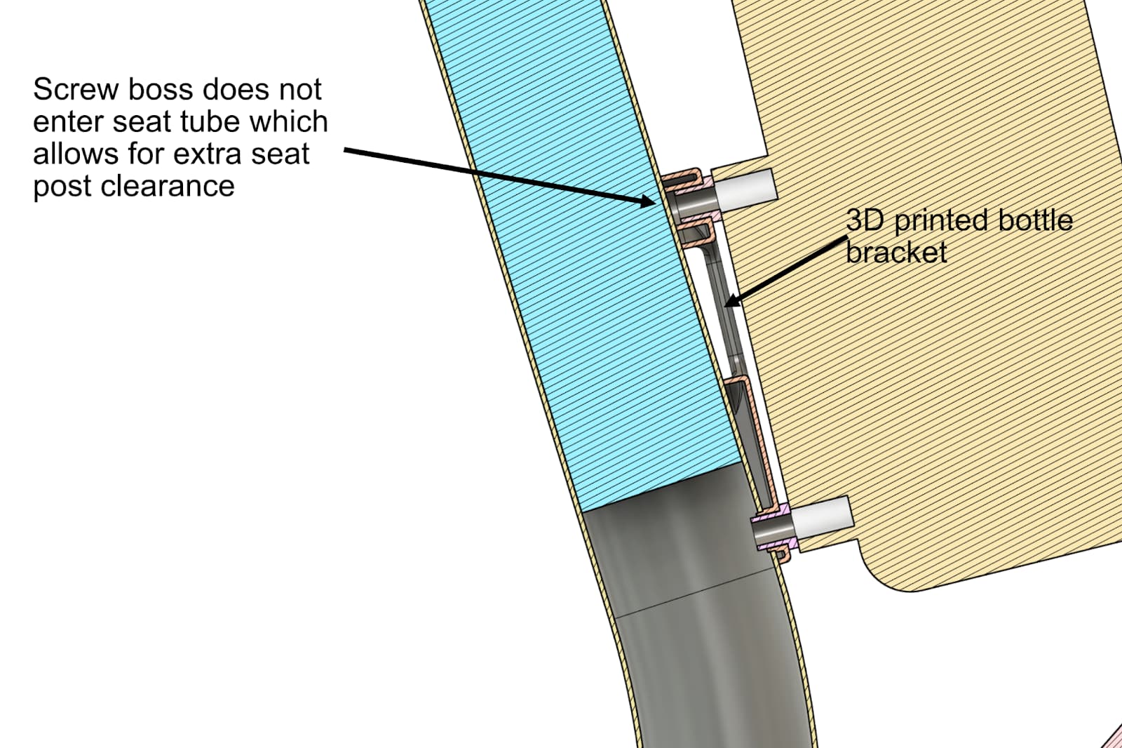
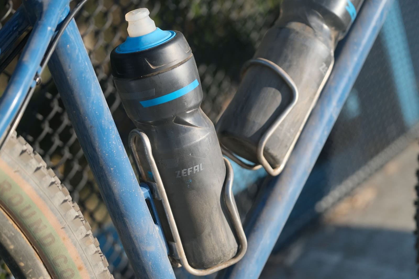
- Allows you to use regular bottle bosses on the ST with a dropper
- angles the bosses ~5deg to keep the top bolt out of the seattube
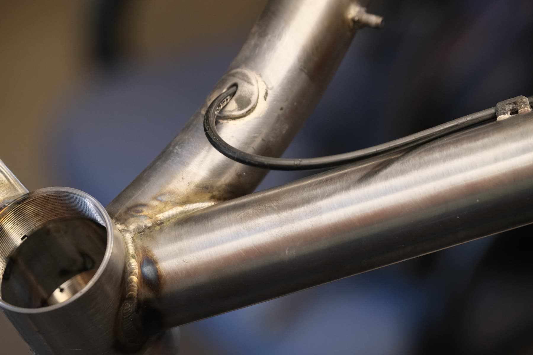
Ports:
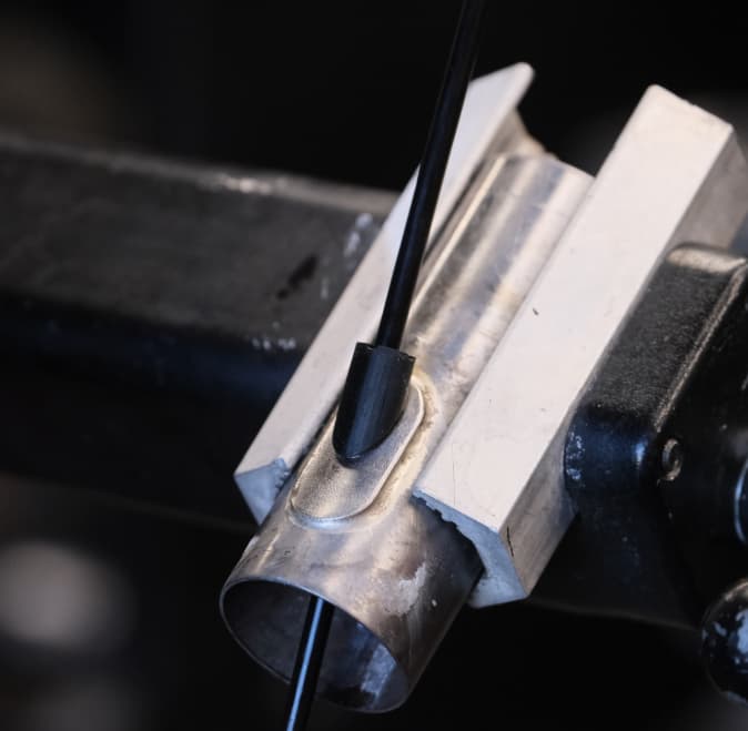
- Cheap and effective
- Time savings
- Slot and braze. No filing and test fitting
- 3D printed urethane port
- weather sealed
- keeps the cable tensioned to avoid rattling
- drywall style anchor to keep the port in place
3D printing discussion:
What printing is good at:
- thin, lightweight structures
- impossible designs
- low volume production (<100)
- lower barrier to entry
- customization comes for free
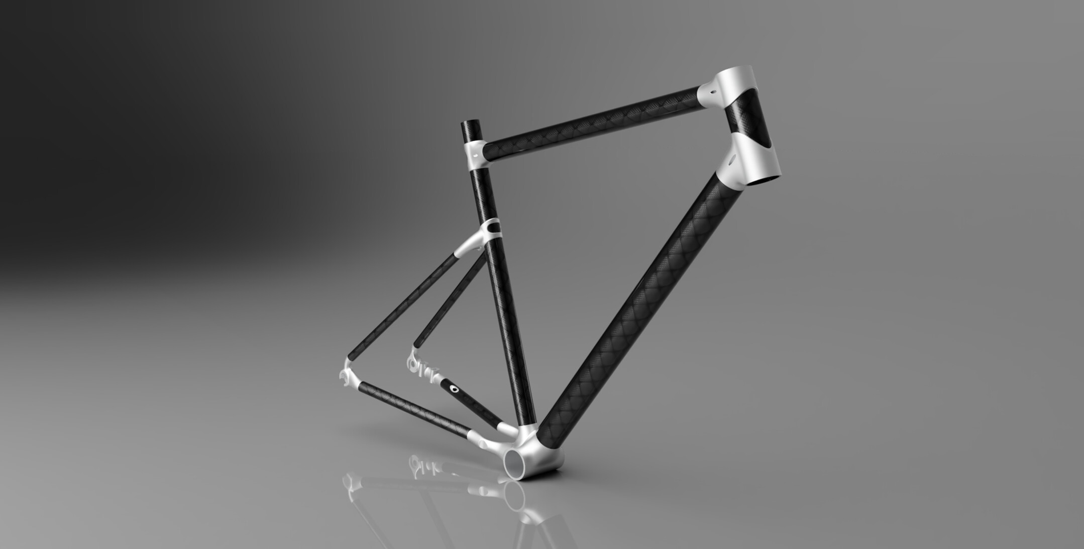
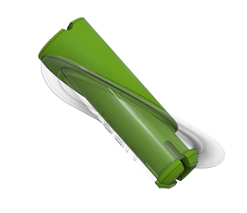
This yoke for a twin top tube design part would be nearly impossible to machine.
The FM160 adapter is a very complex, thin, lightweight structure, making it a good candidate for 3D printing.
Why 3D printing will always suck:
- Labor Intensive
- Parts larger than a (really small) shoebox will be really expensive
- Varying Mechanical properties
- affected by: design, “defects”, print orientation, printer make and model, machine settings
- Accuracy
- if you CT scan your part, its always off from your model
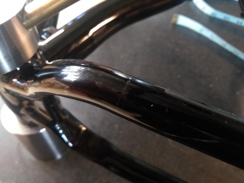
- parts are always warped
- different accuracy/scaling between horizontal and vertical directions
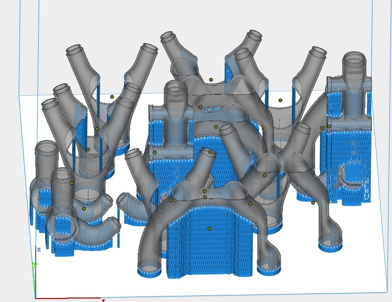
All this material has to be removed by hand!
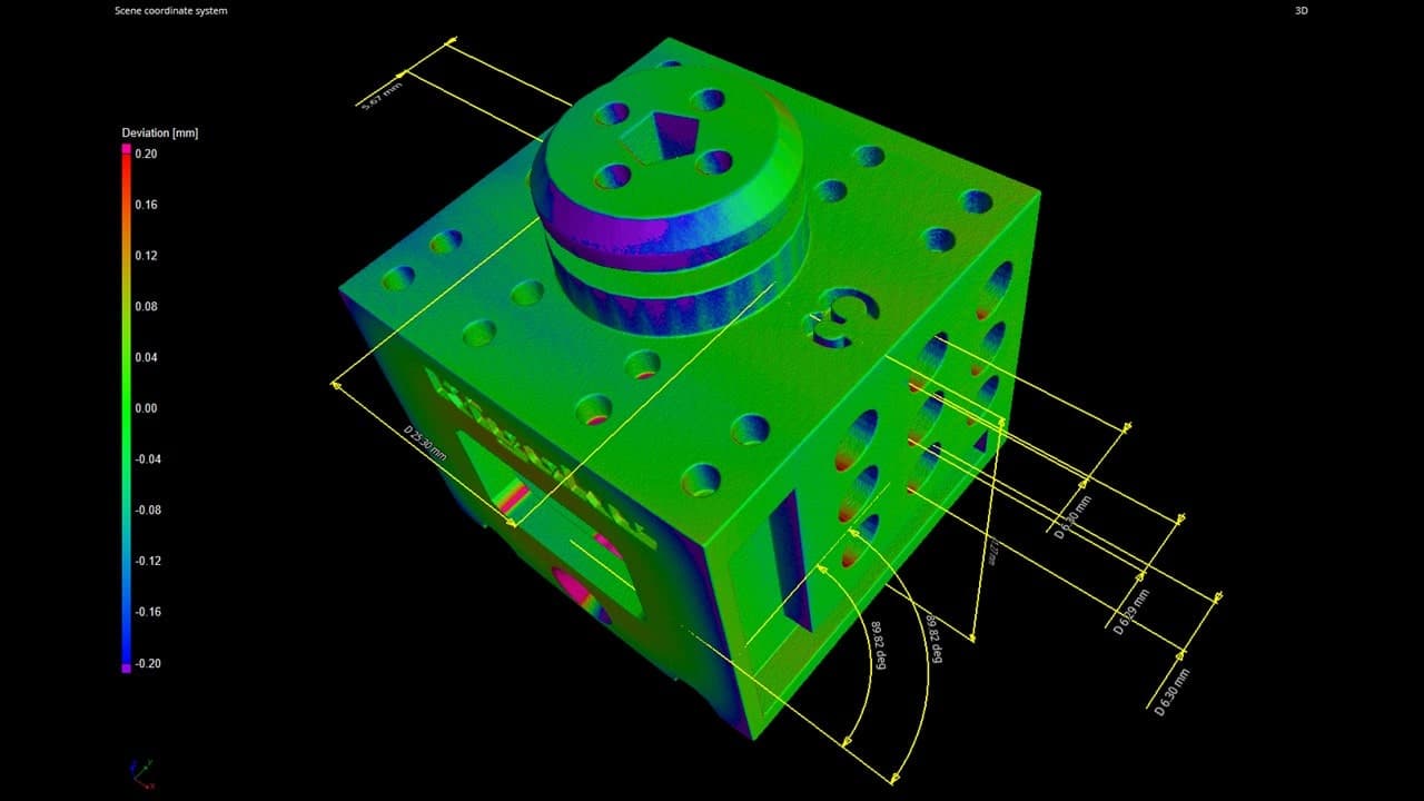
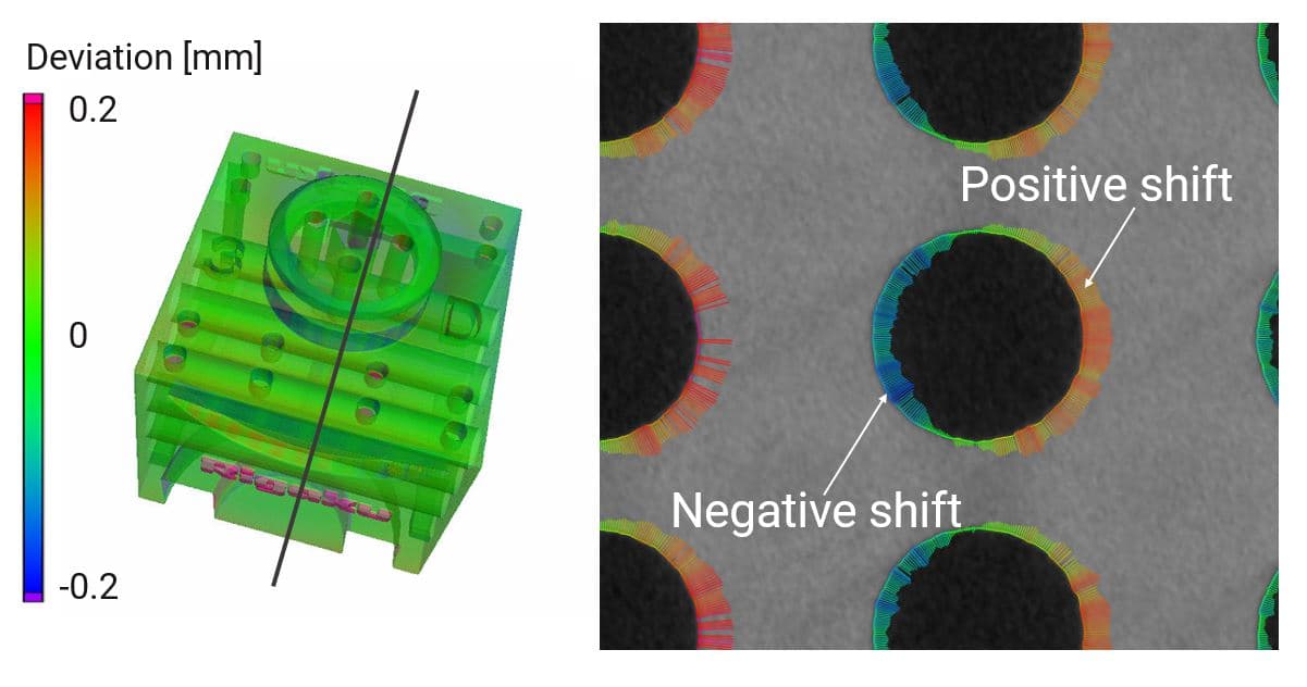
3D printed parts are always warped in the worst ways. Diagrams respectfully borrowed from (https://imaging.rigaku.com/industries/metrology/3d-printed-plastic-dimensional-analysis-by-x-ray-ct)
How to get Started in Metal 3D printing:
- Learn 3D CAD: Fusion360
- Ask questions and share projects on this forum (shameless plug)
- Get the design guide from your print partner:
- minimum wall thickness/feature size?
- minimum unsupported bridge?
- Max overhang angle?
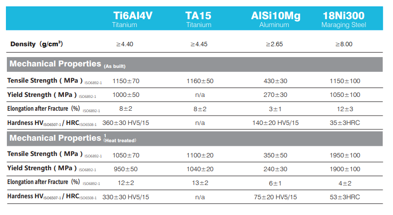
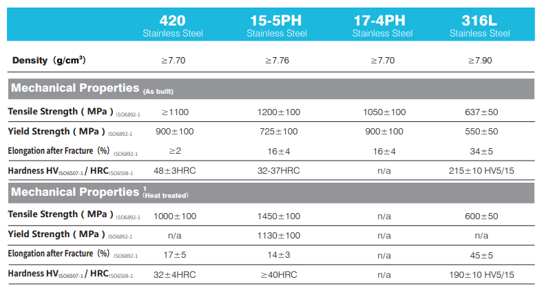
- Mechanical properties?
- Understand the limitations
- parts will be warped
- parts are not as strong as bulk materials
- 3D printing is both fast and slow:
- 1 month lead time
- Every mistake sets you back 2-3mo to go through the design and print cycle
- Costs (316 Stainless):
- $.5-.8/g
- $100-200 for heat treat
- ~$100 Shipping
Things you should do:
- Gradually phase in 3D printing into your process
- start small: ports, braze on, chainstay yokes
- Print test parts to find the limitations of your printing process
- don’t just believe your printing partner!
- don’t just believe other builders! (including mine)
- Print labels on your parts (I have a bucket of mystery parts before I realized this)
- Do the 2D drawings BEFORE you print
- catch mistakes before you print
- 2D drawings will remind you what you designed when the parts show up a month later
- Think like the printer, be the printer.
- Design simple, smooth shapes
- avoid thick to thin transitions
- avoid sharp interior corners (aim for >.5mm radius)
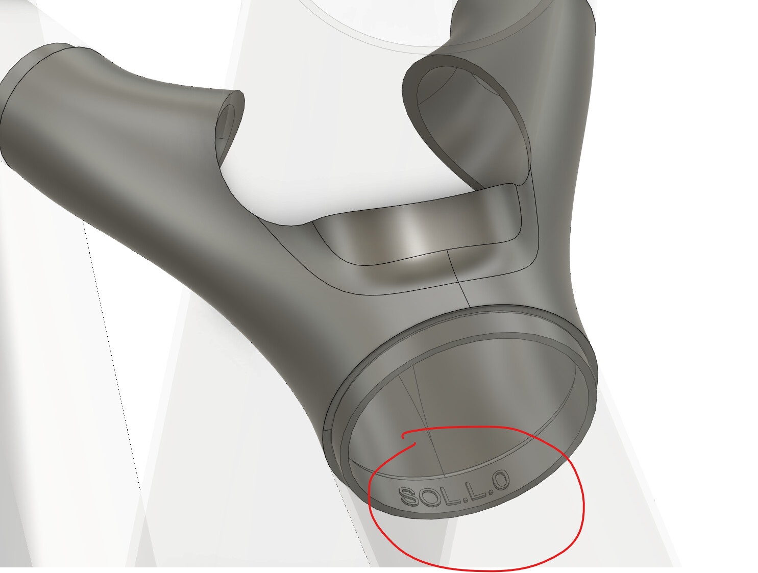
Parts are labeled: SOL.L.0 (model.size.version). Do 2D drawings to double-check check your part is correct.
Traps to avoid:
- Don’t print fancy things for the sake of printing things. Simple is better
- Don’t rely on support material. A good design is self-supporting and does not require post-machining
- DO NOT make cost-driven decisions!
- reducing weight is NOT to make the part cheaper
- DO NOT optimize weight or take on risky prints unless you have a test plan in place!
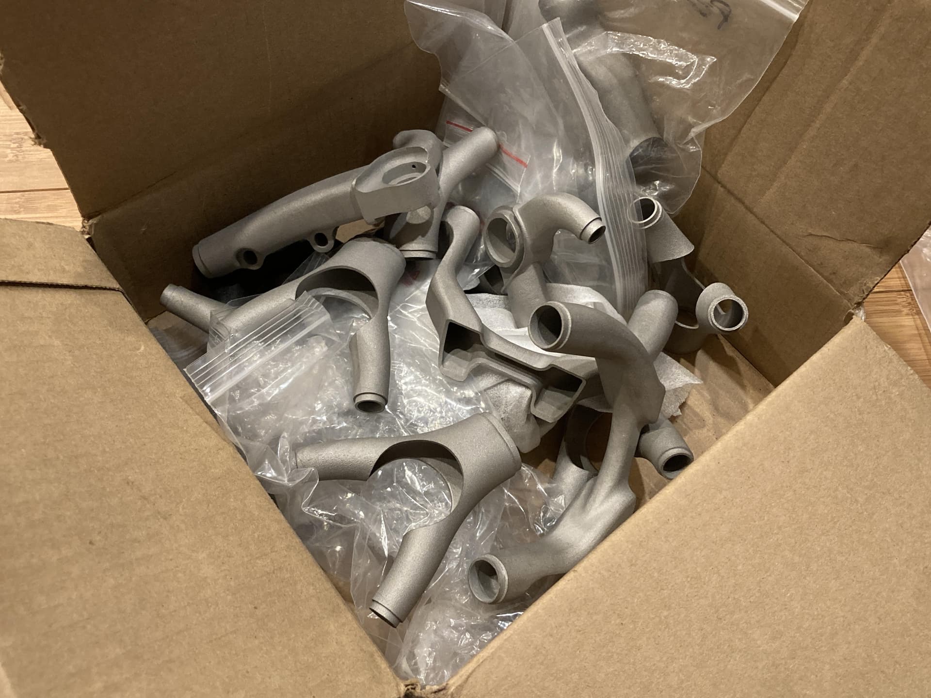
Bucket of mystery parts without a home. I have no idea what bike they belong to, and how to use them anymore. This is a good lesson to label your parts and do your 2D drawings!