When it rains video tutorials, it pours. But really though, its been raining on and off the past month, and I am getting stir-crazy.
Forward:
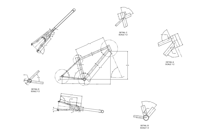
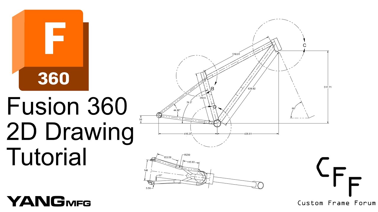
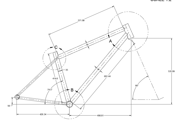
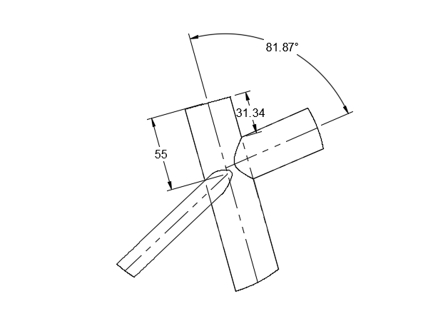
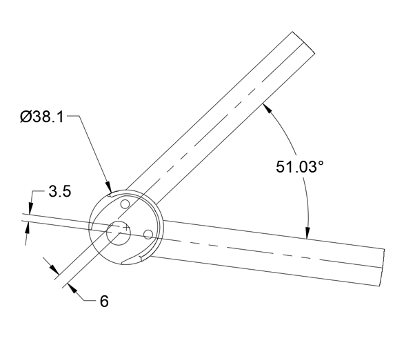
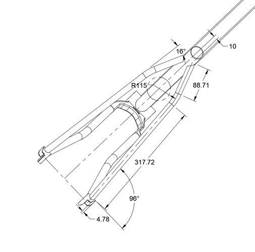
In this tutorial, I show how to create useful 2D drawings that can be used to construct a bike in real life. If you take the time to understand this tutorial, you will have a very powerful tool in your toolbox. Fusion360 2D drawings are more accurate, customizable, and automatically generated.
It has taken me over 500hrs in CAD to develop this workflow. I considered keeping it to myself to keep my competitive advantage, but I believe the information is better off living in the community. I hope that this tutorial can help modernize framebuilding: make it more accessible to hobbyists and more efficient for professionals.
one quick note: I use the paid version of Fusion360, which allows me to split up drawings into different pages. For this tutorial, I placed everything on a large sheet to work around the “one sheet” limit. However, I have not tested my tutorial with the free version, so please let me know if there are issues!
Video (Make sure you watch in HD!):
Files:
Download through autodesk website (recommended):
- Fusion 360 link: Finished Model
- download > fusion360 Archive > enter in email
- downloading the drawing archive will download the 3D frame!
PDF: MTB Demo Finished Drawing v6.pdf (146.8 KB)
Fusion File: MTB+Demo+Finished+Drawing.f3z (1.4 MB)
Step 1 - Reference Sketch 03:15
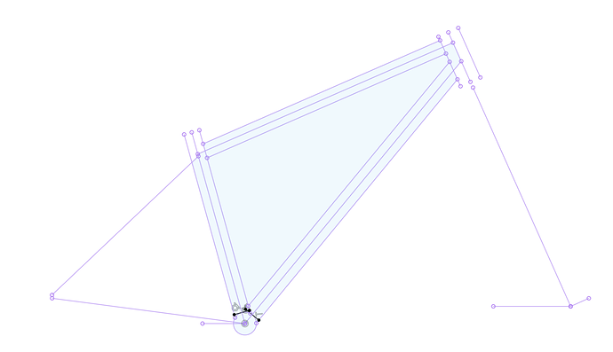
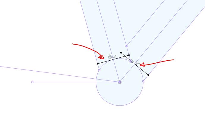
The reference sketch is drawn in your 3D assembly and is used to create pull dimensions in your 2D drawings.
Don’t forget these two BB tangent reference lines!
Step 2 - Create 2D Drawing 06:32
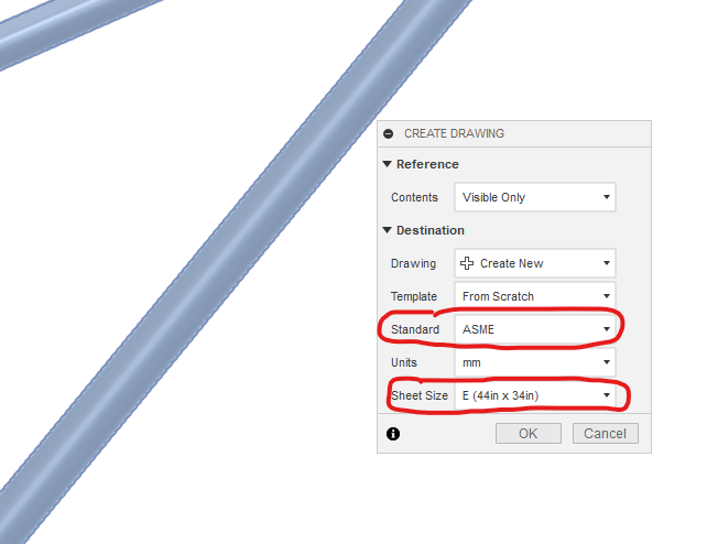
File > new drawing > from design
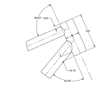
Headtube Details:
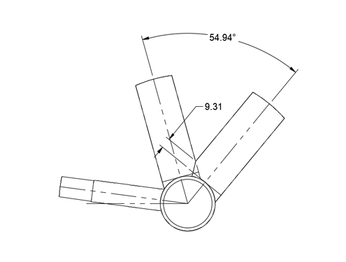
BB Details:
ST Details:
Comments:
I forgot to show the dimensions of the dropout. This is useful for the SS and CS offsets due to the 1.5in diameter droupouts:
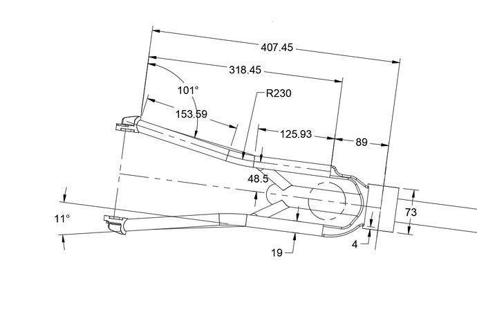
Step 3 - Create SS Auxilary View 12:37
Comments:
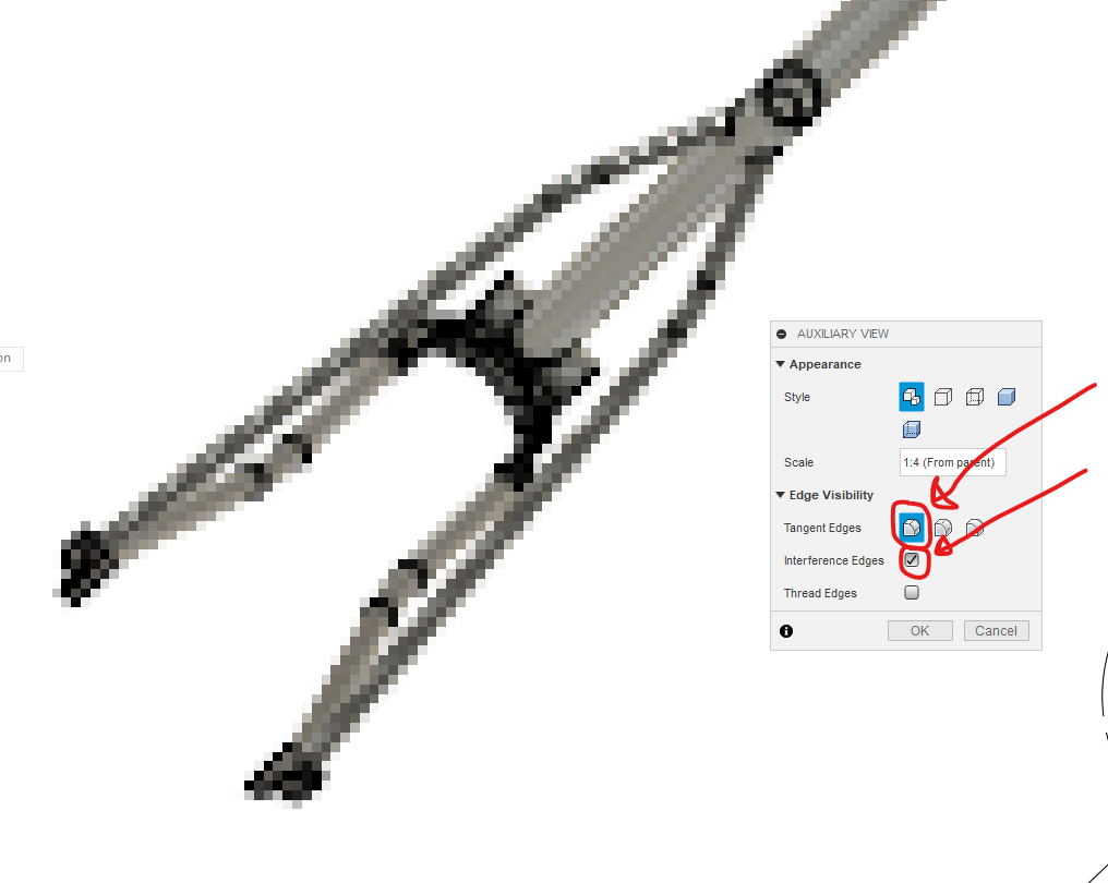
- Make sure you check the “Tangent Edges” and “Interference Edges” boxes!
Step 4 - Create CS Auxilary View 15:05
Comments:
- Make sure you check the “Tangent Edges” and “Interference Edges” boxes!
- Everyone fixtures their chainstays slightly differently, so pull the dimensions you need
Conclusions 17:44
There will inevitably be missing dimensions or specific dimensions you need for your workflow. You may need to create more reference sketches in your 3D CAD or modify your CS and SS centerline sketches.
Hope you enjoyed the tutorial. Let me know if you have any questions or comments. To show thanks, please post up your results!
