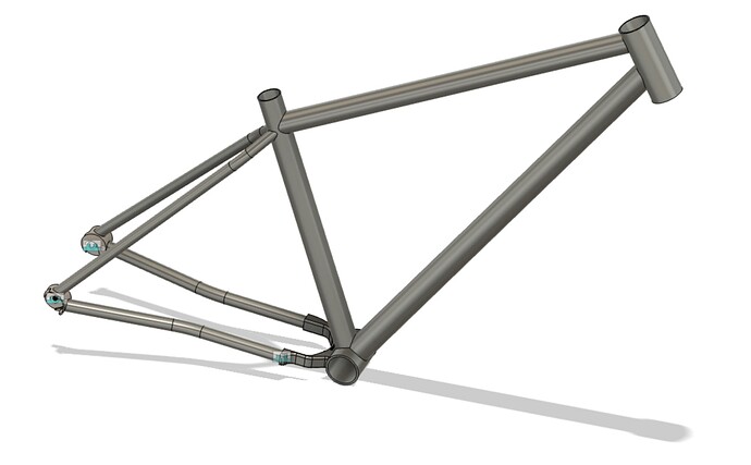
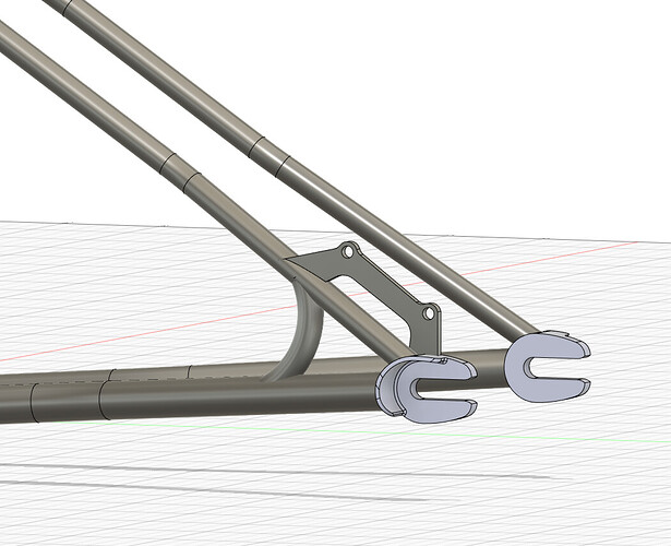
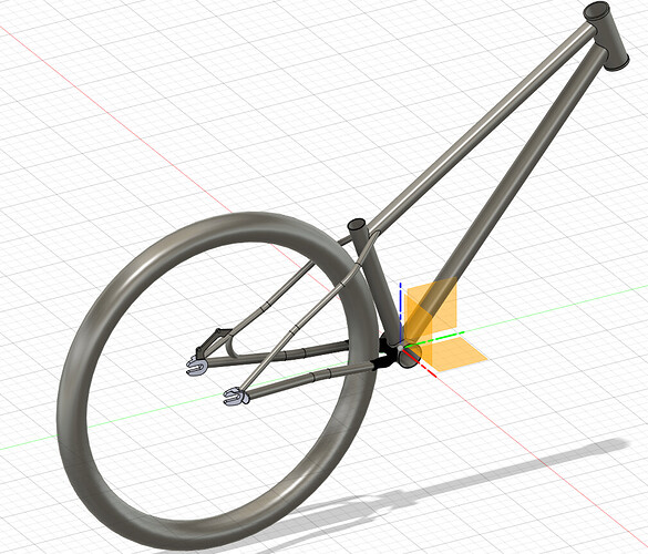
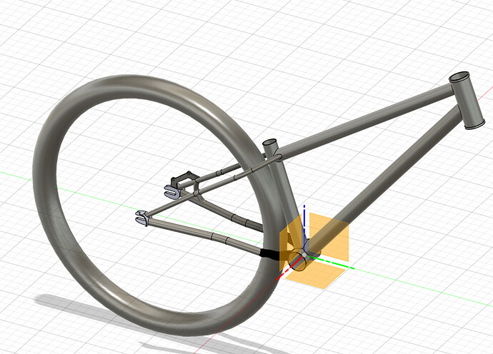
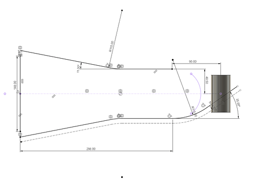
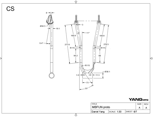
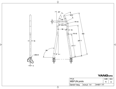
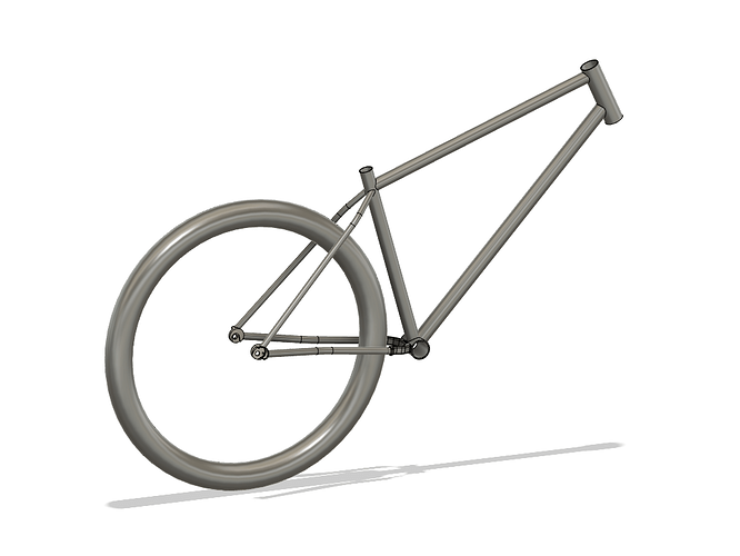
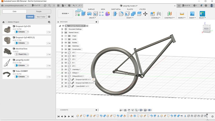
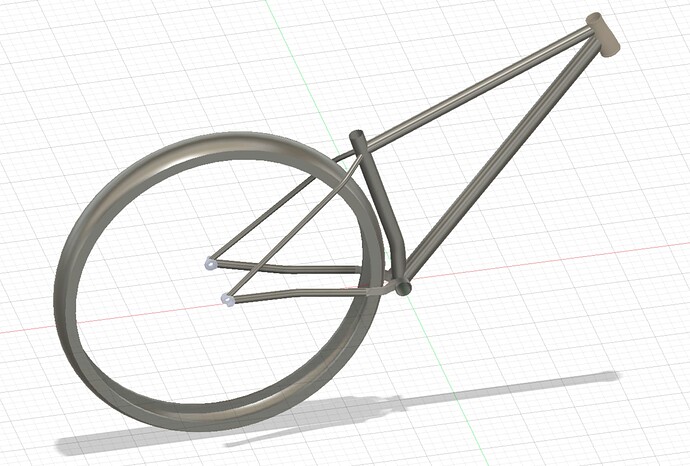
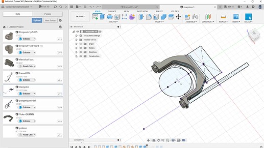
Got it all done!
I can’t vote for all of the above!
MTB yoke
gravel yoke
Fat bike yoke
Bring PMW step file into F360
Great resource! Thank you.
A few tweaks for me to try. I’ve not removed the extra bodies before- only hid them.
I use the same sketch template but have separately modeled every Columbus tube and just import them as required and can move them around based on where I want the butting.
Do you know of any way (other than creating the tubes with a seam and converting to sheet metal) to ‘unwrap’ a tube in Fusion to create a mitre template? Can be super useful for tricky builds like the Columbus Cento tubeset with the funny BB.
That is a good idea! I typically avoid the butting (or even holloing the tubes!) to keep the CAD more robust. But I can see it being useful in other people’s workflows. Especially pre-bent stays. Maybe we can start a library of tubes…
I didn’t explain it in the video (because it would take too long). Both methods have their flaws:
- If you hide the extra bodies, when you create a 2D drawing view, Fusion decides to unhide ALL of your bodies…
- If you remove the extra bodies, your CAD will break if one of those bodies “dissapears”. Fusion will look for the next avalaible body, which is is the main tube that you want to keep, and remove that one instead.
Both methods are flawed, the important thing is being able to fix it!
Unfortunately, I think that is the only way… You could skip the middle man (2D printer) and just go straight to a 3D printed template ![]() .
.
Hi @Daniel_Y,
Thanks for the great video and for sharing your workflow!
I’m happy to see that my process is almost identical. ![]()
I’m curious to know why you prefer to create a “plane along path”, and then draw a sketch with the tube diameter instead of just using the pipe command?
I’m usually just using the pipe commands for TT, DT and ST and then using the combine cut/combine join for the assembly… maybe my flow is not correct?
I think the idea about a tube library that you and @Ian are talking about sounds great! Dropouts, bosses and other parts could also be included. I would be happy to contribute.
If anyone in this forum is skilled with Fusion360 simulation/FEA, then I would love a bike frame stress test simulation tutorial. Would be nice if it could be conducted according to ISO4210
Best,
Frederik Sølver
Thanks, @Frederiksoelver!
According to others on this forum, pipes work fine! One reason why I use construction planes is that the tutorial is designed for beginners. I wanted to show fundamentals, not shortcuts.
The second reason is more of a philosophical point. When I create a CAD design, I am not just trying to get something to look like a frame, I am trying to create a robust and versatile parameterized model that can be used to build a frame IRL. The pipe command saves 10 clicks and 1min/tube but it locks you into using round, hollow tubes.
Once I complete a set of 3D and 2D drawings, I will branch that set of drawings into different sizes and geometry. To me, saving 5min of CAD in the initial model is not worth the tradeoff in flexibility down the line.
Point taken.
I guess sweep is great when working with oval and other shaped tubes.
I usually use pipe combined with parametric design tables for round tubes, but I also get why you choose to show the other option.
I’m glad to have found this forum!
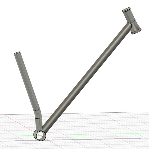
Messing around some more to reinforce what I learned on the last frame. This time I drew the BFS tapered headtube and created a parameter table to adjust geometry. I also generated a sketch for DT to Fork crown clearance so that as the geometry changes the clearance is maintained.
Good tips to know.
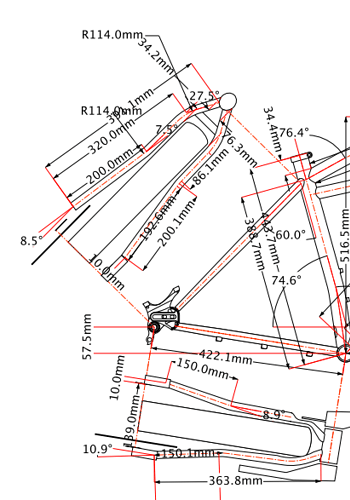
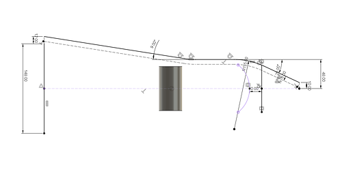
I am happy to start a tube library (where can we host it?). As much as you don’t want to, I’d love to see how you draw up factory bent/tapered stays. I do away with the butting when I do it and just draw the bend and taper according to the factory specs, Its never going to be 100% with what you have in your hand as the CAD model won’t thin out at the bends as it does in the real world but that’s only a good thing as in the 3d model you’re working more with a worst case scenario of clearance to tire/chainring.
Thanks for volunteering! let me think about the best way of hosting these files. For now, you could throw it into this new CAD library thread. It would be really cool to have 2D drawings for the parts as well. A lot of drawings are incomplete, inaccurate, or don’t even exist. I’ve bought so many stays just to measure them, only to find they don’t fit my application! I’m sure that happens to others as well.
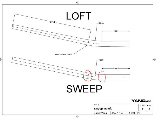
When I CAD tapered stuff, it’s just a loft instead of a sweep. However, I rarely CAD tapered tubes because the loft tool will not show bend locations on the 2D CAD: see below
My 3D workflow is “production CAD” and revolves around creating robust and accurate 2D CAD quickly. I omit tapered seat stays to make the drawings more clear. However, with custom frame building, I could see the tapered stays, tube butts, etc… would be very useful. Just drag, drop, and join it to a centerline sketch!
This might be very odd but I don’t make 2D drawings of the frames I CAD (not since switching from Solidworks to Fusion), just of parts I want to get machined… This will be why I haven’t run into the loft vs sweep issue on the 2D drawing!
There is going to be a margin of error on every bent stay. Myself and other local builders have had the same model stay be a few degrees out across several samples. More so on Dedacciai tubing than any other but it happens on all of them.
I think its really funny: Fusion is from autodesk, which was the king of 2D CAD. But for some reason, Fusion 2D drawings suck compared to Solidworks!
I know most people just look at their fusion sketches to build their bikes. I know it works, but I think there are a few reasons to go through the exercise of creating 2D drawings:
- Create drawings for your workflow: How you create a sketch in the 3D file is rarely going to be the same dimension you need to fabricate the bike. Creating construction drawings allow you to call out the exact dimension you need in your process.
- Catch design mistakes: When I started using the 3D workflow, we (NMW) made a few costly mistakes. Since then I made a rule: we don’t order parts until I completed the 2D drawings. Since then we haven’t had any big oopsie. The drawings offer a second pass over the design and give you a quick sanity check before you invest 10-20hrs on building the frame.
- Reduce construction mistakes: It’s really easy to accidentally move a sketch or change a dimension in the 3D file. The drawing is much easier to read and checkpoints your design
- Notes to future you: If I go look at my 3D CAD from 3mo ago, I will have no idea what I did, why I did it, and what we actually built. The drawings are an easy way to take notes and visualize what you actually built.
- Communicate with others: I always have my design reviewed and signed off by someone else. You can send the design to your friends, client, peers, etc…
It takes ~20hrs to learn the framebuilding specific drawing workflow. Once you’ve learned it, it only 20-30min to create the 2D drawings (tutorial). That small investment of time upfront will save you way more time down the line! Once you create 2D drawings, you can’t go back!
Here are three examples of SS and CS drawings to show the differences:
BikeCAD:
Fusion 3D file:
Fusion Drawings:
Thanks you so much Daniel, this is awesome. I’ve been designing my frames in Fusion, but couldn’t figure out a good way to model up the rear end very well. This clears up a lot of things I was bodging. I’m interested in learning more about the parameters table and how that figures into modifying the design for different frames. I still need to watch the 2d drawings video of course
Thank you for the resources Daniel. I struggled at times, mostly because when something doesn’t work correctly I don’t know why. When I’ve followed the instructions but get the wrong result its difficult to troubleshoot. I end up repeating the process until it works, sometimes I catch what I was doing wrong and other times I never seem to find out. Super thankful to have discovered the forum, there is a lot to sift through around here!
Great work!
I think this is normal for any CAD program. What you don’t see with that tutorial is how many takes and practice runs I did to get a clean segment ![]()
Also, even at my skill level, It’s not uncommon for me to delete a sketch and start over because I can’t figure out what went wrong. Sometimes I’ll even nuke the entire file and start over.

Thanks for the tutorial @Daniel_Y! I’ve tried working my way through it before and given up.
