Yeah, that was what I had in mind. Hoped someone found a quicker way. ![]()
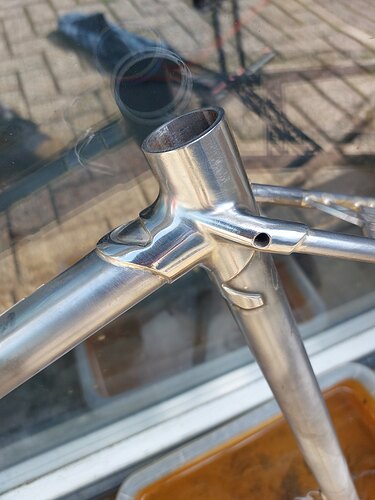
But a first quick test worked pretty nicely. Frame is off to powdercoat and then I’ll probaby spend a day carefully finishing the shit out of the lugs.
I had Darryll at Llewellyn Cycles here in Australia show his method. He is teh best in teh world at getting his lugs perfectly polished, in my opinion. The reflection is perfect in every one of them but the hours he puts in to get them that way is ludicrous. I swore off ever offering or agreeing to do them ever. He does them about 6 or 7 times with the higher grades of sandpaper then uses a soft buffing wheel.
There’s some fairly common (at least in AM) bulk finishing techniques people use for different AM metals. Company called REM (https://www.remchem.com) has a chemical/mechanical finishing technique, ISO Finishing (What Is Isotropic Finishing and Other FAQs | ISO Finishing Inc.) knows tumbling really well and can get some great results. Then there is Chemical Milling which uses some nasty stuff to get the roughness off. Should be able to look up companies around where you are for chem milling. All of these though will likely be fairly expensive for one-offs/low volumes though…
In our shop, I use a combo of shot blasting, then wire wheel, then buffing wheel to get some pretty good results. Shot blasting with an abrasive, like alumina or carbide, seems to work best to set a good even base for the wheel work.
Shot blasting is a good tip, I’ll try that with the dropouts for the next build. ![]()
I assume back purging is necessary for welding 4130 to something like 316L, can anyone speak to this? I’ve used Solar Flux in the past for welding stainless alloys, but the extra insurance of argon seems warranted for printed parts.
I’m curious what the transition thickness for back purging being necessary is. It seems feasible to add a thick lip around a weld joint on a printed part. At that point, it’s probably simpler to set up a back purge setup though…
Thanks for this callout. That webpage has a great white paper (non peer reviewed):
It has some bias (because they are selling the service) and not enough samples IMO, but it still has some great insight. The TLDR is that the smoothed surfaces can double the fatigue life:
Totally worth a read if you are poking around in 3D-printed parts. Here it is in PDF form to preserve the research:
Surface Treatment of Powder-Bed Fusion Additive Manufactured Metals for Improved Fatigue Life - REM Surface Engineering.pdf (1.6 MB)
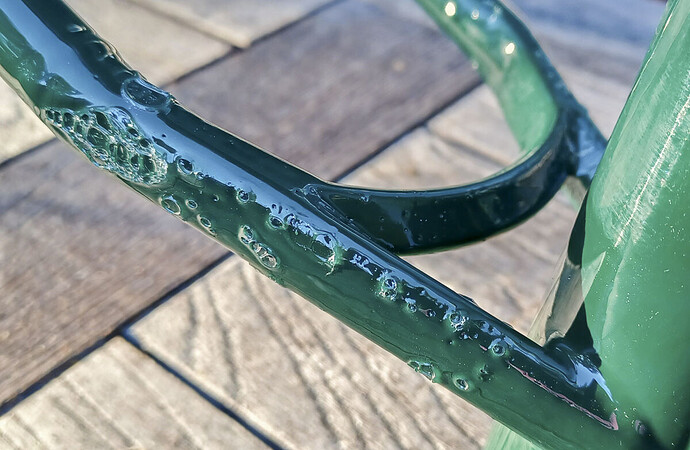
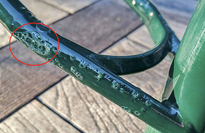
Looks like the walls of PVD’s latest batch of prints let pressurized air escape while the powder coat on his new frame was curing. Any idea what caused this @Daniel_Y @DrSkidz? Every print is going to have some (hopefully low) level of porosity, but unless these look like foam under a microscope I’m having a hard time seeing how the pores could connect and let air through. Maybe lack of fusion between build layers?
https://www.peterverdone.com/permeable-prints/
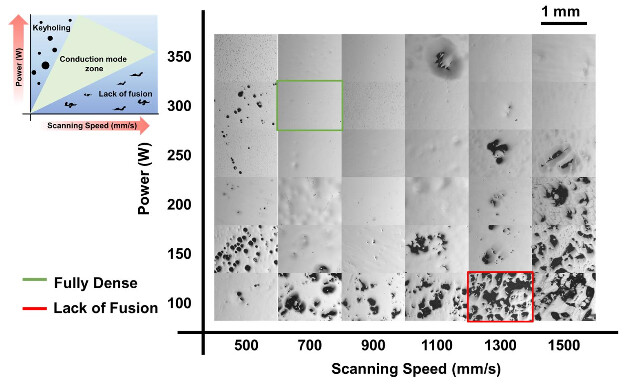
Here’s an interesting figure showing how internal porosity can be affected by machine settings like laser power and scanning speed (Ref). @DrSkidz have you ever seen a fab try to use lower power, higher speed scanning strategies to save on energy cost and build time? Or are these settings pretty much locked down in a safe range by the machine OEMs?
Wow that’s incredible, sounds like venting solved it from his post which is comforting. I’m surprised the parts weren’t vented already for back purge. Makes me more concerned I’m not properly cleaning parts in case there are trapped oils or contaminants in the “pores” of the material.
Adam Prosise mentioned baking the parts in a 400 deg F oven for 20 - 30 mins to remove the chance of this sort of thing happening. I think it might be just the porosity might be localised and that it is all interconnected through the volume. So only the pores close to the surface would have any affect on paint and not being a purging issue.
This looks like another case of him getting bunk parts from cheap or inexperienced parts suppliers. @photon, you can definitely change processing parameters to achieve different results but it is usually done in very specific applications. For injection mold tooling (really thick parts) the only critical areas are the outer walls so it is fairly common to print at a faster build rate with lower density (~10%) in the inside bulk then have the outer 3-5 mm at full density for surface finishing. The level of defects assumed to cause that type of failure in his powder coat would be from a serious build problem with a lot of lack of fusion porosity. In the past, a lot more was locked down but as the industry becomes more familiar with the technology things have opened up to be adjustable.
@DrSkidz Awesome, thanks for the response. Really curious what vendor he is using, based on the number of parts he’s ordered over the last year or two I’m guessing it is one of the cheaper options out there.
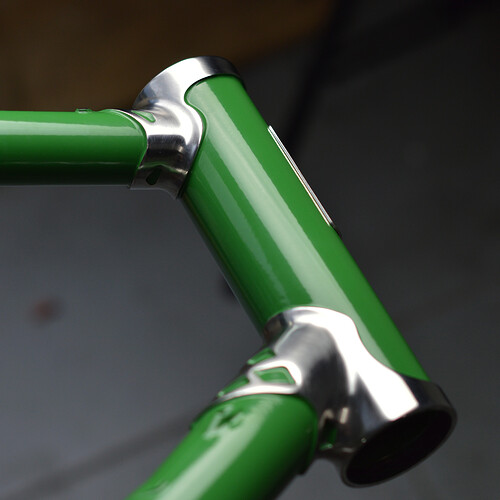
Finished the printed lug frame yesterday and while the polish is not as good as it could be but I have learned a lot about finishing 3D printed parts like this, and both love and hate it. But still I am pretty stoked for the result and can’t wait to use this on other bikes!
Concerning the bubbly PVD bits: I had a similar issue with the rear of my fully, but luckily nowhere as bad as his bike. But also a completely closed part without ventholes. My parts are the € 0.6/gram option from 3DPBS and I know PVD didn’t get these parts from him.
We drilled a venthole in the yoke and I hope to see next week if this has solved this issue.
I did a bit of investigation and asked our print supplier. I didn’t want to ask where people’s parts are printed, but I have a feeling most go through the supplier NMW uses.
I don’t think the parts are that porous
I find it unlikely that gas was escaping through the parts. I think the level of porosity for that to happen would be obvious.
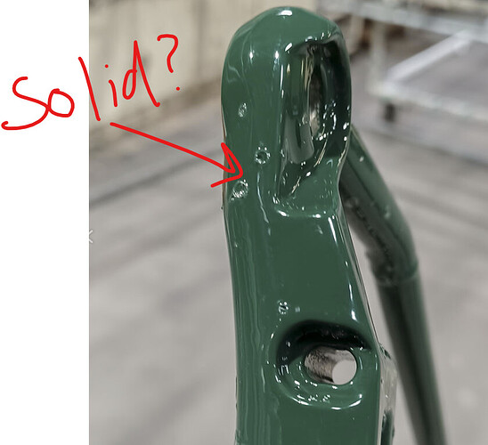
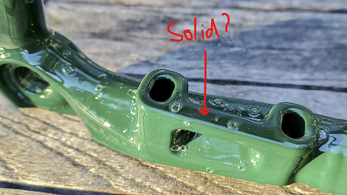
Also, the bubbles are forming in places that are solid:
Surface contamination?
I think the most likely explanation is surface contamination. It is claimed that the bubbles went away after venting, but I think it is more likely the bubbles went away after the frame was stripped (I assume chemically).
Our supplier recently had an issue where oil was getting onto the parts somewhere along the process. The contamination was obvious, and they sent us new parts without asking. Because of the surface texture contaminated parts are very hard to clean. I think bead blasting the contamination just embeds it further in the surface.
Surface Porosity?
We get a tiny bubble just like @project12 once in a while:
Printed parts are never going to be 100% solid. My theory for the random bubbles is either a tiny cavity on the surface “opens up” during heating, or the powder struggles to attach to the texture of the part.
Conclusions:
As always, I encourage people to do their own investigation and research. Just because someone printed something does not mean it’s a good idea!
The strength of a part comes from its design. it’s easy to get carried away with the ability to print complex shapes and chase weight and cost savings, but printability (the ease of printing) should be the biggest concern when designing additive parts. Just because you can does not mean you should!
A perfect example is printing zip tie guides directly onto parts:
- stress riser
- sudden change in wall thickness
- two supported overhangs.
An innocuous feature has three of the no-nos of additive. It may look perfectly fine (and it might be), but to me, it carries too much risk. Since you are brazing zip tie guides to a frame anyway, it’s not much more time to braze it onto the printed part.
Another clarification: just because a print partner is low cost, does not mean it is bad. Our print partner in Asia is much cheaper than domestic options, but they have been the most open to feedback, open to improving their process, and easy to communicate with. I have had the exact opposite experience with domestic print partners who have a know-it-all attitude.
I wonder if what we’re seeing is an artifact of surface roughness more than anything else? I wouldn’t be surprised if most powder coaters just sand blast, wipe, and shoot. For smooth parts like tubes and CNC’d dropouts this is totally adequate, but you wouldn’t get any grease/oil/etc out of an already-rough part that way.
I always pre-bake parts for 30min at 400ºF before coating to ensure proper offgassing. Seems like this could be an important step for additive parts?
My coater (from the 3d part) also pre-bakes every frame at 240C for 30 minutes, so that’s probably not the issues here.
Nice thing about polishing these printed parts is that you see more clearly the consistency. With the printed lugs I had one tiny pinhole that seemed deeper than I wanted to sand, and several superficial pits that went away with some light sanding. Neither of these things showed up clearly when the were their deliverd sanded finish.
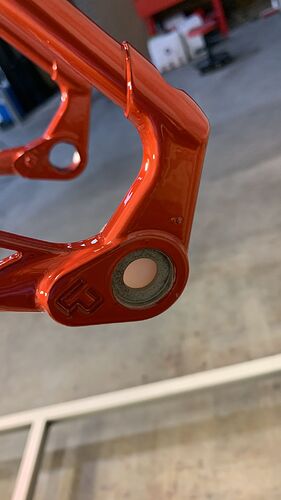
Without getting these parts parts in a micro-CT machine or sectioning, polishing, and examining problem areas under a good microscope all we can do is speculate. I really hope the bubbles are due to surface contamination. The area I circled below is what gave me the most concern - a lot of gas would have to be generated in one spot to create that many large bubbles.
We’re lucky PVD shares so much of his work and has a relatively large community of followers. Here’s some more information I’ve been able to dig up from his social feeds:
-
This frame did apparently undergo a pre-bake prior to powder coating, though I’m unsure of the exact cycle.
-
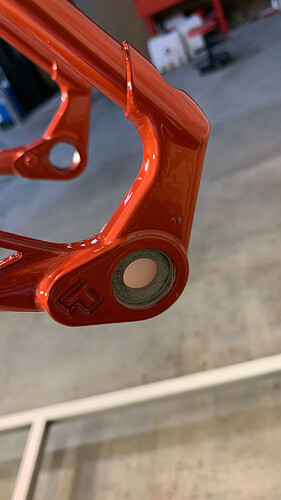
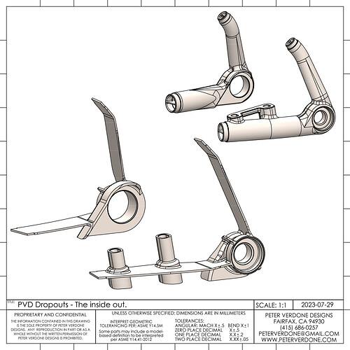
PVD is pretty comprehensive when he shells these parts, so it is possible the problem areas on that dropout were pressurized. Here’s a picture of the internal structure of what I think are the same dropouts.
-
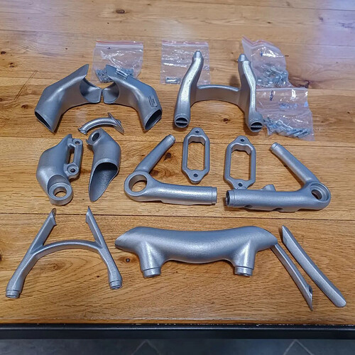
I have no idea how obvious surface contamination would be, but the raw parts look clean in this photograph, at least.
-
Max Roe, another builder working with printed metal, mentioned having a similar issue on some of his parts where support material was removed. (Side note: Max does really incredible work and not many people seem to know about him - highly recommend checking out his Instagram.)
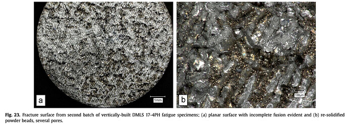
And, finally, here’s a photo of the fracture surface of a 17-4 DMLS fatigue specimen that was not completely fused during printing. If the same happened to a thin-wall bicycle part it definitely seems possible that air could make it through the walls.
Another batch of 17-4 fatigue specimens tested for this paper did not have the same issue. Directly quoting the authors:
Since no differences were observed on the exterior surfaces of these two batches of ostensibly identical materials, an important concern arises: How will end-users and providers of DMLS fabrication services develop assurance that components created with this AM process possess optimal material properties? This issue appears to be of greatest significance for products that will be exposed to dynamic mechanical loads, since fatigue failures are most often not accompanied by gradual signs of declining health.
Bad prints happen, and aren’t necessarily an indictment of any particular supplier, but it is important to have a way to catch them. Every build plate I’ve seen with bike parts on it from Ram3D also has tensile dogbone specimens printed, and this is presumably to catch potentially catastrophic build issues before they make it to a customer.
Adding a couple more comments that I don’t want to get lost in the speculation about porosity:
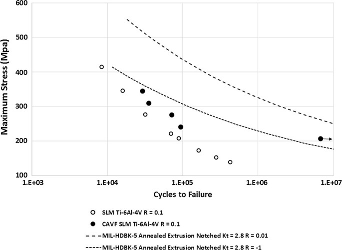
This is super important to keep in mind, material selection/quality is only part of the picture. Fatigue data I’ve seen for the common materials builders are using (Ti64, SS 316L, 17-4, 15-5) indicates that doubling the stress (or less) can easily knock hundreds of thousands of cycles of life off of a test specimen in the range I’m guessing most bike frames have to pass (100,000 to 1,000,000 cycles). No idea if this applies directly to bike loads/part geometry, but it helps contextualize all the talk about stress concentrations. With as much design freedom as there is in AM, it is really easy to inadvertently cross the line (I have no idea where the line is).
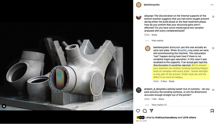
Good material and process control takes a lot of effort and is extremely hard to do well, at least where my background is (not AM). Screening tests are only part of the picture, and tensile specimens probably have limited utility for parts with a fatigue failure mode - they’re probably most effective at screening Ti, and even then may only be effective once porosity is in the single digit percents. Bastion does all their own printing and apparently evaluates rotating beam fatigue specimens from each build plate:
Does anyone here have experience with printing AlSi10Mg? I’m working on a partial-lugged-carbon frame and the seat mast/seat stay/top tube cluster would be a good candidate for that material.
![]() yes! There’s some other aluminums out there too that are close to the 6061/7075 range but would be more expensive. Haven’t seen anyone use aluminum for bikes yet though.
yes! There’s some other aluminums out there too that are close to the 6061/7075 range but would be more expensive. Haven’t seen anyone use aluminum for bikes yet though.
Great write-ups @photon! Kind of tied into all of this is that you also can’t be certain your part is OK if the tensile or fatigue bar is. It’s all local to the part. The tensile or fatigue bars (what we call witness coupons) are good indicators that the overall machine/process (including heat treat) was operating normally.
In aerospace, it’s pretty common to also have in-process monitoring tools that can look at the meltpools of every part and give you indications whether or not it is ok. This is still in its teenage years but maturing fast. At EOS, we have Melt Pool Monitoring (for academia) and Optical Tomography. The algorithms determining whether or not the signal resulted in a defect are getting better every day but we still aren’t there. In 5 years I would see this being standard on most high end industrial systems.
